Table of Contents
Advertisement
Quick Links
Advertisement
Table of Contents
Troubleshooting

Related Manuals for AAON ASM02655


Summary of Contents for AAON ASM02655
- Page 1 Main DX Barrel Chiller Controller Technical Guide...
- Page 2 AAON Controls Support: 866-918-1100 Java™ is a registered trademark of Oracle, Inc. It is the intent of AAON to provide accurate and current AAON assumes no responsibility for errors or omissions in product information. However, in the interest of product this document.
-
Page 3: Table Of Contents
TABLE OF CONTENTS OVERVIEW ........................9 General Information ..............................9 WIRING .......................... 10 Important Wiring Considerations ........................... 10 Main DX Barrel Chiller Controller and Refrigerant Module I/O Maps ..............11 Vestibule Module and Chiller Pumping Module I/O Maps ..................12 Evaporative Condenser Module I/O Maps ......................13 Main DX Barrel Chiller Controller Input Wiring ...................... - Page 4 TABLE OF CONTENTS LCD SCREENS ....................... 49 LCD Display, Navigation Keys and Editing Keys ....................49 LCD SCREENS ....................... 50 Main Screens Map ..............................50 Settings Screens ..............................51 Glycol Screens ..............................52 Status Screens ..............................53 Alarms ................................... 54 RSM - LCD SCREENS ....................
- Page 5 TABLE OF CONTENTS TOUCHSCREEN INTERFACE ..................94 Overview ................................94 Start and Logging In Screens ..........................95 Changing the Passcode ............................96 Button and Icon Function ............................97 System Settings ..............................98 Details Screens ..............................99 Schedules and Overrides ............................ 100 Setting, Saving and Restoring Holidays and Schedules ..................
- Page 6 FIGURES FIGURES Main DX Barrel Chiller Controller Input Wiring Figure 1: ....................14 Main DX Barrel Chiller Controller Output Wiring Figure 2: ....................15 Chiller Refrigerant Module Input Wiring Figure 3: .......................16 Chiller Refrigerant Module Output Wiring Figure 4: ......................17 Chiller Pumping Module Input Wiring Figure 5: ........................18 Chiller Pumping Module Output Wiring...
- Page 7 FIGURES Keypad Data Entry Screen Figure 45: ...........................104 Alarms Logs Screen - Administrative Access Figure 46: ....................105 Chiller Rocker Switch Panel (Three Circuit Switches Shown) Figure 47: ...............106 Prism 2 - DX Chiller Main Controller Status Screen Figure 48: ..................108 Prism 2 - Controller Setpoint Screens Figure 49: ........................109...
- Page 8 TABLES TABLES Main DX Barrel Chiller Controller, Chiller Refrigerant Module and Chiller Pumping Module Table 1: Electrical and Environmental Requirements .......................10 Evaporative Condenser Module and Vestibule Module Electrical and Environmental Requirements Table 2: ..10 Main DX Barrel Chiller Controller Inputs and Outputs Table 3: ..................
-
Page 9: Overview
OVERVIEW General Information Control System Features and Applications The Main DX Barrel Chiller Controller provides control of the chilled water for a DX Barrel Chiller. The Main DX Barrel Chiller Controller has an on-board BACnet port for connection to a BACnet MS/TP BAS network. There are also two E-BUS expansion ports which allow for the connection of the Chiller Refrigerant Module, Chiller Pumping Module, Evaporative Condenser Module, and Vestibule Module via... -
Page 10: Wiring
The Main DX Barrel Chiller Controller and modules are installed and wired at the AAON factory. Some of the following information may not apply to this... -
Page 11: Main Dx Barrel Chiller Controller And Refrigerant Module I/O Maps
WIRING Main DX Barrel Chiller Controller and Refrigerant Module I/O Maps Input/Output Maps CHILLER REFRIGERANT MODULE Analog Inputs See Table 3, this page, for the Main DX Barrel Chiller Controller Inputs/Outputs and Table 4, this page, for the Chiller Refrigerant Suction Line Pressure (0-5VDC) (AI1) Module Inputs/Outputs. -
Page 12: Vestibule Module And Chiller Pumping Module I/O Maps
WIRING Vestibule Module and Chiller Pumping Module I/O Maps VESTIBULE MODULE CHILLER PUMPING MODULE Analog Inputs Analog Inputs - 10K @ 77ºF Type III Thermistors Not Used (AI1) Waterside Economizer Primary Mixing Valve Outlet Temperature Sensor (AI1) (Valve Outlet Mixed Not Used (AI2) Temperature) Not Used (AI3) -
Page 13: Evaporative Condenser Module I/O Maps
WIRING Evaporative Condenser Module I/O Maps EVAPORATIVE CONDENSER MODULE Analog Inputs Condenser Pump 1 Amps (SP) Condenser Pump 2 Amps (HP) Sump Temperature Sensor 1 (TEMP1) Sump Temperature Sensor 2 (TEMP2) Sump Temperature Sensor 3 (TEMP3) Low Sump (Dry Contact) (TEMP4) Binary Inputs Pump 1 Pressure Switch (BI1) Pump 2 Pressure Switch (BI2) -
Page 14: Main Dx Barrel Chiller Controller Input Wiring
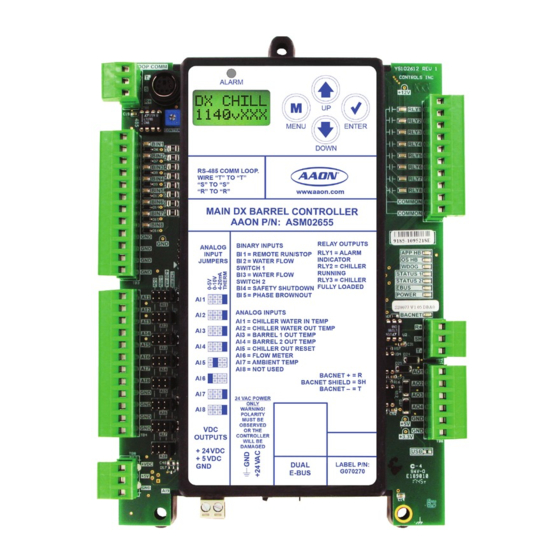
Temperature Sensor DOWN Mount in chiller entering RS-485 COMM LOOP. WIRE “T” TO “T” water line “S” TO “S” “R” TO “R” www.aaon.com Chiller Water Out Temperature Sensor Mount in chiller leaving RELAY OUTPUTS BINARY INPUTS ANALOG water line RLY1 = ALARM... -
Page 15: Main Dx Barrel Chiller Controller Output Wiring
NOTE: RS-485 COMM LOOP. WIRE “T” TO “T” All relay outputs are normally open “S” TO “S” “R” TO “R” www.aaon.com and rated for 24 VAC power only. 1 amp maximum load. RELAY OUTPUTS BINARY INPUTS ANALOG RLY1 = ALARM... -
Page 16: Chiller Refrigerant Module Input Wiring
Compressor 1 Status Compressor 2 Status Compressor 1 VFD Fault ALARM Circuit Disable MENU ENTER Condenser Fan Fault DOWN www .aaon.com Suction Line Pressure Transducer BINARY INPUTS RELAY OUTPUTS ANALOG RLY1 = COMP 1 BIN1 = COMP 1 STAT Discharge Line... -
Page 17: Chiller Refrigerant Module Output Wiring
COMPRESSOR 2 ENABLE CONDENSER FAN MENU ENTER 24 VAC POWER DOWN NOTE: www .aaon.com All relay outputs are normally open and rated for 24 VAC power only. 1 amp maximum load. BINARY INPUTS RELAY OUTPUTS ANALOG BIN1 = COMP 1 STAT... -
Page 18: Chiller Pumping Module Input Wiring
DOWN Outlet Temp Sensor BIN4 RLY6 BIN5 RLY7 Mount in WSE mixing BIN6 RLY8 valve outlet water line BIN7 www .aaon.com COMMON BIN8 COMMON BIN9 Heat Exchanger Waterside BIN10 SOFTWARE Outlet Temp Sensor RELAY OUTPUTS BINARY INPUTS R1 = WSE FAN... -
Page 19: Chiller Pumping Module Output Wiring
PRIMARY A PUMP 2 ENABLE DOWN SEC PUMP 1 SEC PUMP 2 PRIMARY B PUMP 1 ENABLE PRIMARY B PUMP 2 ENABLE www .aaon.com R 24 VAC POWER 24 VAC POWER BINARY INPUTS RELAY OUTPUTS B 1 = WSE VFD FAULT... -
Page 20: Evaporative Condenser Module Input Wiring
Sump Temp 2 DOWN Sump Temp 3 EVAPORATIVE CONDENSER MODULE AAON P/N: ASM02318 www.aaon.com Low Sump SP = COND PUMP 1 AMPS RLY1 = CONDENSER PUMP 1 RUN RLY2 = CONDENSER PUMP 2 RUN HP = COND PUMP 2 AMPS... -
Page 21: Evaporative Condenser Module Output Wiring
All relay outputs are normally open and rated for 24 VAC power only. EVAPORATIVE CONDENSER MODULE 1 amp maximum load. AAON P/N: ASM02318 www.aaon.com SP = COND PUMP 1 AMPS RLY1 = CONDENSER PUMP 1 RUN RLY2 = CONDENSER PUMP 2 RUN... -
Page 22: Vestibule Module Input Wiring
Vestibule Modules can be connected, depending on the 23, for output wiring. size of the system. ALARM MENU ENTER DOWN VESTIBULE MODULE www.aaon.com AAON P/N: ASM02650 +5 V SP-1 NOT USED RELAY CONTACT RELAY OUTPUT RATING IS 1 AMP TERMINALS +5 V... -
Page 23: Vestibule Module Output Wiring
All relay outputs are normally open DOWN and rated for 24 VAC power only. 1 amp maximum load. VESTIBULE MODULE www.aaon.com +5 V AAON P/N: ASM02650 SP-1 NOT USED RELAY CONTACT RELAY OUTPUT RATING IS 1 AMP +5 V TERMINALS... -
Page 24: Sequence Of Operations
SEQUENCE OF OPERATIONS Main DX Barrel Chiller Controller - Overview DX Barrel Chiller Operation Internal Schedule The chiller controls have an internal schedule which may be used The Main DX Barrel Chiller Controller directly operates the to automate chiller operations on a timed basis. This schedule following components to provide chilled water: defaults to always on and, in combination with the Remote Unit •... -
Page 25: Main Dx Barrel Chiller Controller - Off And Run Modes
SEQUENCE OF OPERATIONS Main DX Barrel Chiller Controller - Off and Run Modes Off Mode Waterside Economizer Operation (runs on the Chiller Pumping Module) If the Remote Enable/Disable is disabled, the internal schedule (if If Waterside Economizer is present and the ambient temperature used) has transitioned to the Unoccupied Mode, or if an override is below the entering water temperature by the adjustable is indicating stop, the chiller will enter the Off Mode. -
Page 26: Main Dx Barrel Chiller Controller - Mechanical Chiller Overview
SEQUENCE OF OPERATIONS Main DX Barrel Chiller Controller - Mechanical Chiller Overview Mechanical Chilling Overview Dual Barrels with Single Primary Water Circuit The compressor and circuit operation will stage each barrel The Main DX Barrel Chiller Controller, in combination with one independently as its own barrel. -
Page 27: Main Dx Barrel Chiller Controller - Safety Checks
SEQUENCE OF OPERATIONS Main DX Barrel Chiller Controller - Safety Checks Safety Checks Freeze Protection If the barrel out temperature drops below the barrel out freeze Safeties represent operating conditions which may override or protection limit, a freeze protection failure alarm will be otherwise affect normal operation. -
Page 28: Chiller Refrigeration Module Operation
SEQUENCE OF OPERATIONS Chiller Refrigeration Module - Operation Chiller Refrigeration Module Operation Condenser Operation The refrigeration module controls the following components to The condenser has two modes of operation: maintain a target Barrel Out Water Temperature: • Condenser Off • One compressor or two compressors in tandem •... -
Page 29: Chiller Refrigeration Module - Safety Checks
SEQUENCE OF OPERATIONS Chiller Refrigeration Module - Safety Checks Safety Checks Emergency Shutdown In Emergency Shutdown, a pump-down operation will not be performed on the circuit. All compressors will be deactivated and the electronic expansion valve will close. Alarms Alarms generally provide notification of an abnormal condition in the circuit and may cause an override or alter certain operations. -
Page 30: Vestibule Module - Operation And Safeties
SEQUENCE OF OPERATIONS Vestibule Module - Operation and Safeties Vestibule Module Operation Vestibule Safeties Refrigerant Leak Detection Vestibule Module operation includes the following: • Heating If the module detects a refrigerant leak, the heat output, coil pump, and coil fan output will deactivate. The vent fan output will •... -
Page 31: Chiller Pumping Module - Waterside Economizer Operation
SEQUENCE OF OPERATIONS Chiller Pumping Module - Waterside Economizer Operation Chiller Pumping Module Operation Fan Stage As the second stage of chilling, the fan will be activated and The chiller pumping module operates the following three optional modulate to regulate the output water temperature. There is a components: hysteresis in the fan start/stop operation to avoid fan cycling. -
Page 32: Chiller Pumping Module - Plate Heat Exchanger Operation
SEQUENCE OF OPERATIONS Chiller Pumping Module - Plate Heat Exchanger Operation Plate Heat Exchanger Operation Primary Loop Isolation Freeze Protection While the chiller is in Off Mode, if any of the three exchanger The plate heat exchanger has no direct operation, it is a passive temperature sensors drop below 35°F, the following events will device. -
Page 33: Chiller Pumping Module - Water Circuit Pumping Operation
SEQUENCE OF OPERATIONS Chiller Pumping Module - Water Circuit Pumping Operation Water Circuit Pumping Operation Lead/Lag Operation and Backup Pump If Lead/Lag Operation is configured, a Lead/Lag calculation The water circuit pumping operation provides all pump is performed every seven days at which point the module will operations for chilled water in the chiller and optionally in the switch to the pump with the least amount of run time. -
Page 34: Trend Logs
SEQUENCE OF OPERATIONS Trend Logs DX Barrel Chiller Trend Logs There are instances in the trend logs where a “#” is used in place of a value. These are references to the different barrels, circuits, and compressors that may be present on the system. For example, B1C1Flt would indicate a fault on Barrel 1, Circuit 1. -
Page 35: Trend Log Alarm Bit Strings
SEQUENCE OF OPERATIONS Trend Log Alarm Bit Strings ALARM GROUP 1 ALARM GROUP 5 Bit Value Description Bit Value Description Sensor Failure Module Alarms Entering Water Sensor RSM Module B1:C1 Leaving Water Sensor RSM Module B2:C1 Barrel #1 Out Sensor RSM Module B1:C2 Barrel #2 Out Sensor RSM Module B2:C2... -
Page 36: Table 15: Evaporative Condenser Alarms Bit String
SEQUENCE OF OPERATIONS Trend Log Alarm Bit Strings Trend Log Bit String Decoding EVAPORATIVE CONDENSER ALARMS Bit Value Description Bit string values allow the manipulation of binary data in useful Sump Heater Status (1: Cannot Run) ways. For instance, a single trend log item may need to represent multiple simultaneous true conditions. -
Page 37: Troubleshooting
TROUBLESHOOTING Alarms and Faults Alarms and Faults Waterside Economizer VFD Fault If the VFD is indicating a fault, an alarm will generate and operations will continue as if the VFD were operational. Waterside Economizer Primary Outlet (Leaving Water) Temperature Sensor Failure If the Waterside Economizer Primary Outlet (Leaving Water) Temperature Sensor fails, an alarm will indicate the sensor failure. -
Page 38: Main Dx Barrel Chiller Controller Led Diagnostics
TROUBLESHOOTING Main DX Barrel Chiller Controller LED Diagnostics Main DX Barrel Chiller Controller LEDs Communication LEDs This yellow LED will blink to signal E-BUS EBUS: The Main DX Barrel Chiller Controller is equipped with LEDs communications. that can be used to verify operation and perform troubleshooting. There are LEDs for communication, operation modes, and This yellow LED will light up and blink continuously BACNET:... -
Page 39: Main Dx Barrel Chiller Controller Led Locations
LEDs MENU ENTER DOWN RS-485 COMM LOOP. BINARY WIRE “T” TO “T” INPUT “S” TO “S” “R” TO “R” www.aaon.com LEDs OPERATING SYSTEM HB RELAY OUTPUTS BINARY INPUTS ANALOG RLY1 = ALARM INPUT B 1 I = REMOTE RUN/STOP STATUS 1... -
Page 40: Refrigerant Module Led Diagnostics
TROUBLESHOOTING Refrigerant Module LED Diagnostics Refrigerant Module LEDs Refrigerant Module Binary Input LEDs This green LED indicates Compressor 1 Status and will BI1: The Chiller Refrigerant Module is equipped with LEDs that can light up when Compressor 1 is running. be used to verify operation and perform troubleshooting. -
Page 41: Refrigerant Module Led Locations
Refrigerant Module LED Locations ALARM ALARM MENU ENTER RELAY LEDs DOWN BINARY INPUT LEDs www .aaon.com POWER LED BINARY INPUTS RELAY OUTPUTS ANALOG RLY1 = COMP 1 BIN1 = COMP 1 STAT INPUT RLY2 = COMP 2 BIN2 = COMP 2 STAT... -
Page 42: Chiller Pumping Module Led Diagnostics
TROUBLESHOOTING Chiller Pumping Module LED Diagnostics Chiller Pumping Module LEDs Communication LED This yellow LED will blink to signal E-BUS EBUS: The Chiller Pumping Module is equipped with LEDs that can be communications. used to verify operation and perform troubleshooting. See Figure 13, page 43. -
Page 43: Chiller Pumping Module Led Locations
ALARM LED ALARM MENU ENTER RELAY LEDs DOWN BINARY INPUT POWER LED LEDs www .aaon.com OPERATING SYSTEM HB BINARY INPUTS RELAY OUTPUTS B 1 = WSE VFD FAULT R1 = WSE FAN ANALOG R2 = GLYCOL PUMP BI2 = NOT USED... -
Page 44: Evaporative Condenser Module Led Diagnostics And Locations
POWER LEDs MENU ENTER DOWN EVAPORATIVE CONDENSER MODULE AAON P/N: ASM02318 www.aaon.com SP = COND PUMP 1 AMPS RLY1 = CONDENSER PUMP 1 RUN RLY2 = CONDENSER PUMP 2 RUN HP = COND PUMP 2 AMPS RLY3 = SUMP HEATER ENABLE... -
Page 45: Vestibule Module Led Diagnostics
RELAY LEDs ALARM COMM POWER LEDs MENU ENTER DOWN www.aaon.com VESTIBULE MODULE +5 V AAON P/N: ASM02650 SP-1 NOT USED RELAY OUTPUT RELAY CONTACT RATING IS 1 AMP TERMINALS +5 V NOT USED MAX @ 24 VAC HP-1 VENT FAN... -
Page 46: Thermistor Sensor Testing
TROUBLESHOOTING Thermistor Sensor Testing Temperature/Resistance for Thermistor Sensor Testing Instructions Thermistor Sensors Use the resistance column to check the thermistor sensor while disconnected from the controllers (not powered). The following sensor voltage and resistance table is provided to Use the voltage column to check sensors while connected to aid in checking sensors that appear to be operating incorrectly. -
Page 47: Suction Pressure Transducer Testing
TROUBLESHOOTING Suction Pressure Transducer Testing 0 - 250 PSI Suction Pressure Transducer Place the positive lead from the meter on the +5V terminal located on the module(s) terminal block. Place the negative lead Testing for R410-A Refrigerant from the meter on the ground (GND) terminal located adjacent to the +5V terminal on the module(s) terminal block. -
Page 48: Discharge Pressure Transducer Testing
TROUBLESHOOTING Discharge Pressure Transducer Testing Discharge Pressure Sensor Testing Discharge Pressure Transducer 0-667 PSI Pressure – Voltage Chart for R410-A Refrigerant 0-667 PSI The Discharge Pressure is obtained by using the Discharge Pressure Signal Pressure Signal Pressure Sensor, which is connected into the discharge line of DC Volts DC Volts the compressor. -
Page 49: Lcd Screens
DX BARREL MAIN CONTROLLER - LCD SCREENS LCD Display, Navigation Keys and Editing Keys LCD Display Screen and Navigation Keys Navigation Key Function The LCD display screens and buttons show status and alarms, and enable force modes. See Figure 16, this page, and refer to MENU Use the MENU key to move through screens within Main Menu categories and return to the... -
Page 50: Lcd Screens
DX BARREL MAIN CONTROLLER - LCD SCREENS Main Screens Map Main DX Barrel Chiller Controller Main Screens Map Refer to the following map when navigating through the Main DX Barrel Chiller Controller Screens. The first screen is an initialization screen. To scroll through the rest of the screens, press the button. -
Page 51: Settings Screens
DX BARREL MAIN CONTROLLER - LCD SCREENS Settings Screens Settings Screens DEVICEID 15000 Refer to the following map when navigating through the Settings Screens. From the Settings Screen, press to scroll <ENTER> through the screens. BACnet CURRENT DEVICE ID A Device ID of up to seven digits can be entered. The <ENTER>... -
Page 52: Glycol Screens
GLYCOL AT % Use this screen to see the current glycol level. Any changes made to Chiller. this screen are not saved until validated by a HashCode From AAON Controls Engineering. Key Code XXXXXX KEY CODE Submit this code to AAON Controls Engineering. -
Page 53: Status Screens
DX BARREL MAIN CONTROLLER - LCD SCREENS Status Screens Status Screens OA Temp 78.5 ° Refer to the following map when navigating through the Status Screens. From the Status Screen, press to scroll <ENTER> through the screens. OUTDOOR AIR TEMPERATURE Status Barrel 1 °... -
Page 54: Alarms
DX BARREL MAIN CONTROLLER - LCD SCREENS Alarms Alarm Screens Alarm Description Inlet SENSOR: The Chiller Water Inlet Temperature If there are no Alarms, the Alarm Screen will display “No Sensor has failed. Alarms.” If there are alarms present, the screen will display, Outlet SENSOR: The Chiller Water Outlet Temperature “Alarms.”... -
Page 55: Rsm - Lcd Screens
RSM - LCD SCREENS Main Screens Map Main Screens Map ALARM FAULTS Refer to the following map when navigating through the Refrigerant Module Main Screens. To scroll through the screens, press the button. <MENU> Press to scroll through ALARM FAULTS screens. Press to go to the ALARM LOCKOUTS screen. -
Page 56: Rsm Screens
RSM - LCD SCREENS RSM Screens Refrigerant Module Screens BARREL Refer to the following map when navigating through the Refrigerant Module Screens. Press to scroll through <ENTER> the screens. NUMBER OF BARRELS (1-2) 1149vXXX CIRCUIT NUMBER OF CIRCUITS (1-2) EBUS COM #### E-BUS COMMUNICATION DIAGNOSTICS This screen shows the number of COMM packets received. -
Page 57: Status Menu Screens
RSM - LCD SCREENS Status Menu Screens Status Menu Screens C1MINRUN Refer to the following map when navigating through the Status Screens. From the STATUS MENU Screen, press <ENTER> scroll through the screens. COMPRESSOR 1 MINIMUM RUN TIME (in seconds) STATUS MENU C1MINOFF... -
Page 58: Sensor Menu Screens
RSM - LCD SCREENS Sensor Menu Screens Sensor Menu Screens EVAPTEMP XX.X ° F Refer to the following map when navigating through the Sensor Screens. From the SENSOR MENU Screen, press <ENTER> EVAPORATION TEMPERATURE READING FROM INPUT scroll through the screens. SENSOR MENU DISCTEMP... -
Page 59: Setpoint Status Screens
RSM - LCD SCREENS Setpoint Status Screens Setpoint Status Screens Refer to the following map when navigating through the Screens. From the SETPOINT STATUS Screen, press to scroll <ENTER> through the screens. SETPOINT STATUS LVGH2OSP ° XX.X LEAVING WATER TEMPERATURE SETPOINT SHEAT SP XX.X °... -
Page 60: Alarm Screens
RSM - LCD SCREENS Alarm Screens Alarm Warning Screens FAULTS! If an alarm is present, the ALARM LED above the LCD display will light up red and blink. The Alarms will display and scroll automatically from the ALARMS screen when alarms are present. FAULTS! This will be displayed if there are active faults. -
Page 61: Table 26: Rsm Lockouts
RSM - LCD SCREENS Alarm Screens LOCKOUT! LOCKOUT! This will be displayed if there are active lockouts. LOCKOUTS NO LOCKOUTS This will be shown if there are no current lockouts. Lockout Description SUCT PSI LOCKOUT: Suction Pressure System Lockout LOW DISC LOCKOUT: Low Discharge Pressure Lockout C1 >AMPS LOCKOUT: Compressor 1 Over Current Lockout... -
Page 62: Chiller Pumping Module - Lcd Screens
CHILLER PUMPING MODULE - LCD SCREENS Main Screens Map Main Screens Map SETPOINT STATUS Refer to the following map when navigating through the Chiller Pumping Module Main Screens. To scroll through the screens, press the button. <MENU> Press to scroll through the SETPOINT STATUS screens. 1130v### Press to go to the PUMP RUNTIME screen. -
Page 63: Module Screens
CHILLER PUMPING MODULE - LCD SCREENS Module Screens Module Screens ISOLATED Refer to the following map when navigating through the Chiller Pumping Module Screens. From the Waterside Economizer Main Screen, press to scroll through the screens. <ENTER> ISOLATED GLYCOL LOOP NO, WSE, or PRIM/SEC It will display WSE if the economizer is isolated. -
Page 64: Module Screens
CHILLER PUMPING MODULE - LCD SCREENS Module Screens SECONDRY FRZ PROT SINGLE Enabled FREEZE PROTECTION STATUS SECONDARY PUMP CONFIGURATION This screen will be present only if both the Waterside Economizer This screen will be present only if the Chiller Pump is enabled and and Chiller Pump are enabled. -
Page 65: System Status Screens
CHILLER PUMPING MODULE - LCD SCREENS System Status Screens System Status Screens FAN VFD X.X% Refer to the following map when navigating through the System Status Screens. From the SYSTEM STATUS screen, press to scroll through the screens. <ENTER> CURRENT FAN VFD DRIVE LEVEL This screen will only be present if Waterside Economizer is enabled. - Page 66 CHILLER PUMPING MODULE - LCD SCREENS System Status Screens BLDG PMP VFD XXX% BUILDING PUMP VFD CURRENT DRIVE STATUS This screen will be present only if the Chiller Pump is enabled and configured as Primary Only with Fixed Speed Pump. Will display OFF or PUMPING BYPASS XXX%...
-
Page 67: Sensor Status Screens
CHILLER PUMPING MODULE - LCD SCREENS Sensor Status Screens Sensor Status Screens PRIMAFLW FLOWING Refer to the following map when navigating through the Sensor Status Screens. From the SENSOR STATUS screen, press to scroll through the screens. <ENTER> PRIMARY A FLOW SWITCH INPUT STATUS This screen is only present if the Chiller Pump is enabled. -
Page 68: Alarms Screens
CHILLER PUMPING MODULE - LCD SCREENS Alarms Screens Alarms Screen Alarm Description WSE NOT OPERATE: The Waterside Economizer is not If an alarm is present, the ALARM LED above the LCD display operating. will light up red and blink. The Alarms will display and scroll IN FRZ PROTECT: In Freeze Protection Mode. -
Page 69: Alarms History Screen
CHILLER PUMPING MODULE - LCD SCREENS Alarms History Screen Alarms History Screen This screen is only present if the PAP1 LCK ## MIN/HR/DAY: Chiller Pump is enabled. Time since last occurrence of a Primary The ALARMS HISTORY screen will display the last occurrence A, Pump 1 Lockout. -
Page 70: Setpoint Status Screens
CHILLER PUMPING MODULE - LCD SCREENS Setpoint Status Screens Setpoint Status Screens VFD MIN Refer to the following map when navigating through the Screens. From the SETPOINT STATUS screen, press to scroll <ENTER> through the screens. FAN VFD MINIMUM OPERATING SPEED IN PERCENT This screen is only present if the Waterside Economizer is enabled. - Page 71 CHILLER PUMPING MODULE - LCD SCREENS Setpoint Status Screens BLDG MAX XXX PSI MAXIMUM BUILDING PRESSURE This screen is only present if the Chiller Pump is enabled and not configured for Primary Only with Fixed Speed Pumps. It sets the maximum allowed building pressure from 0 to 200 psi.
-
Page 72: Pump Runtime Screens
CHILLER PUMPING MODULE - LCD SCREENS Pump Runtime Screens Pump Runtime Screens PBP1 XXXXXXHR Refer to the following map when navigating through the Screens. From the PUMP RUNTIME screen, press to scroll <ENTER> through the screens. PRIMARY B PUMP 1 RUN TIME Total accumulative runtime in hours. -
Page 73: Evaporative Condenser - Lcd Screens
EVAPORATIVE CONDENSER - LCD SCREENS Main Screens Map and Module Screens Main Screens Map Module Screens Refer to the following map when navigating through the LCD Refer to the following map when navigating through the Main Screens. To scroll through the screens, press the Evaporative Condenser Screens. -
Page 74: Status Menu Screens
EVAPORATIVE CONDENSER - LCD SCREENS Status Menu Screens Status Menu Screens Refer to the following map when navigating through the Status Screens. From the SYSTEM MENU Screen, press <ENTER> scroll through the screens. STATUS MENU PUMP 1 PUMP 1 OPERATING STATUS ON/OFF PUMP 2 PUMP 2 OPERATING STATUS... -
Page 75: Sensor Menu Screens
EVAPORATIVE CONDENSER - LCD SCREENS Sensor Menu Screens Sensor Menu Screens P1 AMPS X.X A Refer to the following map when navigating through the Sensor Screens. From the SENSOR MENU Screen, press <ENTER> scroll through the screens. PUMP 1 AMPS SENSOR MENU P2 AMPS... -
Page 76: Alarms Screen
EVAPORATIVE CONDENSER - LCD SCREENS Alarms Screen Alarms Screen If an alarm is present, the ALARM LED above the LCD display will light up red and blink. The Alarms will display and scroll automatically from the ALARMS screen when alarms are present. ACTIVE ALARMS! ACTIVE ALARMS! -
Page 77: Setpoint Status Screens
EVAPORATIVE CONDENSER - LCD SCREENS Setpoint Status Screens Setpoint Status Screens OFFSET 2 ° Refer to the following map when navigating through the Setpoint Status Screens. From the SETPOINT STATUS Screen, press to scroll through the screens. <ENTER> TEMPERATURE 2 SENSOR OFFSET SETPOINT STATUS OFFSET 3... -
Page 78: Vestibule Module - Lcd Screens
VESTIBULE MODULE - LCD SCREENS Main Screens Map and Module Screens Vestibule Module Screens Vestibule Main Screens Map Refer to the following map when navigating through the Vestibule Refer to the following map when navigating through the Vestibule Module Screens. From the VEST Screen, press LCD Main Screens. -
Page 79: Status, Alarm And Setpoint Screens
VESTIBULE MODULE - LCD SCREENS Status, Alarm and Setpoint Screens System Status Screens Alarms Screen Refer to the following map when navigating through the If an alarm is present, the ALARM LED above the LCD display SYSTEM STATUS Screens. From the SYSTEM STATUS will light up red and blink. -
Page 80: Main Dx Barrel Chiller Controller - Bacnet
Use settings menu In LCD display DOWN to program the BACnet settings. ® RS-485 COMM LOOP. WIRE “T” TO “T” “S” TO “S” “R” TO “R” www.aaon.com RELAY OUTPUTS BINARY INPUTS ANALOG RLY1 = ALARM INPUT B 1 I = REMOTE RUN/STOP INDICATOR JUMPERS... -
Page 81: Bacnet Analog Inputs
BACNET BACnet Analog Inputs BACnet Analog Inputs BACnet Analog Inputs Point BACnet Point BACnet Number Number Type Point Name Type Point Name Application Version B1:C1 Calculated Discharge Temp Entering Water Temperature B1:C1 Calculated Liquid Line Temp B1:C1 Suction Line Temp Leaving Water Temperature B1:C1 Discharge Line Temp Leaving Water Setpoint... - Page 82 BACNET BACnet Analog Inputs BACnet Analog Inputs BACnet Analog Inputs Point BACnet Point BACnet Number Number Type Point Name Type Point Name B1:C2 Liquid Line Temp B1:C3 Compressor A1 Percentage B1:C2 Superheat Temp B1:C3 Compressor A2 Percentage B1:C2 Discharge Superheat Temp B1:C3 Condenser Percentage B1:C2 Sub-cooling Temp B1:C3 Electronic Expansion Valve Position...
-
Page 83: Bacnet Analog Values
BACNET BACnet Analog Values BACnet Analog Values BACnet Number Limit Range BACnet Point Name Point Type 35° - 60° Leaving Water Maximum Reset Limit 35° - 60° Leaving Water Minimum Reset Limit 1° - 10° Maximum Barrel Setpoint Offset 1° - 20° Compressor Stage Window Above 1°... - Page 84 BACNET BACnet Analog Values BACnet Analog Values BACnet Number Limit Range BACnet Point Name Point Type -100° - 100° Inlet Water Sensor Calibration Offset -100° - 100° Outlet Water Sensor Calibration Offset -100° - 100° Outdoor Air Sensor Calibration Offset -100°...
-
Page 85: Bacnet Binary Inputs
BACNET BACnet Binary Inputs BACnet Binary Inputs BACnet Number BACnet Description Value Type Point Type Run/Stop Input Command Status Proof of Water Flow #1 Status Proof of Water Flow #2 Status Emergency Shutdown Status Phase Loss Status Barrel #1 Disable Command Status Barrel #2 Disable Command Status... - Page 86 BACNET BACnet Binary Inputs BACnet Binary Inputs BACnet Number BACnet Description Value Type Point Type Evaporator Condenser Pump 2 Status Evaporator Sump Heater Status Evaporator Drain Valve Status Evaporator Alarm Low Sump Level Alarm Evaporator Alarm No Pump 1 Pressure Signal Alarm Evaporator Alarm No Pump 2 Pressure Signal Alarm...
- Page 87 BACNET BACnet Binary Inputs BACnet Binary Inputs BACnet Number BACnet Description Value Type Point Type B1:C1 Fault No Suction Line Temperature Sensor Fault B1:C1 Fault Low Superheat Fault B1:C1 Fault High Discharge Temperature Fault B1:C1 Fault High Discharge psi Trip Fault B1:C1 Fault Compressor 1 False Active Fault...
- Page 88 BACNET BACnet Binary Inputs BACnet Binary Inputs BACnet Number BACnet Description Value Type Point Type B2:C1 Fault No Suction Line Temperature Sensor Fault B2:C1 Fault Low Superheat Fault B2:C1 Fault High Discharge Temperature Fault B2:C1 Fault High Discharge psi Trip Fault B2:C1 Fault Compressor 1 False Active Fault...
- Page 89 BACNET BACnet Binary Inputs BACnet Binary Inputs BACnet Number BACnet Description Value Type Point Type B1:C2 Fault Compressor 2 Not Running Fault B1:C2 Fault No Suction Line Temperature Sensor Fault B1:C2 Fault Low Superheat Fault B1:C2 Fault High Discharge Temperature Fault B1:C2 Fault High Discharge psi Trip Fault...
- Page 90 BACNET BACnet Binary Inputs BACnet Binary Inputs BACnet Number BACnet Description Value Type Point Type B2:C2 Fault Compressor 1 Not Running Fault B2:C2 Fault Compressor 2 Not Running Fault B2:C2 Fault No Suction Line Temperature Sensor Fault B2:C2 Fault Low Superheat Fault B2:C2 Fault High Discharge Temperature Fault...
- Page 91 BACNET BACnet Binary Inputs BACnet Binary Inputs BACnet Number BACnet Description Value Type Point Type B1:C3 Fault Trip High Discharge Pressure Fault B1:C3 Fault Compressor 1 Not Running Fault B1:C3 Fault Compressor 2 Not Running Fault B1:C3 Fault No Suction Line Temperature Sensor Fault B1:C3 Fault Low Superheat Fault...
- Page 92 BACNET BACnet Binary Inputs BACnet Binary Inputs BACnet Number BACnet Description Value Type Point Type B2:C3 Fault Unsafe Suction Fault B2:C3 Fault Trip High Discharge Pressure Fault B2:C3 Fault Compressor 1 Not Running Fault B2:C3 Fault Compressor 2 Not Running Fault B2:C3 Fault No Suction Line Temperature Sensor Fault...
-
Page 93: Bacnet Multi-State Input
BACNET BACnet Multi-State Input BACnet Multi-State Input BACnet BACnet BACnet Limits Point # Point Name Description MI: 1 Operating Status Current Unit Mode 1 = OFF_MODE 2 = RUN MODE 3 = Holiday OFF MODE 4 = Holiday RUN MODE 5 = Startup Delay 6 = Emergency Shutdown 7 = High Leaving Water... -
Page 94: Touchscreen Interface
TOUCHSCREEN INTERFACE Overview Features The touchscreen provides the following useful functions: • Utilizes a graphical touchscreen menu system with The main operator interface to the Main DX Barrel Chiller easy-to-understand menu options Controller is a panel PC with a 15 in. touchscreen. It provides •... -
Page 95: Start And Logging In Screens
TOUCHSCREEN INTERFACE Start and Logging In Screens Start Screen System Overview Screen (View Only) Once the Chiller Touchscreen program has been successfully Tap the Start Screen to access the System Overview Screen installed, the program will run continuously on the panel PC. (view only). -
Page 96: Changing The Passcode
TOUCHSCREEN INTERFACE Changing the Passcode System Overview Screen (Full Access) The Administrator account has full access to the System Overview Screen. See Figure 23, this page. The System Overview Screen displays the current operating status, inputs, and outputs. Schedules, view alarms and reset lockouts, and access and change setpoints and configurations can also be accessed from this screen using the icons located on the vertical toolbar at the right of the screen:... -
Page 97: Button And Icon Function
TOUCHSCREEN INTERFACE Button and Icon Function Icons and Button Functions Administrative Access Icons System settings and screens are easily accessible by simply Navigation touching one of the five icons found on the right side of the There are several ways to navigate the touchscreen program. One System Overview Screen. -
Page 98: System Settings
TOUCHSCREEN INTERFACE System Settings System Settings BUTTON SYSTEM SETTINGS The <Comm Settings> function is for setting At the bottom of the System Overview Screen, touch <System up communication to the Main DX Barrel . The System Settings Screen will appear. See Figure Settings>... -
Page 99: Details Screens
TOUCHSCREEN INTERFACE Details Screens Details Screens To the right of the administrator access level System Overview Screen, touch the icon. The first Details Screen will <Details> appear. There are four details screens, specified by a page number at the bottom of each screen. Slide the screen up and down to access each page. -
Page 100: Schedules And Overrides
TOUCHSCREEN INTERFACE Schedules and Overrides Setting Schedules Touching <Full Day Occupied> <Full Day Unoccupied> which will automatically set the times. Toggle each event on in To the right of the administrator access level System Overview order to set the time. Screen, touch the icon. -
Page 101: Setting, Saving And Restoring Holidays And Schedules
TOUCHSCREEN INTERFACE Setting, Saving and Restoring Holidays and Schedules Setting Holidays Holiday periods override the standard operating hours to accommodate holidays or other special events. While at the Scheduling Screen, see Figure 31, page 100, swipe It is not possible to program holidays for the next year, up to access the Holidays Screen. -
Page 102: Setpoints Screens
TOUCHSCREEN INTERFACE Setpoints Screens Setpoint Screens To the right of the administrator access level System Overview Screen, touch the icon. The Temperatures Setpoints <Setpoints> Screen will appear. See Figure 36, this page. There is one setpoint screen for each of the following categories: Temperatures, Staging Delays, Vestibules, and Sensor Calibration. -
Page 103: Configuration Settings Screens
TOUCHSCREEN INTERFACE Configuration Settings Screens Configuration Settings Screens To the right of the administrator access level System Overview Screen, touch the icon. The System <Configuration> Configuration Main Screen will appear. See Figure 40, this page. Touch the buttons to the right of the System Configuration Main Screen to access the categories. -
Page 104: Changing Configuration And Setpoint Values
TOUCHSCREEN INTERFACE Changing Configuration and Setpoint Values Changing Configuration and Setpoint Values To change a value for a configuration or setpoint, touch the blue data field next to the setpoint. The Keypad Data Entry Screen will appear. See Figure 45, this page. Each editable configuration or setpoint has its own data entry screen containing the name of the configuration or setpoint, a brief description of the configuration or setpoint, and the valid range for the configuration or setpoint. -
Page 105: Alarms Screen
TOUCHSCREEN INTERFACE Alarms Screen Viewing Alarm Status To access the Alarms Log, from the System Overview Screen, touch the icon. This icon will be a dull grey when <Alarms> no active alarms exist and will be a bright yellow when active alarms exist. -
Page 106: Troubleshooting
There can be up to seven switches located below the touchscreen that can be used to disable the compressors or force the unit to 1. Download the latest software obtained from an AAON run. See Figure 47, this page. representative. The software file is named ChillerJFX- x.x.x.zip, where x.x.x stands for the version number. -
Page 107: Prism 2
Windows ® Guide, and/or the MiniLink PD 5 Technical Guide. have also experienced issues running Prism, All can be found on the AAON website at and AAON cannot troubleshoot customer www.aaon.com/controlsmanuals. computer issues. Feature Summary... -
Page 108: Controller Status Screen
PRISM 2 Controller Status Screen Controller Status Screen After successful Prism 2 installation and job-site setup, the system will be able to access the DX Barrel Chiller Main Controller Status Screen. See Figure 48, this page. This screen displays current operating status and inputs and outputs, this screen allows a user to set schedules, force modes, run BACnet commands, view alarms, chart modules, and access and change setpoints and configurations. -
Page 109: Figure 49: Prism 2 - Controller Setpoint Screens
PRISM 2 Controller Setpoint Screens Controller Setpoint Screens At the bottom of any Setpoints Screen, there is access to all other Setpoint Screens by clicking the icons: Temperatures, Setpoints are accessed by clicking on at the top left Staging Delays, Vestibule, Calibration, Configuration, RSM <Setpoints>... -
Page 110: Figure 50: Prism 2 - Setpoints - Temperatures
PRISM 2 Controller Setpoint Screens Figure 50: Prism 2 - Setpoints - Temperatures Figure 52: Prism 2 - Setpoints - Vestibules #1 and #2 Figure 53: Prism 2 - Setpoints - Sensor Calibration Figure 51: Prism 2 - Setpoints - Staging Delays & Timing Intervals Main DX Barrel Chiller Controller Technical Guide... -
Page 111: Figure 54: Prism 2 - Setpoints - System Configuration
PRISM 2 Controller Setpoint Screens Figure 54: Prism 2 - Setpoints - System Configuration Figure 55: Prism 2 - Setpoints - Refrigeration Modules Main DX Barrel Chiller Controller Technical Guide... -
Page 112: Figure 56: Prism 2 - Setpoints - Waterside Economizer Settings
PRISM 2 Controller Setpoint Screens Figure 56: Prism 2 - Setpoints - Waterside Economizer Settings Figure 57: Prism 2 - Setpoints - Building Pump Settings Main DX Barrel Chiller Controller Technical Guide... -
Page 113: Figure 58: Prism 2 - Setpoints - Evap Condenser Module
PRISM 2 Controller Setpoint Screens Figure 58: Prism 2 - Setpoints - Evap Condenser Module Main DX Barrel Chiller Controller Technical Guide... -
Page 114: Changing, Saving, And Restoring Setpoints And Charting
PRISM 2 Changing, Saving, and Restoring Setpoints and Charting Setpoint Help and Changing Setpoints AAON does not assume any responsibility or WARNING: liability due to misuse or misunderstanding Positioning the cursor over the top of a setpoint box will cause of this feature. -
Page 115: Schedules And Holidays
PRISM 2 Schedules and Holidays Schedules and Holidays Selecting the icon, found on the DX Barrel Main <Schedules> Controller Status Screen (Figure 63, this page), displays the Schedules Screen. See Figure 64, this page. Figure 65: Prism 2 - Yearly Holiday Schedule Screen Holiday periods override the standard operating hours to accommodate holidays or other special events. -
Page 116: Schedule Override And Viewing Alarms
PRISM 2 Schedule Override and Viewing Alarms Schedule Override Viewing Alarm Status Override the schedule mode of operations by clicking on The Unit Alarm Screen is accessed from the controller’s status the button under Chiller Mode of Operation, located on the screen by clicking the button. -
Page 117: Rsm And Evap Module Alarms Screens
PRISM 2 RSM and EVAP Module Alarms Screens Figure 68: Prism 2 - Refrigeration Module Alarms and Reset Screen Figure 69: Prism 2 - EVAP Module Alarms and Reset Screen Main DX Barrel Chiller Controller Technical Guide... -
Page 118: Cpm And Vestibule Alarms And Reset Screens
PRISM 2 CPM and Vestibule Alarms and Reset Screens Figure 71: Prism 2 - Vestibule Alarms and Reset Screen Figure 70: Prism 2 - CPM Alarms and Reset Screen Main DX Barrel Chiller Controller Technical Guide... -
Page 119: Commlink 5 Connection
PRISM 2 CommLink 5 Connection 110 VAC to 24 VAC Power Pack (Supplied With CommLink 5) (Front View) CommLink 5 CommLink 5 COMM USB NETWORK CommLink 5 (Back View) Connect To MiniLink PD network terminals (when used). Otherwise, connect to Pioneer SERIAL # SOFTWARE Gold Controller communications terminal... -
Page 120: Ip Module Connection
PRISM 2 IP Module Connection CAT5 ethernet cable (by others) To next node on building LAN or WAN CAT5 ethernet cable (by others) CAT5 ethernet cable (by others) Firewall/Proxy/Router/Modem (by others) CommLink 5 (Front View) 110 VAC to 24 VAC Power Pack (supplied with CommLink 5) CommLink 5... -
Page 121: Usb-Link 2 Connection
DOWN Screen in order to establish a connection with Prism 2. RS-485 COMM LOOP. WIRE “T” TO “T” “S” TO “S” “R” TO “R” www.aaon.com RELAY OUTPUTS BINARY INPUTS ANALOG Mini-DIN cable supplied RLY1 = ALARM INPUT B 1 I = REMOTE RUN/STOP... - Page 122 Monday through Friday, 7:00 AM to 5:00 PM Central Standard Time Controls Support website: www.aaon.com/controlstechsupport AAON Factory Technical Support: 918-382-6450 techsupport@aaon.com NOTE: Before calling Technical Support, please have the model and serial number of the unit available. PARTS: For replacement parts, please contact your local AAON Representative.
Need help?
Do you have a question about the ASM02655 and is the answer not in the manual?
Questions and answers