AAON Orion VCCX2 Technical Manual
Hide thumbs
Also See for Orion VCCX2:
- Technical manual (116 pages) ,
- Technical manual (134 pages) ,
- Technical manual (95 pages)
Table of Contents
Advertisement
Quick Links
Advertisement
Table of Contents

Related Manuals for AAON Orion VCCX2


Summary of Contents for AAON Orion VCCX2
- Page 1 VCCX2 Controller Technical Guide VCCX2 Controller Code: DT003800-001/SS1088 Version 1.02 and up Service Tool SD Code: DT001240-001/SS1063 Version 1.11 and up System Manager SD Code: DT002150-001/SS1068 Version 1.11 and up System Manager Touch Screen (Limited Access): DT004254-001/SS7013...
- Page 2 All manuals are also available for download from www.aaon.com/controlsmanuals. AAON, Inc. AAON P/N: G039840, Rev. Q 2425 South Yukon Ave. AAON is a registered trademark of AAON, Inc., Tulsa, OK. ® Tulsa, OK 74107-2728 BACnet is a registered trademark of ASHRAE Inc., Atlanta, ®...
-
Page 3: Table Of Contents
TABLE OF CONTENTS OVERVIEW ........................9 System Features ..............................9 Applications ................................10 Part Number Cross Reference ..........................11 Parts and Descriptions ............................12 Controller with Enclosure Components ......................... 19 DIMENSIONS ......................... 20 VCCX-2 Controller ............................... 20 Refrigerant System Module (RSM) (Typical) ....................... 21 VCC-X EM1 Expansion Module .......................... - Page 4 TABLE OF CONTENTS WIRING .......................... 53 RSMV-HP Controller Inputs ..........................53 RSMV-HP Controller Outputs..........................54 RSMD Controller Inputs ............................55 RSMD Controller Outputs ............................. 56 RSMZ Controller Inputs ............................57 RSMZ Controller Outputs ............................58 Subcool Monitor Controller ........................... 59 MHGRV-X Controller .............................
- Page 5 TABLE OF CONTENTS RSMZ Trend Logs and Trend Log Enumerated Values ..................95 Trend Log Bit String Decoding ..........................97 TROUBLESHOOTING ....................100 VCCX2 Controller and EM1 LED Diagnostics ....................100 Temperature Sensor Testing ..........................102 Duct Static Pressure and Building Pressure Sensor Testing ................103 APPENDIX A - SYSTEM CONFIGURATION ..............
- Page 6 FIGURES FIGURES Figure 1: VCCX2 Controller with Enclosure Components ..................19 Figure 2: VCCX2 Controller Dimensions .........................20 Figure 3: Typical Refrigerant System Module Dimensions (RSMV Shown) ............21 Figure 4: VCC-X EM1 Expansion Module Dimensions ...................22 Figure 5: 12-Relay E-BUS Module Dimensions ......................23 Figure 6: VCCX2 Controller Input Wiring ........................25 Figure 7:...
- Page 7 FIGURES Figure 41: MHGRV-X Controller to VCCX2 Controller Wiring ..................60 Figure 42: MODGAS-X Controller to VCCX2 Controller Wiring Diagram ..............61 Figure 43: MODGAS-XWR2 Controller to VCCX2 Controller Wiring Diagram ............62 Figure 44: PREHEAT-X Controller to VCCX2 Controller Wiring ................63 Figure 45: Modular Service Tool SD, Modular System Manager SD, System Manager TS-L, and Prism 2 Software Operator Interfaces ..........................64 Figure 46: VCCX2 Controller LED Locations ......................101 Figure 47: VCC-X EM1 Expansion Module LED Locations ..................101...
- Page 8 TABLES TABLES Table 1: Voltage and Environment Requirements ....................24 Table 2: VCCX2 Controller Inputs & Outputs ......................65 Table 2: VCCX2 Controller Inputs & Outputs (continued) ..................65 Table 3: VCC-X EM1 Inputs & Outputs ......................... 65 Table 4: User-Configurable Relay Outputs ......................
-
Page 9: Overview
• Trend Logging Capability • Modulating Heating Output (Hot Water Valve, Steam • Static Pressure Control for Filter Loading Valve, SCR Electric Heat Control) Applications • Full Integration with the AAON Refrigerant System ® • Heat Wheel - On/Off Control Modules •... -
Page 10: Applications
Morning Cool-Down is also available. The controller can be for Outdoor Air control. configured to control the supply fan VFD to maintain a duct static pressure setpoint. AAON Return Air Bypass Control ® The VCCX2 can also control VAV units that may require This control scheme can only be used on Constant Volume occupied Heating operation to “temper”... -
Page 11: Part Number Cross Reference
OVERVIEW Part Number Cross Reference PART DESCRIPTION ORION AAON VCCX2 Controller OE338-26B-VCCX2 ASM01698 VCC-X EM1 Expansion Module OE336-23-VCCXEM1 ASM01691 Refrigerant System Module for VFD Compressors OE370-26-RSMV ASM01686 Refrigerant System Module VFD Compressors - Heat Pump OE370-26-RSMV-HP ASM01693 Refrigerant System Module for Digital Compressors... -
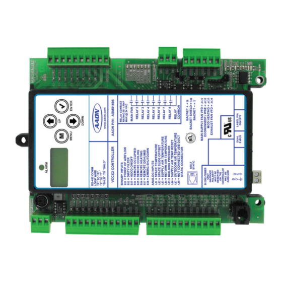
Page 12: Parts And Descriptions
OVERVIEW Parts and Descriptions PART NO. PART DESCRIPTION ILLUSTRATION PAGE NO. ASM01698 VCCX2 Controller The VCCX2 Controller provides 8 analog inputs, 4 analog outputs, 8 binary inputs, and 8 relay outputs. It also has an on-board BACnet port for connection ®... - Page 13 Page 63 an extended Leaving Air Temperature Setpoint range down to 0°F and should only be used with the approval of AAON. The Controller directly connects to the VCCX2 Controller or indirectly using an E-BUS Expansion Board via an EBC E-BUS cable.
- Page 14 OVERVIEW Parts and Descriptions PART NO. PART DESCRIPTION ILLUSTRATION PAGE NO. ASM01873 12 Relay E-BUS Expansion Module The 12 Relay Expansion Module adds 12 configurable relays to the VCCX2 Control System. It connects to the VCCX2 Controller with an EBC E-BUS cable. Pages 23, 49 ASM02227...
- Page 15 OVERVIEW Parts and Descriptions PART NO. PART DESCRIPTION ILLUSTRATION PAGE NO. ASM01840 E-BUS Return Air Temperature & Humidity Sensor Used for return air temperature and humidity sensing applications. Connects to VCCX2 Controller or E-BUS Adapter Hub using EBC E-BUS cable. Includes: E-BUS Return Air Temperature & Humidity Sensor, mounted Page 37 in a weatherproof handy box attached 3-foot EBC E-BUS Cable with jack.
- Page 16 OVERVIEW Parts and Descriptions PART NO. PART DESCRIPTION ILLUSTRATION PAGE NO. Pages Strap-on Temperature Sensor Kit ASM01624 43 & 44 Includes: 10K Ohm, Type 3, Strap-on Temperature Sensor, 2 wire. Used for water temperature sensing applications. Includes sensor, thermal mastic, and plastic mounting strap.
- Page 17 The E-BUS Return Air Temperature and Humidity Sensor Emulator Board allows the use of 3rd party analog return air temperature and humidity sensors to emulate the AAON E-BUS combination Return Air Temperature and Humidity Sensor. Includes: E-BUS Sensor Emulator Board and 1.5 foot EBC E-BUS cable.
- Page 18 8 separate 2 events per day schedules which can be assigned to any input or output for operational control or alarm recognition based on time of day. These schedules can also be configured to broadcast to other AAON HVAC equipment installed on the control system loop. Includes: GPC-XP Controller.
-
Page 19: Controller With Enclosure Components
VCCX2 OVERVIEW Controller with Enclosure Components Figure 1: VCCX2 Controller with Enclosure Components VCCX2 Controller Technical Guide... -
Page 20: Dimensions
DIMENSIONS VCCX-2 Controller NOTE: All dimensions are in inches unless otherwise noted. Figure 2: VCCX2 Controller Dimensions VCCX2 Controller Technical Guide... -
Page 21: Refrigerant System Module (Rsm) (Typical)
DIMENSIONS Refrigerant System Module (RSM) (Typical) NOTE: Typical dimensions in inches. See individual RSM Technical Guides for each RSM’s dimensions. RSMV shown. Figure 3: Typical Refrigerant System Module Dimensions (RSMV Shown) VCCX2 Controller Technical Guide... -
Page 22: Vcc-X Em1 Expansion Module
DIMENSIONS VCC-X EM1 Expansion Module NOTE: All dimensions are in inches unless otherwise noted. Figure 4: VCC-X EM1 Expansion Module Dimensions VCCX2 Controller Technical Guide... -
Page 23: 12-Relay E-Bus Module
DIMENSIONS 12-Relay E-BUS Module NOTE: All dimensions are in inches unless otherwise noted. Figure 5: 12-Relay E-BUS Module Dimensions VCCX2 Controller Technical Guide... -
Page 24: Wiring
VA rating listed in Table 1, this page. can supply communication wire that meets this specification and is color coded for the network or local loop. Please consult your AAON distributor for information. If desired, Belden #82760 or equivalent wire may also be used. -
Page 25: Vccx2 Controller Inputs
WIRING VCCX2 Controller Inputs VCCX2 Controller Inputs The VCCX2 Controller is designed with 8 analog inputs, 4 analog outputs, 8 binary inputs and 8 relay outputs. There are also 2 E-BUS Expansion Ports which allow the use of communicating sensors and the E-BUS Modules. See Figures 6, this page &... -
Page 26: Vccx2 Controller Outputs
WIRING VCCX2 Controller Outputs Figure 7: VCCX2 Controller Output Wiring VCCX2 Controller Technical Guide... -
Page 27: E-Bus Digital Room Sensor
WIRING E-BUS Digital Room Sensor E-BUS Digital Room Sensor The E-BUS Digital Room Sensor should be mounted on the wall in an area that does not have drafts or is exposed to direct The ASM01819 E-BUS Digital Room Temperature Sensor can be sunlight. -
Page 28: E-Bus Co 2 Wall-Mounted Sensor
WIRING E-BUS CO Wall-Mounted Sensor E-BUS CO2 Wall-Mounted Sensor A Duct Mounted E-BUS CO Sensor can be used if desired instead of the Wall Mounted E-BUS CO Sensor. See Figure 10, The ASM01829 Wall Mounted E-BUS CO Sensor is used to page 29 for Duct Mounted E-BUS CO Sensor wiring details. -
Page 29: Duct Mounted E-Bus Co 2 Sensor
E-BUS Hub or Adapter Board may be required. The Duct Mounted Return Air CO Sensor is comprised of the Sensor, the AAON Aspiration Box Assembly, and a Remote Pickup Tube. Figure 10: Duct Mounted E-BUS CO2 Sensor Wiring VCCX2 Controller Technical Guide... -
Page 30: Space Temperature Sensor
WIRING Space Temperature Sensor Space Temperature Sensor The Space Temperature Sensor is available as a sensor only, sensor with override button, sensor with slide adjust, and sensor The ASM02227, ASM01638, ASM01642, ASM01643 Space with slide adjust and override configurations. Temperature Sensor is typically used for constant volume HVAC See Figure 11, this page for complete Space Temperature Sensor unit applications controlling one zone. -
Page 31: Supply Air Temperature Sensor
WIRING Supply Air Temperature Sensor Supply Air Temperature Sensor The G051240 (6 inch) or G051250 (12 inch) Supply Air Temperature Sensor must be wired as shown for proper operation. The Supply Air Temperature Sensor is a 10K Type III thermistor sensor. -
Page 32: Return Air Temperature Sensor
WIRING Return Air Temperature Sensor Return Air Temperature Sensor G051240 (6 inch) or G051250 (12 inch) Return Air Temperature Sensor must be wired as shown for proper operation. The Return Air Temperature Sensor is a 10K Type III thermistor sensor. The Return Air Temperature Sensor should be mounted in the return air duct. -
Page 33: Building Pressure Sensor
WIRING Building Pressure Sensor Building Pressure Sensor It is very important to be certain that all WARNING: wiring is correct as shown in the wiring The ASM01832 Building Static Pressure Sensor must be wired as diagram below. Failure to observe the shown in Figure 14, this page. -
Page 34: Remote Sat Reset
WIRING Remote SAT Reset Remote SAT Reset Signal A Remote Supply Air Temperature Reset Signal can be connected to AI6 for applications requiring Remote Reset of the Supply Air Temperature Setpoint. See Figure 15, this page. Figure 15: Remote SAT Reset Signal Wiring Diagram VCCX2 Controller Technical Guide... -
Page 35: E-Bus Outdoor Air Temperature Sensor
WIRING E-BUS Outdoor Air Temperature Sensor Outdoor Air Temperature Sensor Be sure to mount the Outdoor Air Temperature CAUTION: Sensor in an area that is not exposed to direct The G042330 Outdoor Air Temperature Sensor must be wired sunlight. The shaded area under the HVAC as shown for proper operation of the VCCX2 Controller. -
Page 36: E-Bus Outdoor Air Temperature And Humidity Sensor
WIRING E-BUS Outdoor Air Temperature and Humidity Sensor E-BUS Horizontal or Vertical Outdoor Be sure to mount the Outdoor Air Temperature CAUTION: Air Temperature & Humidity Sensor & Humidity Sensor in an area that is not exposed to direct sunlight. The shaded area The ASM01836 (Horizontal) or ASM01838 (Vertical) E-BUS under the HVAC unit rain hood is normally Outdoor Air Temperature &... -
Page 37: E-Bus Return Air Temperature And Humidity Sensor
WIRING E-BUS Return Air Temperature and Humidity Sensor E-BUS Return Air Temperature & If using multiple E-BUS Sensors or Modules, the NOTE: Humidity Sensor E-BUS Hub (ASM01635 or G033970) or E-BUS Adapter Board (ASM01878) may be required. The ASM01840 E-BUS Return Air Temperature & Humidity Sensor connects to the VCCX2 Controller. -
Page 38: Static Pressure Transducer
WIRING Duct Static Pressure Transducer Duct Static Pressure Transducer It is strongly recommended that you use CAUTION: pneumatic tubing instead of relocating the The ASM01640 Duct Static Pressure Transducer plugs directly sensor. Extending the wires could cause into the VCCX2 Controller’s static pressure port. The Duct Static voltage drop problems. -
Page 39: Supply Fan Vfd Or Bypass Damper Actuator
WIRING Supply Fan VFD or Bypass Damper Actuator Supply Fan VFD Signal or Bypass Variable Frequency Drive units can cause CAUTION: Damper Actuator large transient noise spikes which can cause interference to be propagated on other The Supply Fan VFD signal is a user-adjustable signal with a electronic equipment. -
Page 40: Economizer Actuator Or Wse Actuator
WIRING Economizer Actuator or WSE Actuator Economizer Damper Actuator Waterside Economizer (WSE) Valve The Economizer Damper Actuator signal voltage output (using The WSE valve must be wired as shown in Figure 21, this page AO2) is user-adjustable, but must be set to 2-10 VDC for this for proper operation. -
Page 41: Modulating Heating Device
WIRING Modulating Heating Device Modulating Heating Device It is very important to be certain that all WARNING: wiring is correct as shown in the wiring The Modulating Heating Device signal voltage output is a user- diagram below. Failure to observe the adjustable signal with a range of 0-10 VDC from AO3 when correct polarity could result in damage programming the controller. -
Page 42: Building Pressure Control Outputs
WIRING Building Pressure Control Outputs Building Pressure Control Output When using the OA damper for Reverse Building Pressure Control, the output signal must be configured for reverse acting The ASM01832 Building Pressure Control Output is a 0-10 VDC operation. A building pressure sensor connected to AI5 on the or 2-10 VDC signal sent from the VCCX2 Controller. -
Page 43: Entering H 2 0 Temp Sensor, Ra Plenum, And Return/Exhaust Fan Proving
WIRING Entering H 0 Temp Sensor, RA Plenum, and Return/Exhaust Fan Proving VCC-X Expansion Module EM1 Return Air Plenum Pressure Sensor The VCC-X EM1 Expansion Module connects to the VCCX2 The ASM01832 Return Air Plenum Pressure Sensor (also used Controller with an EBC E-BUS cable and adds an additional: as a Building Static Pressure Sensor, as shown on page 33) five analog inputs, five analog outputs, three binary inputs, and must be wired as shown in Figure 24, this page. -
Page 44: Vcc-X Em1 Entering Water Temperature Sensor
WIRING VCC-X EM1 Entering Water Temperature Sensor Figure 25: Entering Water Temperature Sensor Location VCCX2 Controller Technical Guide... -
Page 45: Vcc-X Em1 Expansion Module Inputs
WIRING VCC-X EM1 Expansion Module Inputs Exhaust Duct Static Pressure Sensor Observe Polarity! All boards must be WARNING: The ASM01640 Static Pressure Transducer plugs directly into wired with GND-to-GND and 24VAC-to- 24VAC. Failure to observe polarity will the EM1’s Static Pressure port. The Duct Static Pressure Sensor result in damage to one or more of the reading is used to determine current Exhaust Duct Static Pressure. -
Page 46: Vcc-X Em1 Expansion Module Outputs
WIRING VCC-X EM1 Expansion Module Outputs VCC-X EM1 Expansion Module Outputs Observe Polarity! All boards must be WARNING: wired with GND-to-GND and 24VAC-to- The VCC-X EM1 Expansion Module must be connected to 24 24VAC. Failure to observe polarity will VAC as shown in the wiring diagram below. Please see Table result in damage to one or more of the 1, page 24 for correct VA requirements to use when sizing the boards. -
Page 47: Chilled Water Valve Actuator
VCC-X EM1 Expansion Module RELAY OUTPUT TERMINALS Chilled Water VCC-X E EXPANSION Valve Actuator AAON P/N: ASM01691 ANALOG OUTPUT TERMINALS CHILLED WATER RETURN DAMPER RETURN BYPASS AOUT1 NOT USED NOT USED NOT USED POWER INPUT... -
Page 48: Return Air Bypass
Return Air Bypass It is very important to be certain that all WARNING: wiring is correct as shown in the wiring The VCCX2 Controller can be configured for AAON Return Air ® diagram below. Failure to observe the Bypass applications. These provide improved moisture removal... -
Page 49: 12-Relay E-Bus Expansion Module
WIRING 12-Relay E-BUS Expansion Module 12-Relay E-BUS Expansion Module A total of 17 relays are available by adding the NOTE: Relay Expansion Modules. All Expansion Module The ASM01873 E-BUS 12-Relay Expansion Module provides relay outputs are user-configurable. for 12 Dry Contact Configurable Relay Outputs. See Figure 30, this page for complete wiring details. -
Page 50: Ebtron ® , Greentrol Tm , And Paragon Digital Transmitters
Adapter Board. of MODBUS RTU transmitters are compatible with the VCCX2 Controller. No other series of transmitters will work for this application. Contact AAON Controls for information on other airflow If using multiple E-BUS Sensors or Modules, the NOTE: station options. -
Page 51: Rsmv Controller Inputs
WIRING RSMV Controller Inputs Refrigerant System Module for VFD • Modulates the Condenser Fan to maintain the Head Pressure Setpoint. Compressors Wiring • Modulates the Expansion Valves to maintain the The ASM01686 Refrigerant System Module for VFD Compressors Superheat Setpoint. (RSMV) monitors and controls one tandem refrigeration circuit of •... -
Page 52: Rsmv Controller Outputs
WIRING RSMV Controller Outputs Suction Pressure Sensor Wiring The Shraeder port used for installation of the CAUTION: The ASM02222 Suction Pressure Transducer must be wired as suction pressure transducer should be located shown in Figure 32, page 51. It is required for all compressorized in a vertical position of the suction line to VCCX2 applications. -
Page 53: Wiring
WIRING RSMV-HP Controller Inputs Refrigerant System Module for VFD The Suction Pressure Sensors are used to measure suction pressure at the HVAC unit’s DX evaporator coil suction line. Compressors - Heat Pump Wiring This suction line pressure is converted to saturated refrigerant temperature. -
Page 54: Rsmv-Hp Controller Outputs
WIRING RSMV-HP Controller Outputs Coil Temperature Sensors The Shraeder port used for installation of the CAUTION: The Coil Temperature Sensors are used to measure Coil suction pressure transducer should be located Temperature after each evaporator coil line. This temperature in a vertical position of the suction line to combined with the calculated saturated refrigerant temperature prevent refrigerant oil from accumulating in is used to calculate the Superheat of each individual evaporator... -
Page 55: Rsmd Controller Inputs
WIRING RSMD Controller Inputs Refrigerant System Module for Digital Suction Pressure Sensor Wiring Compressors Wiring The ASM02222 Suction Pressure Transducers must be wired as shown in Figure 36, this page. It is typically required for all The ASM02201 Refrigerant System Module for Digital VCCX2 applications. -
Page 56: Rsmd Controller Outputs
WIRING RSMD Controller Outputs Head Pressure Control The Shraeder port used for installation of the CAUTION: The Head Pressure Transducers are used to measure Head suction pressure transducer should be located Pressure at the discharge line. This Head Pressure is used to drive in a vertical position of the suction line to the Condenser Fans with a 0-10 VDC output signal to maintain prevent refrigerant oil from accumulating in... -
Page 57: Rsmz Controller Inputs
WIRING RSMZ Controller Inputs RSMZ Controller Input Wiring The RSMZ Controller must be connected to an 18-30 VAC power source. When wiring the RSMZ Controller, its relay outputs must The ASM02351 Refrigerant System Module for VFD Comp- be wired as wet contacts (connected to 24 VAC). See Figure 38, ressors (RSMZ) monitors and controls one refrigeration circuit this page for input wiring. -
Page 58: Rsmz Controller Outputs
WIRING RSMZ Controller Outputs RSMZ Controller Output Wiring • Monitors the performance of the DMQ Universal Superheat Controller/Sensor (USHX) to maintain the The RSMZ Controller provides the following features: Superheat Setpoint of each evaporator coil. • Modulates the Compressors to satisfy the Suction Coil •... -
Page 59: Subcool Monitor Controller
WIRING Subcool Monitor Controller Subcool Monitor Controller Wiring The Subcool Monitor Controller contains a 2 x 8 LCD character display and four buttons that allow for configuration, status, The ASM02350 Subcool Monitor Controller reads the liquid and alarm display. This module must be configured to work line pressure and then converts it to saturated liquid temperature with R410A refrigerant and configured for 667 PSI liquid line and compares it to the measured liquid line temperature to... -
Page 60: Mhgrv-X Controller
WIRING MHGRV-X Controller MHGRV-X Controller Wiring The following information will be passed between the MHGRV-X controller and the VCCX2 Controller: The ASM01670 MHGRV-X Controller is designed to control a • Reheat Enable command Modulating Hot Gas Reheat Valve to maintain a desired Supply •... -
Page 61: Modgas-X Controller
WIRING MODGAS-X Controller MODGAS-X Controller Wiring The following information will be passed between the MODGAS-X controller and the VCCX2 Controller: The ASM01668 MODGAS-X Controller is designed to • Heat activation command modulate up to two gas valves to maintain a desired Discharge •... -
Page 62: Modgas-Xwr2 Controller
WIRING MODGAS-XWR2 Controller MODGAS-XWR2 Controller Wiring The following information will be passed between the MODGAS- XWR2 Controller and the VCCX2 Controller: The ASM01695 MODGAS-XWR2 Controller is designed to • Heat activation command be used with White-Rogers valves only. It will modulate up to ®... -
Page 63: Preheat-X And Preheat-X-Ext Controller
The PREHEAT-X-EXT Controller has an extended Leaving Air Temperature Setpoint range down to 0°F. It should only be used • Alarm Status with the approval of AAON. • If the communication is interrupted between the PREHEAT-X Controller and the VCCX2 Controller, Either PREHEAT-X Controller directly connects to the VCCX2 the PREHEAT-X Controller will be disabled. -
Page 64: Start - Up And Commissioning
START - UP AND COMMISSIONING Powering Up and Configuration Before Applying Power If using the System Manager TS-L for monitoring, please see the System Manager TS-L Technical Guide. In order to have a trouble free start-up, it is important to follow a No matter which operator interface you use, we recommend that few simple procedures. -
Page 65: Inputs And Outputs
INPUTS AND OUTPUTS VCCX2 Controller and EM1 Module Input/Output Maps Input/Output Map Binary Outputs (24 VAC) Fan Relay (RLY1) See Table 2, this page for VCCX2 Controller Input/Outputs and Table 3 for VCC-X EM1 Inputs/Outputs. For the RSM Module Configurable Relay (RLY2) Input/Output tables, please see each individual RSM Module Configurable Relay (RLY3) Technical Guide. -
Page 66: Vccx2 Controller Inputs
INPUTS AND OUTPUTS VCCX2 Controller Inputs VCCX2 Controller Inputs The other available control method is to configure one of the Output Relays as an Exhaust Fan output that will activate the Exhaust Fan any time the Building Pressure is above the Building AI1 - Space Temperature Sensor Input Pressure Setpoint. -
Page 67: Vccx2 Controller Outputs
INPUTS AND OUTPUTS VCCX2 Controller Outputs VCCX2 Controller Outputs BIN3 - Hood On/Off Input When this wet contact input closes (Hood On), the VCCX2 AO1 - Main Supply Fan VFD Control Signal or Controller switches from Indoor Air Control to Outdoor Air Bypass Damper Control Signal Control. -
Page 68: Vcc-X Em1 Expansion Module
Return Air Bypass Damper Actuator Waterside Economizer operation. If the unit is in Cooling Mode in conjunction with a Return Air Damper Actuator for AAON ® and the Entering Water Temperature drops 10˚F (adj.) below the PAC or DPAC control applications. -
Page 69: E-Bus 12-Relay Expansion Module
INPUTS AND OUTPUTS E-BUS 12-Relay Expansion Module Relay Description Details Cooling Stage Configured for each fixed stage of cooling (except heat pump compressor). Heating Stage Configured for each fixed stage of heating. Aux Heat Configured for a fixed stage of Aux Heat in a heat pump unit. Emergency Heat Configured for a fixed stage Emergency Heat in a heat pump unit. -
Page 70: Sequence Of Operations
SEQUENCE OF OPERATIONS Supply Fan and Occupied/Unoccupied Operation Supply Fan Operation Supply Air Tempering—Selected for VAV units maintaining a Cooling Setpoint with Cooling or Heating as required that may Any time the Supply Fan is requested to start, a one-minute need heat to temper the Supply Air Temperature during very minimum off timer must be satisfied. -
Page 71: Hvac Modes Of Operation
SEQUENCE OF OPERATIONS HVAC Modes of Operation Internal Week Schedule If the OAT disables mechanical cooling while it is currently operating, mechanical cooling will stage off as minimum run An Internal Week Schedule, which supports up to two start/stop times and stage down delays are satisfied. events per day and allows scheduling of up to 14 holiday periods per year is available for determining Occupied and Unoccupied If the economizer is enabled, it will function as the first stage of... - Page 72 SEQUENCE OF OPERATIONS HVAC Modes of Operation Cooling stages will continue to run until the SAT falls below the Active Supply Air Temperature Setpoint minus the Cooling Stage Control Window at which point the cooling will begin to stage off. Each stage must meet its Minimum Run Time (adj.) before it is allowed to stage off and successive stages are subject to a Cooling Stage Down Delay (adj.).
-
Page 73: Economizer Operation
SEQUENCE OF OPERATIONS Economizer Operation Economizer Operation (Standard) Economizer Override Via BACnet ® As stated above, the economizer must reach and remain at 100% For Waterside Economizer Operation, see page NOTE: before compressors will be allowed to stage on to meet the Cooling Supply Air Setpoint. -
Page 74: Dehumidification Mode
SEQUENCE OF OPERATIONS Dehumidification Mode Dehumidification Mode Do not use this option on a MUA unit that does NOTE: not have return air and which is not configured for On VAV, CAV, Single Zone VAV, and High Percentage Outdoor space controlled Night Setback operation. Damage Units with Space Temperature Control, the Dehumidification to the unit could occur since the OA damper Mode is initiated when the Indoor Humidity rises above the... -
Page 75: Reheat, Coil Suction, And Return Air Bypass Damper
Damper Factor setpoint. If you want less air to pass through the these applications to avoid warranty and/ RAB Damper, enter a smaller number in the Return Air Damper or rating problems. AAON assumes no Factor setpoint. liability for any Simultaneous Heating and... -
Page 76: Heating Mode
SEQUENCE OF OPERATIONS Heating Mode Heating Mode The minimum signal adjustment per Time Period is based on the Modulating Heating Proportional Window. The larger the Available heating options are Staged Gas, Modulating Gas, Modulating Heating Proportional Window, the smaller the signal Staged Electric, On/Off Hot Water, Modulating Hot Water, and adjustment will be per Time Period. -
Page 77: Ventilation Mode, Remote Contact Control, And Space Sensor Operation
SEQUENCE OF OPERATIONS Ventilation Mode, Remote Contact Control, and Space Sensor Operation Remote Contact Control Primary and Secondary Heating The VCCX2 can activate two forms of Heating, which are A Remote Contact Control option can be configured on the classified as Primary and Secondary Heat Sources. The following VCCX2 Controller to initiate the HVAC Modes of operation. - Page 78 SEQUENCE OF OPERATIONS Ventilation Mode, Remote Contact Control, and Space Sensor Operation Multiple Digital Space Sensors Multiple (up to 10) digital space sensors can be connected to the VCCX2 Controller in applications where multiple spaces (not utilizing VAV boxes) could be served by a single unit. These sensors can be either the E-BUS Digital Space Temperature Sensor or the E-BUS Digital Combo Space Temperature/ Humidity Sensor.
-
Page 79: Iaq Control, Morning Warm-Up And Cool-Down, And Single Zone Vav
SEQUENCE OF OPERATIONS IAQ Control, Morning Warm-Up and Cool-Down, and Single Zone VAV IAQ (CO ) Control Operation If you have stand-alone VAV boxes that need to be forced wide open during the Warm-Up Mode, you can configure one of the If you have configured the VCCX2 Controller to monitor and relay outputs to be used during this Mode. - Page 80 SEQUENCE OF OPERATIONS IAQ Control, Morning Warm-Up and Cool-Down, and Single Zone VAV Supply Air Temperature Setpoint Reset In the Cooling Mode, the modulating cooling source will modulate to maintain the Cooling Supply Air Setpoint. The Various sources can be configured to reset the Supply Air Supply Fan VFD will begin operation at a user-adjustable Temperature (SAT) Setpoint.
-
Page 81: Airflow Monitoring, Pre-Heater, Low Ambient And Duct Static Press
GreenTrol GF series of airflow station. Percentage Outdoor Air, and the unit is in Outdoor Air Vent Mode, Contact AAON Controls for information on other airflow station the wheel is disabled. The controller can also be configured to options. -
Page 82: Duct Static Setpoint Reset And Duct Static Pressure Control
Static Sensor is installed, however, no control will occur. Duct Static Setpoint Reset If the VCCX2 Controller is being used with AAON VAV box controllers in a VAV system, the Duct Static Pressure Setpoint can be dynamically reset based on the most-open VAV box associated with that unit. -
Page 83: Building Pressure Control And Exhaust Duct Static Pressure Control
The VCCX2 can maintain Building Static Pressure anytime the using this option. Contact AAON if you have questions. Supply Fan is operating. A Building Pressure Transducer must If this option is selected, the Supply Fan VFD Output be connected to the VCCX2 Controller. -
Page 84: Mua, Cav/Mua, And Space Temperature Control
SEQUENCE OF OPERATIONS MUA, CAV/MUA, and Space Temperature Control MUA Operation Space Temperature Control of High Percentage Outdoor Air Units Occupied Mode—The VCCX2 will use the normal Cooling and Heating Mode Enable Setpoints (not the Hood On Setpoints) in This option allows for Space Temperature control of 100% conjunction with the Outdoor Air (OA) temperature sensor to Outdoor Air MUA Units or units with a high percentage of determine the mode of operation. -
Page 85: Vav W/Sa Tempering, Air To Air Heat Pump And Standard Defrost
SEQUENCE OF OPERATIONS VAV w/SA Tempering, Air to Air Heat Pump and Standard Defrost VAV Operation with Supply Air In this operation, if Night Setback operation will be initiated by a space sensor connected to the VCCX2 Controller, then the Tempering (VAV Operation with Night Setback Cooling and Heating Offsets will be applied to Outdoor Air Temperature Control) -
Page 86: Heat Pump Adaptive Defrost, Wshp, Exv And Head Pressure
SEQUENCE OF OPERATIONS Heat Pump Adaptive Defrost, WSHP, EXV and Head Pressure In the Defrost Cycle, the reversing valve signal is switched to the At that point, the Auxiliary Heat will stage off (after a stage opposite operation, and the compressors are brought to maximum down delay) and the digital compressor heat will be allowed to capacity. -
Page 87: Evaporative Condenser, Wse, Oa Lockouts And Temp Protection
SEQUENCE OF OPERATIONS Evaporative Condenser, WSE, OA Lockouts and Temp Protection Evaporative Condenser Operation Unit Cooling Mode If in the Cooling Mode, the Entering Water Temperature is below If the unit has been configured for Evaporative Condenser Control the Entering Air Temperature (measured by the sensor connected and the Outdoor Air Temperature is above the Evaporative/ to the Outdoor Temperature Sensor input), by the Entering Modulating Condenser Low Ambient Setpoint, the Evaporative... - Page 88 SEQUENCE OF OPERATIONS Evaporative Condenser, WSE, OA Lockouts and Temp Protection Outdoor Air Lockouts The compressors are disabled during Cooling Mode when the Outdoor Air Temperature is below the Compressor Cooling Lockout Setpoint. Mechanical heating is disabled when the Outdoor Air Temperature is above the Heating Lockout Setpoint.
-
Page 89: Alarm Detection And Sensor Failure Alarms
SEQUENCE OF OPERATIONS Alarm Detection and Sensor Failure Alarms Alarm Detection and Reporting Sensor Failure Alarms The VCCX2 Controller continuously performs self diagnostics Supply Air Temperature Sensor Failure Alarm during normal operation to determine if any operating failures The Supply Air Temperature Sensor Failure Alarm is generated have occurred. - Page 90 SEQUENCE OF OPERATIONS Alarm Detection and Sensor Failure Alarms If the controller is configured to have any of the above air flow sensors, but the controller does not detect that the sensor is connected, then the applicable alarm will occur. If the sensor is properly detected after the unit has alarmed, the alarm will be cleared.
-
Page 91: Mechanical Failure And Failure Mode Alarms
SEQUENCE OF OPERATIONS Mechanical Failure and Failure Mode Alarms Mechanical Failure Alarms Dirty Filter Alarm A differential pressure switch is used to provide a 24 VAC wet Mechanical Cooling Failure contact closure to indicate a dirty filter status. A Dirty Filter Alarm is then generated. -
Page 92: Title 24 Economizer Alarms
SEQUENCE OF OPERATIONS Title 24 Economizer Alarms RSM Module (1-4) Operating Alarm This alarm indicates numerous alarm conditions. Please refer to the individual RSM Technical Guides for details. Title 24 (FDD) Economizer Alarms Economizer Temperature Sensor Failure Outside Air or Supply Air Temperature Sensor is shorted or missing. -
Page 93: Vccx2 Controller Trend Logs
SEQUENCE OF OPERATIONS VCCX2 Controller Trend Logs RSM Trend Logs VCCX2 CONTROLLER TREND LOGS Item Description Log Abbreviation There can be as many as four RSMV or RSMDs on a unit, or (Unit) six RSMZs, with each RSM controlling up to two compressors Date Date (Day Month) and condensers. -
Page 94: Rsmv/Rsmd/Rsmz Trend Logs And Trend Log Enumerated Values
SEQUENCE OF OPERATIONS RSMV/RSMD/RSMZ Trend Logs and Trend Log Enumerated Values RSMV / RSMD MODULE TREND LOGS TREND LOG ENUMERATED VALUES (TYPICAL OF 4 RSM MODULES) Item Description Value Description Item Description Log Abbreviation (Unit) Unoccupied Condenser A1 Superheat 1SprHeat3 (ºF) Occupied Mode Push Button Override Active... -
Page 95: Rsmz Trend Logs And Trend Log Enumerated Values
SEQUENCE OF OPERATIONS RSMZ Trend Logs and Trend Log Enumerated Values RSMZ TREND LOG BIT STRINGS - COMPSTAT Item Bit Value Description Configured Enabled Running Failed Lockout 1Comp1Stat 2Comp1Stat MinRunFlag 3Comp1Stat MinRunPending 3Comp2Stat 4Comp1Stat MinOffFlag 5Comp1Stat MinOffPending 6Comp1STat 6Comp2Stat StageUpConditionsMet 1024 StageDwnConditionsMet 2048... -
Page 96: Table 11: Rsmz Module Vfd Status Trend Log
SEQUENCE OF OPERATIONS RSMZ Trend Logs and Trend Log Enumerated Values RSMZ TREND LOG BIT STRINGS - VFD STATUS Item Value VFD Status (Bit = 0) VFD Status (Bit = 1) 0 = Control Not Ready 1 = Control Ready 0 = Drive Not Ready 1= Drive Ready 0 = Coasting... -
Page 97: Trend Log Bit String Decoding
SEQUENCE OF OPERATIONS Trend Log Bit String Decoding Trend Log Bit String Decoding RSMZ VFD Status Decoding For the RSMZ VFD status, instead of just one set of bit string Bit String values allow the manipulation of binary data in useful values, there are two. -
Page 98: Table 14: Vccx2 Trend Log Bit Strings
SEQUENCE OF OPERATIONS Trend Log Bit String Decoding VCCX2 TREND LOG BIT STRINGS VCCX2 TREND LOG BIT STRINGS Item Value Description Item Value Description Bad Supply Sensor Missing Refrigeration Module 1 Bad Return Sensor Missing Refrigeration Module 2 Bad Outdoor Air Sensor Missing Refrigeration Module 3 Bad Space Sensor Missing Refrigeration Module 4... -
Page 99: Table 14: Vccx2 Trend Log Bit Strings (Continued)
SEQUENCE OF OPERATIONS Trend Log Bit String Decoding VCCX2 TREND LOG BIT STRINGS Item Value Description 12 Relay Exp Relay #1 Configurable 12 Relay Exp Relay #2 Configurable 12 Relay Exp Relay #3 Configurable 12 Relay Exp Relay #4 Configurable 12 Relay Exp Relay #5 Configurable 12 Relay Exp Relay #6... -
Page 100: Troubleshooting
TROUBLESHOOTING VCCX2 Controller and EM1 LED Diagnostics VCCX2 Controller LEDs RLY2 - RLY8 - These green LEDs will light up when the relays are enabled and will stay lit as long as they are active. The VCCX2 Controller is equipped with LEDs that can be used to verify operation and perform troubleshooting. -
Page 101: Figure 46: Vccx2 Controller Led Locations
TROUBLESHOOTING VCCX2 Controller and EM1 LED Diagnostics Figure 46: VCCX2 Controller LED Locations Figure 47: VCC-X EM1 Expansion Module LED Locations VCCX2 Controller Technical Guide... -
Page 102: Temperature Sensor Testing
TROUBLESHOOTING Temperature Sensor Testing Space, Supply Air, Outdoor Air or Thermistor Sensor Testing Instructions Return Air Temperature Sensor Use the resistance column to check the thermistor sensor while Testing disconnected from the controllers (not powered). Use the voltage column to check sensors while connected to The following sensor voltage and resistance table is provided to powered controllers. -
Page 103: Duct Static Pressure And Building Pressure Sensor Testing
TROUBLESHOOTING Duct Static Pressure and Building Pressure Sensor Testing Duct Static Pressure Sensor Testing Building Pressure Sensor Testing The table below is used to troubleshoot the Duct Static Pressure The table below is used to troubleshoot the Building Pressure Sensors. Sensors. -
Page 104: Appendix A - System Configuration
48, this page. The available Operator Interfaces are as follows: If you have 1 to 59 VCCX2 Controllers that require information sharing, simply connect the controllers together using AAON • Modular Service Tool SD communications wire or 18-gauge, 2-conductor twisted pair •... -
Page 105: Stand-Alone System Layout
APPENDIX A - SYSTEM CONFIGURATION Stand-Alone System Layout Figure 49: Typical Stand-Alone System Layout VCCX2 Controller Technical Guide... -
Page 106: Interconnected System Layout
APPENDIX A - SYSTEM CONFIGURATION Interconnected System Layout Figure 50: Typical Interconnected System Layout VCCX2 Controller Technical Guide... -
Page 107: Networked System Single Loop Layout
APPENDIX A - SYSTEM CONFIGURATION Networked System Single Loop Layout Figure 51: Typical Networked Single Loop System Layout VCCX2 Controller Technical Guide... -
Page 108: Appendix B - Vccx2 Lcd Screens
APPENDIX B - VCCX2 LCD SCREENS Navigation Keys LCD Display Screen & Navigation Keys Navigation Key Function The LCD display screens and buttons allow you to view status and alarms, enable force modes, and make BACnet configuration ® MENU Use the MENU key to move through screens within Main Menu categories and return to the changes. -
Page 109: Main Screens Map
APPENDIX B - VCCX2 LCD SCREENS Main Screens Map Main Screens Map Output Override Refer to the following map when navigating through the Main Screens. The first screen is an initialization screen. To scroll through the rest of the screens, press the <MENU> button. Press to scroll through Output Override Screens. -
Page 110: Setting Screens
APPENDIX B - VCCX2 LCD SCREENS Setting Screens Settings Screens Refer to the following map when navigating through the Settings DEVICEID Screens. From the Settings Screen, press <ENTER> to scroll XXXXXXX through the screens. Settings BACnet ® - CURRENT DEVICE ID A Device ID of up to 7 digits can be entered. -
Page 111: Status Screens
APPENDIX B - VCCX2 LCD SCREENS Status Screens Status Screens Refer to the following map when navigating through the Status Screens. From the Status Screen, press <ENTER> to scroll Spc RH through the screens. X.X % Status SPACE HUMIDITY 0.00% - 100% OPER MODE Sat Temp UNOCCUPY... -
Page 112: Alarm Screens
APPENDIX B - VCCX2 LCD SCREENS Alarm Screens Alarm Screens If there are no Alarms, the Alarm Screen will display “No Alarms.” If there are alarms present, the screen will display, “Alarms.” You can press <ENTER> to scroll through the alarms or you can let the alarms automatically scroll on the screen. -
Page 113: Output Override Screens
APPENDIX B - VCCX2 LCD SCREENS Output Override Screens Output Override Screens Refer to the following map when navigating through the Output Override Screens. From the Output Override Screen, press Exhaust <ENTER>. -1.0, 0.0-10.0 Output Override EXHAUST FAN 0.0 to 10.0 = Active Force Mode. <UP>... -
Page 114: Air Balance Screens And Factory Test Mode Screen
APPENDIX B - VCCX2 LCD SCREENS Air Balance Screens and Factory Test Mode Screen Air Balance Screens Refer to the following map when navigating through the Air Balance Screens. From the Air Balance Screen, press <ENTER>. Max Exh 10.0 vdc MAXIMUM EXHAUST VOLTAGE Balance 0.0 to 10.0 vdc... -
Page 115: Appendix C - Vccx2 Bacnet
APPENDIX C - VCCX2 BACnet ® VCCX2 BACnet Parameters ® VCCX2 CONTROLLER ALARM MENU ENTER Programming Note: DOWN Use Settings Menu in the LCD display ® to program the BACnet ettings. MS/TP Connection ® To BACnet Network Typical Terminal Blocks. All Wiring To Be R+ To R+, SH (G) To SH (G) &... - Page 116 APPENDIX C - VCCX2 BACnet ® VCCX2 BACnet Parameters ® BACnet Properties for the VCCX2 Controller ® Objects labeled AI and BI are read-only. Objects NOTE: labeled AV are read/writeable. The only Sensor Parameter Object Description Limits values that can be written to are AV points 72 & Outdoor Air AI: 16 Current value of the...
- Page 117 APPENDIX C - VCCX2 BACnet ® VCCX2 BACnet Parameters ® BACnet Properties for the VCCX2 Controller BACnet Properties for the VCCX2 Controller ® ® Parameter Object Description Parameter Object Description Limits Limits Modulating AI: 35 Current percentage of the A2 Suction AI: 55 Current Compressor A2 Heat Position...
- Page 118 APPENDIX C - VCCX2 BACnet ® VCCX2 BACnet Parameters ® BACnet Properties for the VCCX2 Controller BACnet Properties for the VCCX2 Controller ® ® Parameter Object Description Parameter Object Description Limits Limits B2 Discharge AI: 92 Current Compressor B2 B2 Suction AI: 74 Current Compressor B2 Temperature...
- Page 119 APPENDIX C - VCCX2 BACnet ® VCCX2 BACnet Parameters ® BACnet Properties for the VCCX2 Controller BACnet Properties for the VCCX2 Controller ® ® Parameter Object Description Limits Parameter Object Description Limits Condenser AI: 111 Current Compressor C2 D1 Condens- AI: 131 Current Compressor D1 C2 Superheat...
- Page 120 APPENDIX C - VCCX2 BACnet ® VCCX2 BACnet Parameters ® BACnet Properties for the VCCX2 Controller BACnet Properties for the VCCX2 Controller ® ® Parameter Object Description Limits Parameter Object Description Limits Current AI: 150 Current status of the RSMZ 1 AI: 164 Current RSMZ 1 Duct Static...
- Page 121 APPENDIX C - VCCX2 BACnet ® VCCX2 BACnet Parameters ® BACnet Properties for the VCCX2 Controller BACnet Properties for the VCCX2 Controller ® ® Parameter Object Description Parameter Object Description Limits Limits RSMZ 2 AI: 178 Current RSMZ 2 See RSMZ RSMZ 3 AI: 192 Current RSMZ 3...
- Page 122 APPENDIX C - VCCX2 BACnet ® VCCX2 BACnet Parameters ® BACnet Properties for the VCCX2 Controller BACnet Properties for the VCCX2 Controller ® ® Parameter Object Description Limits Parameter Object Description Limits RSMZ 4 AI: 206 Current RSMZ 4 RSMZ 5 AI: 220 Current RSMZ 5 Superheat...
- Page 123 APPENDIX C - VCCX2 BACnet ® VCCX2 BACnet Parameters ® BACnet Properties for the VCCX2 Controller BACnet Properties for the VCCX2 Controller ® ® Parameter Object Description Parameter Object Description Limits Limits RSMZ 6 AI: 234 Current RSMZ 6 RSMZ 6 AI: 248 Current RSMZ 6 See RSMZ...
- Page 124 APPENDIX C - VCCX2 BACnet ® VCCX2 BACnet Parameters ® BACnet Properties for the VCCX2 Controller BACnet Properties for the VCCX2 Controller ® ® Parameter Object Description Limits Parameter Object Description Limits SUB 2 AI: 266 Current Subcooling Occupied AV: 2 If the control tempera- 1°F 110°F...
- Page 125 APPENDIX C - VCCX2 BACnet ® VCCX2 BACnet Parameters ® BACnet Properties for the VCCX2 Controller BACnet Properties for the VCCX2 Controller ® ® Parameter Object Description Limits Parameter Object Description Limits Mechanical AV: 19 Mechanical Cooling will -30°F 100°F Min Coil AV: 9 This is the lowest that the...
- Page 126 APPENDIX C - VCCX2 BACnet ® VCCX2 BACnet Parameters ® BACnet Properties for the VCCX2 Controller BACnet Properties for the VCCX2 Controller ® ® Parameter Object Description Limits Parameter Object Description Limits PreHeat AV: 29 If the Supply Fan is -30°F 70°F SAT Cool...
- Page 127 APPENDIX C - VCCX2 BACnet ® VCCX2 BACnet Parameters ® BACnet Properties for the VCCX2 Controller BACnet Properties for the VCCX2 Controller ® ® Parameter Object Description Limits Parameter Object Description Limits Indoor AV: 53 On indoor controlled (non Minimum AV: 45 In Single Zone VAV Humidity...
- Page 128 APPENDIX C - VCCX2 BACnet ® VCCX2 BACnet Parameters ® BACnet Properties for the VCCX2 Controller BACnet Properties for the VCCX2 Controller ® ® Parameter Object Description Limits Parameter Object Description Limits Dehum Mode AV: 64 Head Pressure Setpoint in the Space AV: 73 If the controller is...
- Page 129 APPENDIX C - VCCX2 BACnet ® VCCX2 BACnet Parameters ® BACnet Properties for the VCCX2 Controller BACnet Properties for the VCCX2 Controller ® ® Parameter Object Description Parameter Object Description Limits Limits High Level AV: 80 Reserved Return Air AV: 92 If the Return Air Enthalpy High Limit...
- Page 130 APPENDIX C - VCCX2 BACnet ® VCCX2 BACnet Parameters ® BACnet Properties for the VCCX2 Controller BACnet Properties for the VCCX2 Controller ® ® Parameter Object Description Parameter Object Description Limits Limits Remote BI: 10 Remote Forced Heating Fan Proving BI: 24 Alarm that indicates an Forced...
- Page 131 APPENDIX C - VCCX2 BACnet ® VCCX2 BACnet Parameters ® BACnet Properties for the VCCX2 Controller BACnet Properties for the VCCX2 Controller ® ® Parameter Object Description Parameter Object Description Limits Limits Low Control BI: 37 Occurs when the On Board BI: 54 Current Status of Mode Alarm...
- Page 132 APPENDIX C - VCCX2 BACnet ® VCCX2 BACnet Parameters ® BACnet Properties for the VCCX2 Controller BACnet Properties for the VCCX2 Controller ® ® Parameter Object Description Limits Parameter Object Description Limits Preheater BI: 73 Status of Preheater B1-2 Defrost BI: 93 Outside Coil B1/B2 Temp Emergency...
- Page 133 APPENDIX C - VCCX2 BACnet ® VCCX2 BACnet Parameters ® BACnet Properties for the VCCX2 Controller BACnet Properties for the VCCX2 Controller ® ® Parameter Object Description Limits Parameter Object Description Limits Refrigerant BI: 112 Current Status of Compressor BI: 133 Current Run Status of Module 3 Relay #5...
- Page 134 APPENDIX C - VCCX2 BACnet ® VCCX2 BACnet Bitfields ® VCCX2 RSMZ BACnet Property RSMZAlarms1StatusBits ::= ENUMERATED { ® Identifier Brake Check Pwr. Card Temp (1), BACNETPropertyIdentifier : Earth Fault (2), RSMZWarningsStatusBits ::= ENUMERATED { Ctrl.Card Temp (3), Ctrl. Word TO (4), Low Suction Pressure (0),...
- Page 135 APPENDIX C - VCCX2 BACnet ® VCCX2 BACnet Bitfields ® RSMZAlarms2StatusBits ::= ENUMERATED { RSMZDriveStatusBits ::= ENUMERATED { Service Trip Read/Write Control_Ready (0=Control Not Ready; 1=Control Ready) Service Trip (Reserved) (1), Drive_Ready (0=Drive Not Ready; Service Trip Type Code/Spare Part (2), 1=Drive Ready) (1),...
- Page 136 ® VCCX2 BACnet PICS ® BACnet Protocol Implementation Conformance Statement ® Date: December 2017 Vendor: AAON, Inc. Product: VCCX2 Controller Product Model Number: ASM01698 Product Version: 1.13 Product Description: HVAC Unit Controller BACnet Protocol Revision: Revision 12 (ANSI/ASHRAE Standard 135-2010) ®...
-
Page 137: Index
INDEX 12 Relay E-BUS Expansion Module ........... Described ..................E-BUS CO2 Wall-Mounted Sensor ..........Described ..................E-BUS Digital Room Sensor ............Airflow Monitoring & Control ........... E-BUS Digital Room Sensor - Temp. Only Alarm Active Relay Described ..................Description ................. E-BUS Outdoor Air Temperature &... - Page 138 INDEX LCD Display Screen OE365-15-EBA ................VCC-X ..................OE366 .................... Low Ambient Operation ............. OE377-26-00058 ................Low Ambient Relay OE391-12 ..................Description ................. OE392-06 ..................OE415-02 ..................OE508 .................... Outdoor Air Temperature & Humidity Sensor ....Main Screens Map Outdoor Air Temperature Sensor ..........VCC-X ..................
- Page 139 INDEX Description ................. Static Pressure ................Static Pressure Pick-up Tube ............Described ..................Status Screens VCC-X ..................Strap-on Temperature Sensor Kit ..........Suction Pressure Sensor Wiring ..........Suction Pressure Transducer Kit Described ..................Suction Pressure Transducer Kit with E-BUS Adapter ... Supply Air Temperature ..............
- Page 140 PARTS: For replacement parts please contact your local AAON Representative. 2425 So. Yukon Ave • Tulsa, OK • 74107-2728 Ph: (918) 583-2266 • Fax: (918) 583-6094 AAON P/N: G039840, Rev. Q ® Printed in the USA • © March 2021 AAON • All Rights Reserved...
Need help?
Do you have a question about the Orion VCCX2 and is the answer not in the manual?
Questions and answers