Table of Contents
Advertisement
Advertisement
Table of Contents

Subscribe to Our Youtube Channel
Related Manuals for AAON V12100 MHGRV-X


Summary of Contents for AAON V12100 MHGRV-X
- Page 1 Factory Packaged Controls MHGRV-X Controller Field Technical Guide...
-
Page 2: Table Of Contents
Manual Part No.: V16950, Rev. 01M ® Toll Free Phone: 866-918-1100 AAON is a registered trademark of AAON, Inc., Tulsa, OK. PH: (816) 505-1100 · FAX: (816) 505-1101 AAON Controls assumes no responsibility for errors or E-mail: mail@wattmaster.com omissions in this document. -
Page 3: Controller Overview
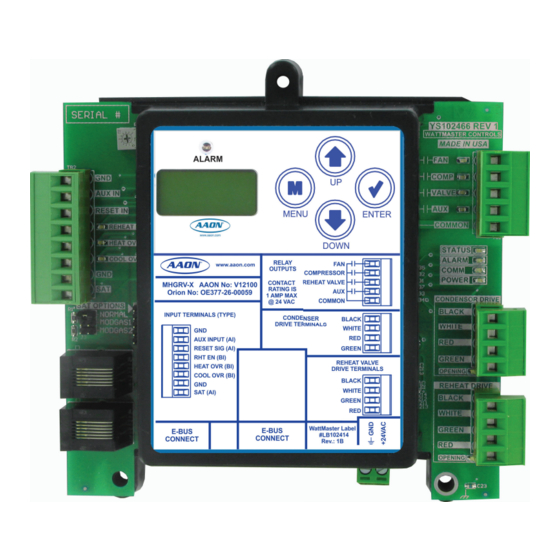
OVERVIEW MHGRV-X Controller General Information Overview Features The V12100 MHGRV-X Controller is designed to control a Modulat- The MHGRV-X provides the following: ing Hot Gas Reheat Valve to maintain a desired Supply Air Tempera- Can be operated as a stand-alone controller or ture setpoint. -
Page 4: Installation & Wiring
MHGRV-X Controller is connected to an that is free from extreme high or low temperatures, moisture, dust, AAON Unit Controller, see Figure 2, page 5. For the stand-alone and dirt. Be careful not to damage the electronic components when wiring diagram, see Figure 3, page 6. -
Page 5: Mhgrv-X Controller To Aaon Unit Controller Wiring
WIRING MHGRV-X to AAON Unit Controller Wiring Communications Wiring When connected to an AAON Unit Controller, the Supply Air Temperature Sensor is attached to the Main Controller. See Figure 2 below. For connection to a VCCX2 or VCB-X Controller, VCCX2 or VCB-... -
Page 6: Mhgrv-X Stand Alone Wiring
WIRING MHGRV-X Stand-Alone Wiring Stand-Alone Wiring In Stand-Alone mode, the MHGRV-X connects to the E-BUS port of the Reheat Expansion Module with an EBC E-BUS cable. See Figure 3 below. See the SAT Wiring Conditions Table and SAT OPTIONS jumper settings in Tables 7 &... -
Page 7: Inputs And Outputs
INPUTS & OUTPUTS Inputs and Outputs I/O Map Binary Inputs REHEAT EN: Reheat Enable Contact The following inputs and outputs are available on the MHGRV-X Controller. See Table 1 below to reference the Input/Output Map. Used only in stand-alone operation. When a call for dehumidifi cation is initiated by another controller, this interlocked 24 VAC wet contact closure is used to enable the MHGRV-X controller. -
Page 8: Operation Overview
OPERATION MODES Operation Modes Initialization the “RESET IN” input. As the voltage increases from 0 to 10 Volts at the “RESET IN” input, the Supply Air Temperature will be reset The MHGRV-X Controller uses on-board LEDs to indicate various towards the Supply Air Reset Temperature Setpoint. This setpoint diagnostic conditions during power-up and operation. -
Page 9: Additional Features
In this mode, the MHGRV-X Controller behaves as an expansion Reheat Coil Flush board for an AAON Unit controller. The controller begins the dehu- To assure positive oil return to the compressor, the Hot Gas Reheat midifi cation process when the AAON Unit controller makes a request Coil will be fl... -
Page 10: Lcd Display Screens
LCD DISPLAY SCREENS Navigation Keys LCD Display Screen & Navigation Navigation Key Key Function Keys MENU Use the MENU key to navigate through the The MHGRV-X Controller allows you to make configuration Main Menu Screens changes, view status, change setpoints, create force modes, and perform diagnostics using the keypad next to the LCD display. - Page 11 LCD DISPLAY SCREENS Main Screens Map and Main MHG REHEAT Screens Main Screens Map Main MHG REHEAT Screens Refer to the following map when navigating through the LCD Main Refer to the following map when navigating through the Main <ENTER> Screens.
- Page 12 LCD DISPLAY SCREENS Status & Alarm Screens Status Screens Refer to the following map when navigating through the Status Screens. From the STATUS Screen, press <ENTER> to scroll ACTIV SP through the screens. XX.X STATUS OR INACTIVE ACTIVE SUPPLY AIR SETPOINT Calculated from SAT setpoint and reset signal.
- Page 13 LCD DISPLAY SCREENS Setpoint & Force Valves Screens Setpoint Screens Force Valves Screens Refer to the following map when navigating through the Set- Refer to the following map when navigating through the Force <ENTER> point Screens. From the SETPOINT Screen, press <ENTER>...
-
Page 14: Troubleshooting
TROUBLESHOOTING Troubleshooting LED Diagnostics Relay LEDs - This green LED will light up to indicate that the relay for the The MHGRV-X Controller is equipped with LEDs that can be used “FAN” output is energized and its Normally Open Contact is closed. to verify operation and perform troubleshooting. -
Page 15: Temperature Sensor Testing
MODGAS Controller (stand-alone mode or when and associated AAON controllers. using a CAV/VAV or MUA Controller) or to AI2 • In communication mode (connected to an AAON and GND on the Main Controller (communicating Unit Controller with modular cable), confi rm that mode). - Page 16 TROUBLESHOOTING Troubleshooting Other Checks Temperature to Resistance/Voltage Chart Temp Temp Resistance Voltage @ 0-3V (SAT OPTIONS Jumper Settings Normal (°F) (°C) (Ohms) Input (VDC) And MODGAS-X) & 0-5V (SAT OPTIONS Jump- 16.7 14014 1.93 er Setting MODGAS) Supply Air Temperature 17.8 13382 1.89...
- Page 17 TROUBLESHOOTING Troubleshooting Temperature to Resistance/Voltage Chart Temperature to Resistance/Voltage Chart Temp Temp Resistance (Ohms) Voltage @ Temp Temp Resistance (Ohms) Voltage @ (°F) (°C) Input (VDC) (°F) (°C) Input (VDC) 37.8 6047 1.927 -23.3 93333 4.620 40.6 5453 1.805 -20.6 80531 4.550 43.3...
-
Page 18: Appendix A - Supply Air Temperature Sensor Guide
This will help prevent thermal gradients from aff ecting the sensor. When communicating with AAON Unit Controllers, the SAT Sensor will be connected to the Main Controller. The exception would be in retrofi t applications with older controllers. See Table 9 on page... -
Page 19: Supply Air Temperature Sensor Wiring Chart And Jumper Settings
APPENDIX A SAT Sensor Wiring Guide & Jumper Settings SAT Wiring Conditions MODGAS-X ONLY MHGRV-X ONLY MODGAS-X & MHGRV-X STAND- Install Supply Air Install Supply Air Install Sensor in MODGAS-X and daisy-chain it ALONE Sensor in MODGAS-X. Sensor in MHGRV-X. to the MHGRV-X. -
Page 20: Mhgrv-X Replacement Of Mhgrv Ii
NOTES Appendix B - MHGRV-X Replacement of MHGRV II Step 4: Set the SAT Options Jumper per Table 8, page 19. Replacing the MHGRV II with the MHGRV-X Step 5: Connect power to the MHGRV-X Controller. COMMUNICATIONS MODE OPERATION The drop-in replacement involves a few easy steps. Refer to Figure 7. Step 1: Disconnect power from the MHGRV-II Controller. -
Page 21: Reheat Expansion Module
APPENDIX C - REHEAT EXPANSION MODULE Features & Dimensions Features Overview The Reheat Expansion Module provides the following: The V42450 Reheat Expansion Module is designed to control one set of reheat valves. Up to (7) Reheat Expansion Modules can be used ... - Page 22 For the wiring diagram to use when the MHGRV-X Controller is The Reheat Expansion Module is provided with a Chevron cut connected to an AAON Unit Controller, see Figure 2, page 5. For plastic snap track mounting base. The snap track is designed to be the stand-alone wiring diagram, see Figure 3, page 6.
- Page 23 APPENDIX C - REHEAT EXPANSION MODULE Wiring Reheat Expansion Module(s) Wiring Reheat Expansion Modules snap into each other at the power and Comm connectors. Up to (7) Reheat Expansion Modules can be used. Apply power to the fi rst Reheat Expansion Module in a series. The last Reheat Expansion Module in a series connects to the MHGRV-X Controller using an EBC E-BUS cable.
- Page 24 In this mode, the MHGRV-X Controller behaves as an expansion to fl ush synchronously instead of independently. board for an AAON Unit controller. See page 8 for detailed opera- tion. Once the Reheat Expansion Module’s Binary Input Compres- Contact AAON Controls Support for assistance in making these sor input is enabled, the valve positions follow the MHGRV-X confi...
- Page 25 APPENDIX C - REHEAT EXPANSION MODULE LED Diagnostics & Troubleshooting LED Diagnostics Communication LED COMM - This amber LED will light up and blink once for every The Reheat Expansion Module is equipped with 4 LEDs that can be good packet received. Packets should be sent once every second, used to verify operation and perform troubleshooting.
- Page 26 APPENDIX C - REHEAT EXPANSION MODULE Troubleshooting Q & A The Reheat Valve should be wired (from top to bottom) BLACK, WHITE, GREEN, RED The following are common questions and their answers: Q: How do I confi rm the expansion module is operating in Q: Is there power to the expansion module? Reheat (Dehumidifi...
- Page 27 NOTES MHGRV-X Field Technical Guide...
- Page 28 AAON Part No.: V16950, Rev. 01M Printed in the USA June 2018 All rights reserved. © 2018 AAON Controls Inc. 8500 NW River Park Dr. Parkville, MO 64152 Phone: 866-918-1100 www.orioncontrols.com Fax (816) 505-1101...
Need help?
Do you have a question about the V12100 MHGRV-X and is the answer not in the manual?
Questions and answers