Table of Contents
Advertisement
Quick Links
Advertisement
Table of Contents

Related Manuals for AAON AA-HB-TGD-01F


Summary of Contents for AAON AA-HB-TGD-01F
- Page 1 HB Controller Technical Guide...
-
Page 2: Table Of Contents
WattMaster Controls, Inc. Form: AA-HB-TGD-01F Copyright 2009 WattMaster Controls, Inc. AAON is a registered trademark of AAON, Inc., Tulsa, OK. 8500 NW River Park Drive · Parkville , MO 64152 ® WattMaster Controls, Inc. assumes no responsibility for errors, or omissions. -
Page 3: Controller Overview
Overview Controller Overview General MHGRV Reset: Modulating Hot-Gas Reheat Signal (0-10VDC) RAB: Return Air Bypass Damper Actuator (by others) The HB Controller is designed to work with a normal 24 VAC Thermostat ECS: (Enthalpy Changeover Switch) and Dehumidistat. Single or Multi-stage Thermostats can be used. When Econo Pos: Economizer Control (by others) a Single-Stage Thermostat is used, an auto-staging feature is built-in for Carbon Dioxide Sensor... -
Page 4: Controller Sequence Of Operation
Sequence of Operations Controller Sequence of Operations Fan Mode Auto Stage-Up Delay Expires or a call for “Y2” is made. When “Y2” is called, Cool Stage 2 will activate after the Cooling Auto Stage-Up The HB Controller supports 2 different Supply Fan confi gurations. It Delay. -
Page 5: Dehumidifi Cation Mode (No Reheat)
Sequence of Operations Controller Sequence of Operations Dehumidifi cation Mode (No Reheat) 2-Stage Cooling with Adjustable Two-Speed or Two-Speed Supply Fan Control On a call for “RH,” Cool Stage 1 is energized, and the Supply Fan runs Note: If the HB Controller is confi gured for 1 stage of Cooling, at low speed. -
Page 6: Sat Lockout Modes
Sequence of Operations Controller Sequence of Operations SAT Lockout Modes Space Temperature Control Sequence When the Space Temperature Sensor is confi gured for control, Cooling and Heating setpoints are used to activate the HVAC Modes of operation. Note: The SAT Lockout Modes only apply if a Supply Air An HVAC Mode Deadband setpoint is used to determine the temperature Temperature Sensor is installed on the HB unit. -
Page 7: Controller Installation & Wiring
Installation & Wiring Controller Installation & Wiring Controller Mounting All wiring is to be in accordance with local and national electrical codes and specifi cations. It is important to mount the controller in a location that is free from Minimum wire size for 24 VAC thermostat wiring should extreme high or low temperatures, moisture, dust, and dirt. - Page 8 Zone Installation & Wiring Zone Controller Installation & Wiring Single Stage T-stat Wiring For HB Unit Single Stage T-stat Wiring For HB Units With 1 Stage Cooling & 1 Stage Heating With 1 Stage Cooling & 1 Stage Heating Single-Stage Thermostat (24VAC) Dehumidistat (24VAC) 1-Cool / 1-Heat...
- Page 9 Installation & Wiring Controller Installation & Wiring Single Stage T-stat Wiring For HB Units With 2 Stage Cooling & 2 Stage Heating Single-Stage Thermostat (24VAC) Dehumidistat (24VAC) 1-Cool / 1-Heat Normally Open HB Controller Terminal Block (GND) 24VAC Power Supply 24VAC to Economizer 24VAC Clogged Filter Indicator...
- Page 10 Zone Installation & Wiring Zone Controller Installation & Wiring Single Stage T-stat Wiring For HB Units With 2 Stage Cooling & 3 Stage Heating Single-Stage Thermostat (24VAC) Dehumidistat (24VAC) 1-Cool / 1-Heat Normally Open HB Controller Terminal Block (GND) 24VAC Power Supply 24VAC to Economizer 24VAC Clogged Filter Indicator...
- Page 11 Installation & Wiring Controller Installation & Wiring Multi-Stage T-stat Wiring For HB Units With 2 Stage Cooling & 2 Stage Heating Multi-Stage Thermostat (24VAC) Dehumidistat (24VAC) 2-Cool / 2-Heat Normally Open W2 W1 HB Controller Terminal Block (GND) 24VAC Power Supply 24VAC to Economizer 24VAC Clogged Filter Indicator...
- Page 12 Zone Installation & Wiring Zone Controller Installation & Wiring Multi-Stage T-stat Wiring For HB Units With 2 Stage Cooling & 3 Stage Heating Multi-Stage Thermostat (24VAC) Dehumidistat (24VAC) 2-Cool / 3-Heat Normally Open W3 W2 W1 HB Controller Terminal Block (GND) 24VAC Power Supply 24VAC to Economizer...
- Page 13 Installation & Wiring Controller Installation & Wiring Optional Jumper Locations For External Control Note: The factory jumpers are located on the bottom two pins for each 3-pin header. For field control of either the Economizer and/or the Return Air EXTERNAL Bypass, move their respective jumpers to the “External”...
-
Page 14: Programming With The Hb Service Tool
Zone Programming Zone Programming with the HB Service Tool Entering Passcodes the DOWN arrow decreases. When the desired letter appears, press the RIGHT ARROW key to advance to the next letter fi eld. Once all four letter fi elds spell the desired passcode, press the ENTER key. The HB Service Tool is used to program setpoints and view the status of the HB controller. -
Page 15: Hb Controller Status & Setpoints
Line #2 displays “YES” if the Outdoor Air Temperature is below the Factory Options Cooling Lockout Temperature Setpoint. OAT Temperature Factory Options should not be accessed without contacting AAON ® or WattMaster. Warning: The Factory Options settings should only be ap-... -
Page 16: Fan Module Status Screens
Zone Programming Zone Programming with the HB Service Tool Program Time Fan Status Fan Status Program Time Fan Off XX:XX:XX Line #2 displays the current Supply Fan Status. If the Supply Fan is on, Line #2 displays the time, in 24-hour (military) format, that the HB line #2 displays either “Fan Low Speed”... -
Page 17: Cooling Module Status Screens
Programming Programming with the HB Service Tool Adjustable Two-Speed Supply Fan Low-Speed Signal Fan Status Low Speed Fan Status Signal Fan Off Line #2 displays the current Supply Fan Status. If the Supply Fan is on, Description Min. Default Max. line #2 displays either “Fan Low Speed”... -
Page 18: Cooling Module Setpoint Screens
Zone Programming Zone Programming with the HB Service Tool High Pressure Switch Low Supply Air Temperature Cutoff Low SAT Cutoff OPEN XXX F Line #2 displays the current status of the High Pressure Switch. It will Description Min. Default Max. only display “CLOSED”... -
Page 19: Heating Module Status Screens
AAON Technical Support. ® The Low Pressure Switch Delay time is a factory setting and should Auto Stage-Up Time not be changed unless authorized to do so by WattMaster or AAON ® Technical Support. Auto Stage Up XXX Sec Low Pressure Switch Safety Delay... -
Page 20: Heating Module Setpoint Screens
Zone Programming Zone Programming with the HB Service Tool Heating Module Setpoint Screens Heating Stage 3 Energized The Heating Module Setpoint Screens are accessed by navigating to the Heating Module and then pressing the ENTER key. The following W3 Active screen will then appear: Status Line #2 displays “YES”... -
Page 21: Economizer Module Status Screens
Line #2 displays the current Supply Air Temperature. Description Min. Default Max. Heat Safety Maximum Count The Heating Safety Maximum Trips is a factory setting and should not be changed unless authorized to do so by WattMaster or AAON ® Technical Support. HB Controller Technical Guide... -
Page 22: Economizer Module Setpoint Screens
Zone Programming Zone Programming with the HB Service Tool Economizer Module Setpoint Screens Outdoor Air Temperature The Economizer Module Setpoint Screens are accessed by navigating to the Economizer Module and then pressing the ENTER key. The fol- lowing screen will then appear: Status Line #2 displays the current Outdoor Air Temperature. -
Page 23: Dehumidify Module Status Screens
Programming Programming with the HB Service Tool CO2 Minimum Position with High-Speed Fan CO2 Level Economizer Opens Above Minimum CO2MinPosHSpdFan Min CO2 XXXX ppm Description Min. Default Max. Description Min. Default Max. Min. CO 0 PPM 900 PPM 2000 PPM Min. -
Page 24: Alarm Module Status Screens
Zone Programming Zone Programming with the HB Service Tool RAB Position Condenser Fan Relay RAB Position Cond Fan Relay XXX% Line #2 displays the current Return Air Bypass damper position. Line #2 displays “ON” if the Condenser Fan Relay is active. Cooling Relay #1 Alarm Module Status Screens Cool 1 Relay... -
Page 25: Force Mode Module Screens
Programming Programming with the HB Service Tool Bad LLT Force Mode Module Screens The Force Mode Module screens are accessed by navigating to the Bad LLT Force Mode Module screen and pressing the ENTER key. After pressing ENTER, the following screen will appear: Force Line #2 displays “YES”... -
Page 26: Force Mode Module Setpoint Screens
Zone Programming Zone Programming with the HB Service Tool Heating Relay #2 Force Economizer Force Force Economizer Heat 2 Relay XXX% Select “YES” to activate Heating Relay #2 and then press ENTER. Adjust the Economizer percentage up or down to position the Econo- mizer where needed and then press the ENTER key. -
Page 27: Factory Options Module Screens
ENTER key. This function requires high-level pass- Adjust the Economizer Maximum Position during High-Speed Supply code access. This passcode can only be obtained by calling AAON or Fan operation when CO levels are above the Maximum CO setpoint WattMaster Technical Support. -
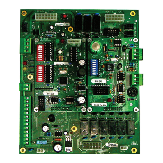
Page 28: Hb Processor Board
Zone Programming Zone Programming with the HB Service Tool HB Processor Board HVAC Mode HB Processor Board Status Screens HVAC Mode Cooling If your HB Controller is equipped with the HB Processor board, you can access the available Status and Setpoint screens by using the program- ming directions that follow. -
Page 29: Hb Processor Setpoint Screens
Programming Programming with the HB Service Tool HB Processor Setpoint Screens Slide Adjust The HB Processor Setpoints Screens are accessed by navigating to the Slide Adjust Setpoints Module screen and then pressing the ENTER key. The fol- lowing screen will appear: Line #2 displays the current Slide Adjust value based on the slide posi- Main Status tion on the Space Temperature Sensor. -
Page 30: Hb Processor Week Schedule Module Screens
Zone Programming Zone Programming with the HB Service Tool Cooling Setback Global Schedule Index Cooling Setback Global Sch Index Using the Adjust keys, adjust up or down for the proper Global Schedule Using the Adjust keys, adjust up or down for the desired Night Setback Index and then press the ENTER key. -
Page 31: Hb Processor Real Time Clock Module Screens
Programming Programming with the HB Service Tool Minute Note: Time must always be entered in 24-Hour format. The example shows how an 8:00 A.M. (08:00 Hrs) start time Minute for Event One on Monday would be set. Using the Adjust keys, adjust up or down to enter the correct Minutes Stop Time for the time of day and then press the ENTER key. -
Page 32: Hot Gas Reheat Controller
Zone Programming Zone Programming with the HB Service Tool Hot Gas Reheat Controller HGR Valve Position Hot Gas Reheat Status Screens HGR Valve Pos If your HB Controller is equipped with the HGR Controller board, XXX.XX you can access the available Status and Setpoint screens by using the programming directions that follow. - Page 33 Programming Programming with the HB Service Tool HGR Controller Reset Count HGR Program Time Program Time Reset Count XX:XX:XX XXXx Line #2 displays the total number of times the HGR Controller has been Line #2 displays the time that the HGR Controller Software was created reset or has had its power cycled.
-
Page 34: Optional Mhgrv Module Settings
Zone MHGRV Module Settings Zone Optional MHGRV Module Settings Supply Air Temperature Example: We want the Discharge Air Temperature Setpoint to increase from 55° F You can set the desired Discharge Air Temperature Setpoint using the when the Reset Input signal is at 0 Volts to 75° F when the Reset Input DIP Switch labeled SETPOINT on the MHGRV Module. - Page 35 MHGRV Module Settings Optional MHGRV Module Settings When a change is made to the DIP Switch settings for either the setpoint MHGRV Valve - Position & Operation or reset, power does not have to be cycled in order for the controller Setpoint Reset Limit Mode of...
-
Page 36: Troubleshooting
Zone Troubleshooting Zone Troubleshooting Using LEDs To Verify Operation HB Controller Fault Condition Operation If the Red LED indicates a Bad Outdoor Air Temperature Sensor, Heating The HB controller is equipped with LEDs that can be used as very Mode will operate, but Cooling Mode will be disabled until the sensor powerful troubleshooting tools. -
Page 37: Appendix
Appendix Appendix The HB controller has many setpoints that are user-adjustable. This Temperature Control Setpoints adjustability allows the installer complete control of all major unit Description Min. Default Max. operating characteristics during the setup and commissioning phase of the HB unit installation. It also gives a service technician the ability Cooling Lockout Temperature 32ºF 40ºF... - Page 38 Zone Appendix Zone Appendix Miscellaneous Control Setpoints Condenser Fan Control Setpoints Description Min. Default Max. Description Min. Default Max. Force Mode Timer 1 Min 60 Min 240 Min Liquid Line Cut Out Temperature 75ºF 85ºF 95ºF Liquid Line Cut In Temperature 95ºF 105ºF 115ºF...
- Page 39 Appendix Appendix Temperature to Resistance/Voltage Chart Temperature to Resistance/Voltage Chart Temp Resistance Voltage @ Temp Resistance Voltage @ (°F) (Ohms) Input (VDC) (°F) (Ohms) Input (VDC) 5453 1.16 93333 2.98 4923 1.09 80531 2.94 4449 1.02 69822 2.89 4030 60552 2.83 3656 52500...
- Page 40 Zone Notes Zone HB Controller Technical Guide...
- Page 41 Notes HB Controller Technical Guide...
-
Page 42: Index
Zone Index Zone Minimum Position with High Speed Fan..22, 27 1 or 2 Stage Cooling Units with Adjustable Two-Speed or Two-Speed Supply Fan Control for Economizer for Economizer..22 Dehumidifi cation..4 Force Mode Setpoint..27 1 Stage Cooling with Adjustable Two-Speed or Two-Speed Minimum Position with Low Speed Fan..22, 27 Supply Fan Control for Dehumidifi... - Page 43 Index Economizer IAQ Control..4 Cooling Relay #1..17, 23 Economizer Module Setpoint Screens..22 for Dehumidify..23 Level Economizer Opens Above Minimum..23 Cooling Relay #1 Force..26 Level Economizer Opens to Economizer for Force Mode..26 Maximum..23 Cooling Relay #2..17, 24 Maximum Position with High Speed Fan..23 for Dehumidify..24 Maximum Position with Low Speed Fan..22 Cooling Relay #2 Force..26...
- Page 44 Zone Index Zone Fan Signal..17, 22, 23 Force Mode Screen for Cooling..17 for Force Mode Module..25 for Dehumidify..23 Force No Limit..27 for Economizer..22 Factory Options..27 for Heating..20 Force Time Limit..25, 27 Fan Signal Force..25 Factory Options..27 for Force Mode..25 for Force Mode..25 Fan Speed Force..25 FRC Schedule..29 for Force Mode..25...
- Page 45 Index HB Processor Real Time Clock Module Screens..31 Heating Stage 2 Energized..19 Day..31 Heating Stage 3 Energized..19 Day of Week..31 Heating Relay #1..20 Hour..31 Heating Relay #1 Force..26 Minute..31 Heating Relay #2..20 Month..31 Heating Relay #2 Force..26 Year..31 Heating Relay #3..20 HB Processor Real Time Clock Module Screens..31 Heating Relay #3 Force..26 HB Processor Setpoint Screens..29...
- Page 46 Zone Index Zone HVAC Mode..28 HB Controller Main Status Screen..15 OAT Changeover to Mechanical Cooling..22 HB Processor Board..28 for Economizer..22 Main Status..15 OAT Cool Lockout..15 HVAC Mode Deadband..30 Main Status..15 HB Processor Setpoint..30 OAT Cooling Lockout..25 for Alarm Module..25 OAT Heat Lockout..15 LED Blink Codes..36 HB Controller Main Status Screen..15 LEDs..36...
- Page 47 Index RAB Position..23 Temperature Control Setpoints..37 for Dehumidify..23 Temperature Sensor - Voltage & Resistance for Type..39 Red LED Blink Codes..36 Thermistor Sensor Testing Instructions..39 Reset Count..29 Troubleshooting..36 HB Processor Board Status..29 Green LED Blink Codes..36 Reset Counts..16 Red LED Blink Codes..36 Main Status..16 Yellow LED Blink Codes..36 Return Air Bypass Force..26...
-
Page 48: Wattmaster Controls, Inc
Ph: (918) 583-2266 • Fax: (918) 583-6094 AAON Part No.: R38220 ® WM Form: AA-HB-TGD-01F Printed in the USA • Copyright 2009 • All Rights Reserved • May 2009 WattMaster Controls, Inc. • 8500 NW River Park Drive • Parkville, MO • 64152...
Need help?
Do you have a question about the AA-HB-TGD-01F and is the answer not in the manual?
Questions and answers