Table of Contents
Advertisement
Advertisement
Table of Contents
Troubleshooting

Subscribe to Our Youtube Channel
Related Manuals for AAON MHGRV-X


Summary of Contents for AAON MHGRV-X
- Page 1 MHGRV-X Controller Field Technical Guide...
- Page 2 AAON assumes no responsibility for errors or omissions in AAON Controls Support: 866-918-1100 this document. It is the intent of AAON to provide accurate and current This document is subject to change without notice. product information. However, in the interest of product...
-
Page 3: Table Of Contents
OVERVIEW ........................5 MHGRV-X General Information..........................5 WIRING ..........................6 Installation and Wiring ............................. 6 MHGRV-X to AAON unit controller Wiring....................... 7 MHGRV-X Stand-Alone Wiring ..........................8 INPUTS AND OUTPUTS ....................9 Inputs and Outputs ..............................9 OPERATION MODES ..................... 10 Operation Modes .............................. - Page 4 FIGURES AND TABLES FIGURES MHGRV-X Dimensions Figure 1: .............................5 MHGRV-X to AAON unit controller Wiring Figure 2: ......................7 MHGRV-X Stand-Alone Wiring Figure 3: ..........................8 LCD Display and Navigation Keys Figure 4: ........................12 MHGRV-X LED Locations and Descriptions Figure 5: .......................17...
-
Page 5: Overview
OVERVIEW MHGRV-X General Information Overview Features The MHGRV-X is designed to control a Modulating Hot Gas The MHGRV-X provides the following: Reheat Valve to maintain a desired Supply Air Temperature • Can be operated as a stand-alone controller or setpoint. The controller can be used as a stand-alone controller communicating with AAON unit controllers. -
Page 6: Wiring
Please carefully read and apply the following information when wiring the Unit Controller, MHGRV-X and any associated The MHGRV-X is housed in a plastic enclosure. It is designed to module. be mounted by using the three mounting holes in the enclosure 1. -
Page 7: Mhgrv-X To Aaon Unit Controller Wiring
WIRING MHGRV-X to AAON Unit Controller Wiring Communications Wiring When connected to an AAON unit controller, the Supply Air Temperature Sensor is attached to the AAON unit controller. For connection to a VCCX2 or VCB-X Controller, VCCX2 or See Figure 2, this page. -
Page 8: Mhgrv-X Stand-Alone Wiring
WIRING MHGRV-X Stand-Alone Wiring Stand-Alone Wiring In Stand-Alone Mode, the MHGRV-X connects to the E-BUS port of the Reheat Expansion Module with an EBC E-BUS cable. See Figure 3, this page. See the SAT Wiring Conditions Table and SAT OPTIONS Jumper Settings in Tables 8 and 9, page 21. -
Page 9: Inputs And Outputs
Inputs and Outputs I/O Map Binary Inputs The following inputs and outputs are available on the MHGRV-X. REHEAT EN: Reheat Enable Contact See Table 2, this page to reference the Input/Output Map. Used only in Stand-Alone operation. When a call for... -
Page 10: Operation Modes
AUX: Two-Position HGR Valve / Reversing Valve The MHGRV-X can be used in two different modes of operation. If configured as standard, this relay will be used to control a These modes behave in a similar manner; the main difference is two-position HGR valve. - Page 11 Communications Operation Reheat Mode Flush In this mode, the MHGRV-X behaves as an expansion board for an If the unit is in dehumidification mode and the valve is below AAON unit controller. The controller begins the dehumidification process when the AAON unit controller makes a request to the 70% for the flush reheat interval timer value, a flush will occur.
-
Page 12: Lcd Screens
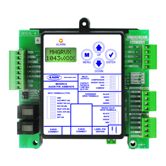
Use this key to adjust setpoints and change ALARM configurations. ENTER Use the ENTER key to navigate through the Main Menu Screen categories. MENU ENTER DOWN Table 3: Navigation Key Functions Figure 4: LCD Display and Navigation Keys MHGRV-X Field Technical Guide... -
Page 13: Main Screens Map And Main Mhg Reheat Screens
Press to go to SETPOINTS Screens. CURRENT SOFTWARE VERSION SETPOINT ADDRESS Press to scroll through SETPOINT Screens. CURRENT BOARD ADDRESS Press to go to FORCE VALVE Screens. FORCE VALVES Press to scroll through FORCE VALVES Screens. MHGRV-X Field Technical Guide... -
Page 14: Status And Alarm Screens
60 seconds. This alarm will be disabled when the sensor is reconnected. COMM T/O ERROR: Communications have been lost with the SA TEMP AAON unit controller. This alarm will disable when communications XX.X resume. SUPPLY AIR TEMPERATURE 40ºF to 150ºF or 5ºC to 65ºC. -
Page 15: Setpoint And Force Valves Screens
This is maximum temperature at which the Supply Air Temperature will reset to. Will display only in Stand-Alone Mode. The Reset SAT Setpoint is set by the LCD Display in Stand-Alone Mode and is set by the AAON unit controller in communicating FORCE mode. -
Page 16: Troubleshooting
This green LED will light up to indicate that the relay for FAN - The MHGRV-X is equipped with LEDs that can be used to the “FAN” output is energized and its Normally Open Contact verify operation and perform troubleshooting. There are LEDs is closed. -
Page 17: Alarms
• Verify that the Supply Air Temperature Sensor is • Check COMM LED on MHGRV-X. connected to the SAT and GND on the MHGRV-X or • Verify 24 VAC power to all interconnected AAON unit MODGAS Controller (Stand-Alone Mode or when controllers. -
Page 18: Other Checks
Note: If the voltage is above 3.3 VDC the sensor or wiring is “open.” If the voltage is less than 0.05 VDC, the sensor or wiring is shorted. Table 6: 0-3V Temperature Sensor - Voltage and Resistance for Type III Sensors MHGRV-X Field Technical Guide... -
Page 19: Table 7: 0-5V Temperature Sensor - Voltage And Resistance For Type Iii Sensors
Note: If the voltage is above 5.08 VDC the sensor or wiring is “open.” If the voltage is less than 0.05 VDC, the sensor or wiring is shorted. Table 7: 0-5V Temperature Sensor - Voltage and Resistance for Type III Sensors MHGRV-X Field Technical Guide... -
Page 20: Appendix A: Sat Sensor
Stand-Alone Mode Sensor In Stand-Alone Mode, the SAT Sensor is connected to the MHGRV-X. If, in Stand-Alone Mode, the MHGRV-X is used in The Supply Air Temperature Sensor should be located in the conjunction with a Stand-Alone MODGAS-X, the SAT sensor ductwork downstream of the unit supply air connection. -
Page 21: Sat Sensor Wiring Guide And Jumper Settings
* For SAT Sensor testing, use Table 6 for Normal jumper setting. jumper setting and use Table 7 for MODGAS jumper setting. SAT should be connected to the AAON unit controller. ** In this situation, also set MODGAS-X SAT Option to Jumper Set- ** For SAT Sensor testing, use Table 6 for Normal jumper setting. -
Page 22: Appendix B: Mhgrv Ii
Refer to Figure 7, this page. is currently installed on the MHGRV II then reinstall Stand-Alone Mode Operation it on the MHGRV-X. If it is currently installed on the main unit controller or on a connected MODGAS, it Disconnect power from the MHGRV II. -
Page 23: Appendix C: Reheat Expansion Module
The Reheat Expansion Module provides the following: one set of reheat valves. • Up to seven Reheat Expansion Modules can be used The Reheat Expansion Module connects to the MHGRV-X via • Each Reheat Expansion Module controls one set of an EBC E-BUS communication cable. -
Page 24: Installation And Wiring
For the wiring diagram to use when the MHGRV-X is connected plastic snap track mounting base. The snap track is designed to to an AAON unit controller, see Figure 2, page 7. For the Stand- be mounted using a ¼” Hex Head Sheet Metal Screw (provided) Alone wiring diagram, see Figure 3, page 8. -
Page 25: Wiring
The last Reheat Expansion Module in a series connects to the Reheat Expansion Modules snap into each other at the power MHGRV-X using an EBC E-BUS cable. and Comm connectors. Up to seven Reheat Expansion Modules See Figure 9, this page for details. -
Page 26: Operation Modes
Reheat Expansion Module follows the same sequence as Reheat Expansion Module’s Binary Input Compressor input is the MHGRV-X, using the same flush reheat interval timer of the enabled, the valve positions follow the MHGRV-X. MHGRV-X. The expansion boards do not flush at the same time. -
Page 27: Led Diagnostics And Troubleshooting
Status code repeatedly blinks the indicated valve Table 11: Reheat Expansion Module ALARM LED ○ position every ten seconds Blink Codes POWER LED COMPRESSOR ENABLE LED STATUS LED COMM LED Figure 10: Reheat Expansion LED Locations and Descriptions MHGRV-X Field Technical Guide... -
Page 28: Troubleshooting
No flush cycles will occur. Q: How can I test if the expansion module will drive the valve? From the MHGRV-X, you can go to the Force Menu and manually drive the expansion module valves open and closed. - Page 29 It should display S/A MODE LOCKED. 3. The MHGRV-X must be configured for EXP VLVS ENABLED in the MHGRV-X Configuration Screens. If this is true, the COMM LED on the MHGRV-X will blink once every second. A: For the MHGRV-X operating with a VCCX2/ VCB-X, the following should be true: 1.
- Page 30 MHGRV-X Technical Guide G086630 · Rev. 01N · 210325 AAON Factory Technical Support: 918-382-6450 techsupport@aaon.com AAON Controls Support: 866-918-1100 Monday through Friday, 7:00 AM to 5:00 PM Central Standard Time Controls Support website: www.aaon.com/controlstechsupport NOTE: Before calling Technical Support, please have the model and serial number of the unit available.
Need help?
Do you have a question about the MHGRV-X and is the answer not in the manual?
Questions and answers