Table of Contents
Advertisement
Quick Links
Advertisement
Table of Contents

Related Manuals for AAON RSMZ


Summary of Contents for AAON RSMZ
- Page 1 Compatible with VCCX/VCCX-IP Series RSMZ Technical Guide ASM02351 Software SS1126...
- Page 2 This manual is available for download from www.aaon.com AAON, Inc. It is the intent of AAON to provide accurate and current product 2425 South Yukon Ave. information. However, in the interest of product improvement, AAON Tulsa, OK 74107-2728 reserves the right to change pricing, specifications, and/or design of its Factory Technical Support Phone: 918-382-6450 product without notice, obligation, or liability.
-
Page 3: Table Of Contents
Input/Output Maps ..............................9 WIRING ................................10 RSMZ Input Wiring - Modules 1, 2, 4, and 5 ......................10 RSMZ Output Wiring - Modules 1, 2, 4, and 5 .......................11 RSMZ Input Wiring - Modules 3 and 6 ........................12 RSMZ Output Wiring - Modules 3 and 6 ....................... - Page 4 FIGURES Figure 1: RSMZ Dimensions .............................7 Figure 2: RSMZ Inputs Wiring - Modules 1, 2, 4, and 5 ..................10 Figure 3: RSMZ Outputs Wiring - Modules 1, 2, 4, and 5 ..................11 Figure 4: RSMZ Inputs Wiring - Modules 3 and 6 ....................12 Figure 5: RSMZ Outputs Wiring - Modules 3 and 6 ....................13...
- Page 5 RSMZ Sensor Status Screens ......................... 24 Table 9: RSMZ Setpoint Status Screens ........................ 24 Table 10: RSMZ Alarms Screens ..........................25 Table 11: RSMZ Faults Screens ..........................25 Table 12: RSMZ Lockouts Screens .......................... 26 Table 13: RSMZ Danfoss Screens ........................... 27 Table 14: Subcool Monitor Main Screens ........................
-
Page 6: General Information
The Refrigerant System Module for VFD Compressors (RSMZ) monitors and controls one refrigeration circuit of the HVAC unit. The RSMZ is used on RZ units and on RN-E units with Danfoss compressors. The module is designed for R410-A refrigerant. The RSMZ is connected to an AAON unit controller. Three or six RSMZ Modules can be connected, depending on the size of the system. -
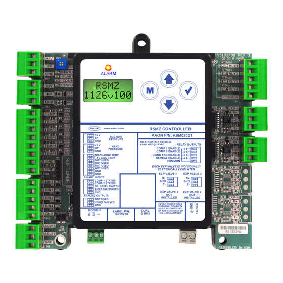
Page 7: Dimensions
24 VAC POWER ONLY WARNING! POLARITY BIN4 MUST BE OBSERVED MODBUS DUAL LABEL P/N: OR THE CONTROLLER E-BUS WILL BE DAMAGED G050220 AOUT1 AOUT2 4.10 Note: All Dimensions are in inches. Note: Depth is 1.50 inches. Figure 1: RSMZ Dimensions RSMZ Technical Guide... -
Page 8: Installation And Wiring
Please carefully read and apply the following information when wiring the unit controller, RSMZ, and any associated module. Correct wiring of the AAON unit controller and its modules is 1. All wiring is to be in accordance with local and national the most important factor in the overall success of the controller electrical codes and specifications. -
Page 9: Inputs And Outputs
INPUTS AND OUTPUTS Input/Output Maps for the RSMZ Module inputs and outputs, Table 2, this page SUBCOOL MONITOR MODULE for Subcool Monitor Module inputs and outputs, Table 3, this page for the Reheat Expansion Module inputs Table 4, this page Analog Inputs and outputs. -
Page 10: Wiring
RSMZ Input Wiring - Modules 1, 2, 4, and 5 RSMZ Input Wiring The RSMZ monitors and controls one refrigeration circuit of the HVAC unit. The RSMZ is used on RZ units and on RN-E units with Danfoss compressors. The module is designed for R410-A refrigerant. -
Page 11: Rsmz Output Wiring - Modules 1, 2, 4, And 5
AOUT2 18-30 Size transformer for correct total load. RSMZ = 18 VA Line Voltage Danfoss VFD Terminals Connect to AAON unit controller and next RSMZ Figure 3: RSMZ Outputs Wiring - Modules 1, 2, 4, and 5 RSMZ Technical Guide... -
Page 12: Rsmz Input Wiring - Modules 3 And 6
OR THE CONTROLLER LABEL P/N: E-BUS WILL BE DAMAGED G050220 AOUT1 AOUT2 18-30 Condenser Fan Size transformer for correct total load. Line Voltage RSMZ = 18 VA Figure 4: RSMZ Inputs Wiring - Modules 3 and 6 RSMZ Technical Guide... -
Page 13: Rsmz Output Wiring - Modules 3 And 6
Note: For RSMZ Module #3, connect to Reheat Expansion Module #1 Comm Terminal Block. For RSMZ Module #6, connect to Reheat Expansion Module #2 Comm Terminal Block. Figure 5: RSMZ Outputs Wiring - Modules 3 and 6 RSMZ Technical Guide... -
Page 14: Reheat Expansion Module
Reheat Expansion Module Wiring Please refer to the MHGRV-X Technical Guide for NOTE: more information. The Reheat Expansion Module connects to the RSMZ Communication Terminal Block. One or two Reheat Expansion Modules are used per system. Observe Polarity! All boards must be wired... -
Page 15: Subcool Monitor Module
R410-A, R22, and R134a refrigerant and can also be configured for the following pressure transducers—250 psi, 500 psi, and 667 psi. The Subcool Monitor Module is connected to the AAON unit controller. One or two Subcool Monitor Modules can be connected, depending on the size of the system. -
Page 16: Sequence Of Operations
Cooling Mode During startup of the Cooling Mode, the RSMZ receives The RSMZ may be configured to operate as any one of six possible communication from the AAON unit controller to indicate Cooling modules in the control system. This configuration automatically Mode which is then used to stage on cooling. -
Page 17: Alarms
These • Parameter 16-90 Alarm Word 1 failures (alarms) will be reported to the AAON unit controller which “DNFSALM1” allows them to be monitored via a BACnet® Building Automation System or with a user interface. -
Page 18: Alarm Faults
The low superheat detection will be ignored for the first two minutes of initial compressor operation. If the superheat drops below 4ºF for two minutes, the compressor signal will be turned off and will be retried after five minutes. RSMZ Technical Guide... -
Page 19: Alarm Lockouts
High Discharge Line Temperature Lockout If a high Discharge Line Temperature fault occurs three times in a two-hour time period, the circuit will be disabled and locked out until the module is reset. RSMZ Technical Guide... -
Page 20: Subcool Monitor Module Operation
The use of the Subcool Monitor Module is optional. Subcooling Sequence The Subcool Monitor Module reads and scales all of its six inputs and calculates the saturated suction and subcooling for each configured circuit. RSMZ Technical Guide... -
Page 21: Lcd Screens
Use this key to adjust setpoints and change configurations. DOWN Use this key to adjust setpoints and change configurations. ENTER Use the ENTER key to navigate through the Main Menu Screen categories. Table 5: Navigation Key Functions RSMZ Technical Guide... -
Page 22: Rsmz Screens Map
LCD SCREENS RSMZ Screens Map RSMZ STATUS SENSOR SETPOINT ALARM ALARM ALARM DANFOSS 1126VXXX MENU MENU STATUS WARNINGS FAULTS LOCKOUTS MENU EBUS COMM MODE SUPPLY SUPPLYSP CONNECT? ° ° +XXXXXX XX.X XX.X YES/NO SOFTWARE STAGE SATURATN EVAPCLSP MB FAIL °... -
Page 23: Rsmz Screen Descriptions
Module 6’s address is 182 C1MIN OFF Compressor 1 minimum off time TONNAGE Unit tonnage C2MIN OFF Compressor 2 minimum off time VFD MAX Maximum speed based on unit tonnage Table 7: RSMZ System Status Screens Table 6: RSMZ Main Screens RSMZ Technical Guide... -
Page 24: Table 8: Rsmz Sensor Status Screens
Discharge temperature reading from input SHEAT SP Superheat setpoint XX.X°F XX.XºF SUCTION Suction pressure reading from input Table 9: RSMZ Setpoint Status Screens XXX PSIG SUPRHEAT Superheat reading from temperature sensor XX.XºF input Table 8: RSMZ Sensor Status Screens RSMZ Technical Guide... -
Page 25: Rsmz Alarms, Faults, And Lockouts
LCD SCREENS RSMZ Alarms, Faults, and Lockouts Lockouts Screens FAULTS SCREENS Screen Text Description If an alarm, fault, or lockout is present, the ALARM LED above ALARM Alarm Faults screens the LCD display lights up red and blinks. The alarms, faults, and... -
Page 26: Table 12: Rsmz Lockouts Screens
LCD SCREENS RSMZ Alarms, Faults, and Lockouts Lockouts Screens If an alarm, fault, or lockout is present, the ALARM LED above the LCD display lights up red and blinks. The alarms, faults, and lockouts scroll automatically from their respective screen when more than one message is present. -
Page 27: Rsmz Danfoss Screens
NO ALARM DNFSALM1 Danfoss 1 alarms. B1-B4 codes B1XX-B4XX DNFSALM2 Danfoss 2 alarms. B1-B4 codes B1XX-B4XX CURRENT Current OA C1 HOURS Compressor 1 hours VFD HRS VFD hours MODEL Danfoss model part number Table 13: RSMZ Danfoss Screens RSMZ Technical Guide... -
Page 28: Subcool Monitor Screens Map
XXX PSIG XXX PSIG XXX PSIG REFRGRNT ADDRESS SATTEMP # SATTEMP # SATTEMP # ° ° ° X (XXX) XXX.X XXX.X XXX.X TRNSDCER TEMP # TEMP # TEMP # ° ° ° PSIG XXX.X XXX.X XXX.X CIRCUITS 1,2,3 RSMZ Technical Guide... -
Page 29: Subcool Monitor Module Screen Descriptions
2 is for the second 3 circuits Table 15: Subcool Monitor Circuit Status Screens Number in parentheses is E-BUS address. Module 1’s address is 169, Module 2’s address is 170. Table 14: Subcool Monitor Main Screens RSMZ Technical Guide... -
Page 30: Table 16: Subcool Monitor Main Screens
COMM This alarm will display if the Subcool Monitor is not TMPSCALE Temperature scaling. Fahrenheit or Celsius TIMEOUT communicating with the AAON unit controller. REFRGRNT Refrigerant type. 410-A, 134a, or R22 Table 16: Subcool Monitor Main Screens TRNSDCER Transducer PSIG. 250, 500, or 667... -
Page 31: Appendix A: Troubleshooting
Every time the module receives a valid E-BUS request COMM - from the AAON unit controller, this LED will blink on and then off, signifying that it received a valid request and responded. This LED will light up to indicate that 24 VAC power POWER - has been applied to the module. -
Page 32: Subcool Monitor Led Diagnostics
Every time the module receives a valid E-BUS request COMM - from the AAON unit controller, this LED will blink on and then off, signifying that it received a valid request and responded. If the software is running, this LED should blink once STATUS - every 10 seconds. -
Page 33: Reheat Expansion Module Led Diagnostics
REHEAT ENABLE LED POWER LED POWER LED REHEAT ENABLE LED COND/REHEAT BLACK WHITE RED/GRN GRN/RED STATUS COMM YS102608 R0 STLZ STATUS 4750 COMM 4750 STATUS LED STATUS COMM COMM LED Figure 11: Reheat Expansion LED Locations and Descriptions RSMZ Technical Guide... -
Page 34: Temperature Sensor Testing
Note: If the voltage is above 5.08 VDC the sensor or wiring is “open.” If the voltage is less than 0.05 VDC, the sensor or wiring is shorted. Table 20: 0-5V Temperature Sensor - Voltage and Resistance for Type III Sensors RSMZ Technical Guide... -
Page 35: Suction Pressure Transducer Testing
RSMZ Module. The VCCX-IP/VCCX2 and 24.49 -4.4 87.16 the RSMZ Module must be powered for this test. Read voltage with a meter set on DC volts. Place the positive lead from the meter 27.80 -2.8 93.39 on the SP1/SP2 terminal located on the RSMZ Module terminal 30.99... -
Page 36: Liquid Line And Head Pressure Transducer
Head Pressure Transducer Testing Use the voltage column to check the Head Pressure Transducer while connected to the RSMZ Module. The module must be powered for this test. Read voltage with a meter set on DC volts. Place the positive lead from the meter on the HP input terminal located on the module. -
Page 37: Appendix B: Danfoss Vfd
0-20 Motor Speed Unit RPM (vs. Hz) blue = user must configure from display yellow = set through communications once communications is established green = default but confirm if not working Table 23: Danfoss VFD Parameter Configurations RSMZ Technical Guide... -
Page 38: Appendix C: System Configuration
In Prism 2’s “Configuration 1 Page”, select the radio button for this configuration will need to be selected. “Check this box for RSMZ modules”, select the radio button for “3 RSMZs” or “6 RSMZs”, and then select the check box for “RSMZ Has Sub-Cooling Module”... - Page 39 Single Condenser for A & B. If there is single condenser other VFD compressor will activate. control for the system then select Single Condenser for the system. Modulating HPC Setpoint Enter the head pressure setpoints used for cooling and dehumidification modes. RSMZ Technical Guide...
- Page 40 PARTS: For replacement parts, please contact your local AAON Representative. 2425 So. Yukon Ave • Tulsa, OK • 74107-2728 Ph: (918) 583-2266 • Fax: (918) 583-6094 AAON P/N: G081900, Rev. B Created in the USA • © July 2024 AAON All Rights Reserved...
Need help?
Do you have a question about the RSMZ and is the answer not in the manual?
Questions and answers