Sign In
Upload
Manuals
Brands
AAON Manuals
Controller
ASM02655
User Manuals: AAON ASM02655 Chiller Controllers
Manuals and User Guides for AAON ASM02655 Chiller Controllers. We have
1
AAON ASM02655 Chiller Controllers manual available for free PDF download: Technical Manual
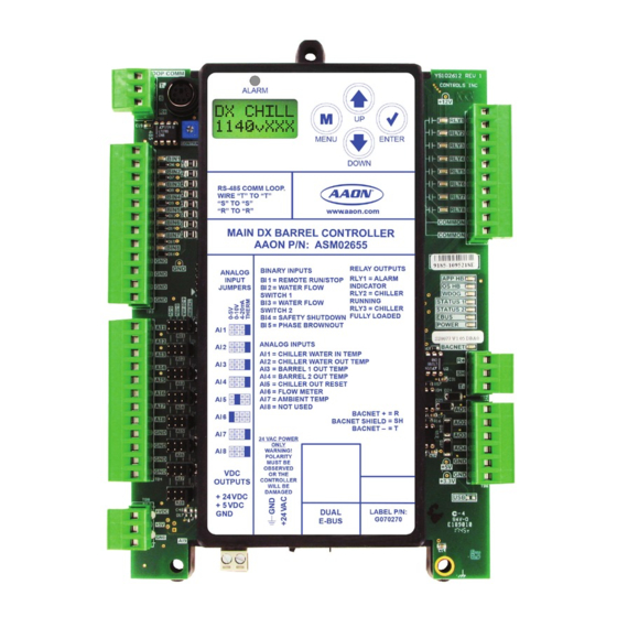
AAON ASM02655 Technical Manual (122 pages)
MAIN DX BARREL CONTROLLER
Brand:
AAON
| Category:
Controller
| Size: 15 MB
Table of Contents
Table of Contents
3
Overview
9
General Information
9
Wiring
10
Important Wiring Considerations
10
Table 1: Main DX Barrel Chiller Controller, Chiller Refrigerant Module and Chiller Pumping Module Electrical and Environmental Requirements
10
Table 2: Evaporative Condenser Module and Vestibule Module Electrical and Environmental Requirements
10
Main DX Barrel Chiller Controller and Refrigerant Module I/O Maps
11
Table 3: Main DX Barrel Chiller Controller Inputs and Outputs
11
Table 4: Chiller Refrigerant Module Inputs and Outputs
11
Vestibule Module and Chiller Pumping Module I/O Maps
12
Table 5: Vestibule Module Inputs and Outputs
12
Table 6: Chiller Pumping Module Inputs and Outputs
12
Evaporative Condenser Module I/O Maps
13
Table 7: Evaporative Condenser Module Inputs and Outputs
13
Main DX Barrel Chiller Controller Input Wiring
14
Figure 1: Main DX Barrel Chiller Controller Input Wiring
14
Main DX Barrel Chiller Controller Output Wiring
15
Figure 2: Main DX Barrel Chiller Controller Output Wiring
15
Chiller Refrigerant Module Input Wiring
16
Figure 3: Chiller Refrigerant Module Input Wiring
16
Chiller Refrigerant Module Output Wiring
17
Figure 4: Chiller Refrigerant Module Output Wiring
17
Chiller Pumping Module Input Wiring
18
Figure 5: Chiller Pumping Module Input Wiring
18
Chiller Pumping Module Output Wiring
19
Figure 6: Chiller Pumping Module Output Wiring
19
Evaporative Condenser Module Input Wiring
20
Figure 7: Evaporative Condenser Module Input Wiring
20
Evaporative Condenser Module Output Wiring
21
Figure 8: Evaporative Condenser Module Output Wiring
21
Vestibule Module Input Wiring
22
Figure 9: Vestibule Module Input Wiring
22
Vestibule Module Output Wiring
23
Figure 10: Vestibule Module Output Wiring
23
Sequence of Operations
24
Main DX Barrel Chiller Controller - Overview
24
Main DX Barrel Chiller Controller - off and Run Modes
25
Main DX Barrel Chiller Controller - Mechanical Chiller Overview
26
Main DX Barrel Chiller Controller - Safety Checks
27
Chiller Refrigeration Module Operation
28
Chiller Refrigeration Module - Safety Checks
29
Vestibule Module - Operation and Safeties
30
Chiller Pumping Module - Waterside Economizer Operation
31
Chiller Pumping Module - Plate Heat Exchanger Operation
32
Chiller Pumping Module - Water Circuit Pumping Operation
33
Trend Logs
34
Table 8: Trend Log Descriptions
34
Trend Log Alarm Bit Strings
35
Table 9: Alarm Group 1 Bit String
35
Table 10: Alarm Group 2 Bit String
35
Table 11: Alarm Group 3 Bit String
35
Table 12: Alarm Group 4 Bit String
35
Table 13: Alarm Group 5 Bit String
35
Table 14: CPM Module Alarms Bit String
35
Table 15: Evaporative Condenser Alarms Bit String
36
Table 16: CPM Relays Bit String
36
Troubleshooting
37
Alarms and Faults
37
Main DX Barrel Chiller Controller LED Diagnostics
38
Main DX Barrel Chiller Controller LED Locations
39
Figure 11: Main DX Barrel Chiller Controller LED Locations
39
Refrigerant Module LED Diagnostics
40
Refrigerant Module LED Locations
41
Figure 12: Refrigerant Module LED Locations
41
Chiller Pumping Module LED Diagnostics
42
Table 17: APP HB LED Blink Codes
42
Chiller Pumping Module LED Locations
43
Figure 13: Chiller Pumping Module LED Locations
43
Evaporative Condenser Module LED Diagnostics and Locations
44
Figure 14: Evaporative Condenser Module Leds
44
Figure 44: Evaporative Condenser Module
44
Vestibule Module LED Diagnostics
45
Figure 15: Vestibule Module Leds
45
Thermistor Sensor Testing
46
Table 18: Temperature and Resistance for Type III 10K Ohm Thermistor Sensors
46
Suction Pressure Transducer Testing
47
Discharge Pressure Transducer Testing
48
Table 20: Discharge Pressure and Voltage Chart for Discharge Pressure Sensors
48
Lcd Screens
49
LCD Display, Navigation Keys and Editing Keys
49
Figure 16: LCD Display Screen and Navigation Keys
49
Table 21: Navigation Key Functions
49
Table 22: Editing Key Functions
49
Lcd Screens
50
Main Screens Map
50
Settings Screens
51
Glycol Screens
52
Status Screens
53
Alarms
54
Table 23: Main DX Barrel Chiller Controller Alarms
54
Rsm - Lcd Screens
55
Main Screens Map
55
RSM Screens
56
Status Menu Screens
57
Sensor Menu Screens
58
Setpoint Status Screens
59
Alarm Screens
60
Table 24: RSM Alarms
60
Table 25: RSM Faults
60
Table 26: RSM Lockouts
61
Chiller Pumping Module - Lcd Screens
62
Main Screens Map
62
Module Screens
63
Module Screens
64
System Status Screens
65
Sensor Status Screens
67
Alarms Screens
68
Table 27: Chiller Pumping Module Alarms
68
Alarms History Screen
69
Setpoint Status Screens
70
Pump Runtime Screens
72
Evaporative Condenser - Lcd Screens
73
Main Screens Map and Module Screens
73
Status Menu Screens
74
Sensor Menu Screens
75
Alarms Screen
76
Table 28: Evaporative Condenser Alarms
76
Setpoint Status Screens
77
Vestibule Module - Lcd Screens
78
Main Screens Map and Module Screens
78
Status, Alarm and Setpoint Screens
79
Table 29: Vestibule Module Alarms
79
Main DX Barrel Chiller Controller - Bacnet
80
MS/TP Connection
80
Figure 17: Bacnet Connection to MS/TP Network
80
Bacnet Analog Inputs
81
Table 30: Bacnet Analog Inputs
81
Bacnet Analog Values
83
Table 31: Bacnet Analog Values
83
Bacnet Binary Inputs
85
Table 32: Bacnet Binary Inputs
85
Bacnet Multi-State Input
93
Table 33: Bacnet Parameter Multi-State Input
93
Touchscreen Interface
94
Overview
94
Figure 18: Panel PC with Touchscreen Interface
94
Start and Logging in Screens
95
Figure 19: Start Screen
95
Figure 20: Help Screen
95
Figure 21: System Overview Screen (View Only)
95
Figure 22: Login Screen
95
Changing the Passcode
96
Figure 23: System Overview Screen (Full Access)
96
Figure 24: New Passcode Screen
96
Figure 25: Manage Users Screen
96
Button and Icon Function
97
Table 34: Navigation Buttons
97
Table 35: Configuration Buttons
97
Table 36: Administrative Icons
97
System Settings
98
Figure 26: System Settings Screen
98
Table 37: System Settings Functions and Buttons
98
Details Screens
99
Figure 27: Chiller Pump Status and Waterside Economizer Status Details Screen
99
Figure 28: Evaporator Condenser Status and Vestibule Status Details Screen
99
Figure 29: RSM Status Details Screen
99
Figure 30: RSM Status and Compressor Staging Status Details Screen
99
Schedules and Overrides
100
Figure 31: Scheduling Screen
100
Figure 32: Time Selection Screen
100
Figure 33: Set Time Screen - Individual Day
100
Setting, Saving and Restoring Holidays and Schedules
101
Figure 34: Holidays Screen
101
Figure 35: Holiday Set Time Screen
101
Setpoints Screens
102
Figure 36: Temperatures Setpoints Screen
102
Figure 37: Staging Delays and Timing Intervals Setpoints Screen
102
Figure 38: Vestibules Setpoints Screen
102
Figure 39: Sensor Calibration Setpoints Screen
102
Configuration Settings Screens
103
Figure 40: System Configuration Main Page
103
Figure 41: Refrigeration Modules Screens
103
Figure 42: Waterside Economizer Settings Screen
103
Figure 43: Boiler Pump Settings Screen
103
Changing Configuration and Setpoint Values
104
Figure 45: Keypad Data Entry Screen
104
Alarms Screen
105
Figure 46: Alarms Logs Screen - Administrative Access
105
Troubleshooting
106
Figure 47: Chiller Rocker Switch Panel (Three Circuit Switches Shown)
106
Prism 2
107
Requirements
107
Controller Status Screen
108
Figure 48: Prism 2 - DX Chiller Main Controller Status Screen
108
Figure 49: Prism 2 - Controller Setpoint Screens
109
Figure 50: Prism 2 - Setpoints - Temperatures
110
Figure 51: Prism 2 - Setpoints - Staging Delays & Timing Intervals
110
Figure 52: Prism 2 - Setpoints - Vestibules #1 and #2
110
Figure 53: Prism 2 - Setpoints - Sensor Calibration
110
Figure 54: Prism 2 - Setpoints - System Configuration
111
Figure 55: Prism 2 - Setpoints - Refrigeration Modules
111
Figure 56: Prism 2 - Setpoints - Waterside Economizer Settings
112
Figure 57: Prism 2 - Setpoints - Building Pump Settings
112
Figure 58: Prism 2 - Setpoints - Evap Condenser Module
113
Changing, Saving, and Restoring Setpoints and Charting
114
Figure 59: Prism 2 - Setpoints - Help Window
114
Figure 60: Prism 2 - Clear Settings Confirmation Window
114
Figure 61: Prism 2 - Charting Selection
114
Figure 62: Prism 2 - DX Barrel Chiller Chart
114
Schedules and Holidays
115
Figure 63: Prism 2 - Charting Selection
115
Figure 64: Prism 2 - Schedules Screen
115
Figure 65: Prism 2 - Yearly Holiday Schedule Screen
115
Schedule Override and Viewing Alarms
116
Figure 66: Prism 2 - Mode Status and Override
116
Figure 67: Prism 2 - Alarms Screen
116
RSM and EVAP Module Alarms Screens
117
Figure 68: Prism 2 - Refrigeration Module Alarms and Reset Screen
117
Figure 69: Prism 2 - EVAP Module Alarms and Reset Screen
117
CPM and Vestibule Alarms and Reset Screens
118
Figure 70: Prism 2 - CPM Alarms and Reset Screen
118
Figure 71: Prism 2 - Vestibule Alarms and Reset Screen
118
Commlink 5 Connection
119
Figure 72: Prism 2 - Commlink 5 Connection
119
IP Module Connection
120
Figure 73: Prism 2 - IP Module Connection
120
USB-Link 2 Connection
121
Figure 74: Prism 2 - USB-Link 2 Connection
121
Advertisement
Advertisement
Related Products
AAON Orion Control Systems ASM01626
AAON ASM02780
AAON ASM01670
AAON ASM02351
AAON AA-HB-TGD-01F
AAON A2L
AAON Orion ASM02221
AAON ASM02293
AAON ASM02869
AAON ASM07265
AAON Categories
Controller
Control Unit
Air Handlers
Heat Pump
Air Conditioner
More AAON Manuals
Login
Sign In
OR
Sign in with Facebook
Sign in with Google
Upload manual
Upload from disk
Upload from URL