Advertisement
Quick Links
A2L Mitigation Controller
Technical Guide
OMRON
SA
G5Q-1
DC12V
VDE
5A30VDC
CHINA
10A250VAC ~
OMRON
SA
G5Q-1
DC12V
VDE
5A30VDC
CHINA
10A250VAC ~
OMRON
SA
G5Q-1
DC12V
VDE
5A30VDC
CHINA
10A250VAC ~
OMRON
SA
G5Q-1
DC12V
VDE
5A30VDC
CHINA
10A250VAC ~
2019WXX
Compatible with
VCCX-454
Series
ASM07563
Advertisement

Related Manuals for AAON A2L


Summary of Contents for AAON A2L
- Page 1 Compatible with VCCX-454 Series A2L Mitigation Controller Technical Guide ASM07563 OMRON G5Q-1 DC12V 5A30VDC CHINA 10A250VAC ~ OMRON G5Q-1 DC12V 5A30VDC CHINA 10A250VAC ~ OMRON G5Q-1 DC12V 5A30VDC CHINA 10A250VAC ~ OMRON G5Q-1 DC12V 5A30VDC CHINA 10A250VAC ~ 2019WXX...
- Page 2 All rights reserved. © October 2024 AAON, Inc. GreenTrol Automation, Inc. Loris, SC. Paragon MicroTrans Series It is the intent of AAON to provide accurate and current product Airflow Monitoring Station is a registered trademark of Paragon Controls, information. However, in the interest of product improvement, AAON Inc., Santa Rosa, CA.
- Page 3 Dimensions ................................6 WIRING ................................7 Important Wiring Considerations ..........................7 Inputs and Outputs ..............................8 Wiring Diagram ............................... 9 OMNIMATE Connector ............................11 ® TROUBLESHOOTING ............................. 12 LED Diagnostics ..............................12 A2L Gas Sensor ..............................13 A2L Mitigation Controller Technical Guide...
- Page 4 A2L Mitigation Controller Components Figure 1: ........................6 Analog Input Pin Diagram Figure 2: ............................8 A2L Mitigation Controller Wiring Diagram - Air Flow Figure 3: ................... 9 A2L Mitigation Controller Wiring Diagram - Cabinet Figure 4: ................... 9 A2L Mitigation Controller Wiring - Connected to VCCX-454 Figure 5: ................
- Page 5 If it does not light up, verify the 24 VAC is connected to the The A2L Controller will remain in the alarm state for five minutes controller, the wiring connections are tight, and they are wired for after the sensor is cleared before returning to normal operation.
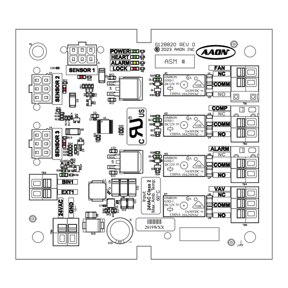
- Page 6 OMRON G5Q-1 DC12V 5A30VDC CHINA 10A250VAC ~ 4.40 OMRON G5Q-1 DC12V 5A30VDC CHINA 10A250VAC ~ OMRON G5Q-1 DC12V 5A30VDC CHINA 10A250VAC ~ 2019WXX Note: All Dimensions are in inches. Figure 1: A2L Mitigation Controller Components A2L Mitigation Controller Technical Guide...
- Page 7 *VA Load is dependent on sensor configuration. Table 1: Voltage and Environment Requirements Wiring The A2L Mitigation Controller and expansion modules must be connected to a 24 VAC power source of the proper size for the calculated VA load requirements. All transformer sizing should be...
- Page 8 Alarm - Normal condition held closed Signal Out VAV - Normal condition held open COMM Common Table 2: Analog Inputs Wiring VAV - Normal condition held closed Table 4: Relay Inputs Wiring Figure 2: Analog Input Pin Diagram A2L Mitigation Controller Technical Guide...
- Page 9 24 VAC NOTE: When two A2L Mitigation Controllers are used, wire the compressor relay in series. Figure 3: A2L Mitigation Controller Wiring Diagram - Air Flow NOTE: The Sensor Bypass Plug is Sensor 1 only used if a sensor is not installed.
- Page 10 VCCX-454 5A30VDC CHINA 10A250VAC ~ Fan Proof of Flow Signal Common OMRON G5Q-1 DC12V Signal 5A30VDC CHINA 10A250VAC ~ Field 2019WXX Connection 24 VAC Figure 5: A2L Mitigation Controller Wiring - Connected to VCCX-454 A2L Mitigation Controller Technical Guide...
- Page 11 WIRING OMNIMATE Connector ® Release Buttons Figure 6: OMNIMATE Connector Instructions A2L Mitigation Controller Technical Guide...
- Page 12 A2L Mitigation Controller LEDs The three red Sensor LEDs indicates the attached sensor detects a fault or the sensor is not connected. The A2L Mitigation Controller is equipped with LEDs that can be Binary LEDs used to verify operation and perform troubleshooting.
- Page 13 TROUBLESHOOTING A2L Gas Sensor Wiring The A2L gas sensor is wired as shown on Figure 8, this page. LED Lights When the sensor is powered up, an LED will indicate the sensor status. While the sensor is mounted, the LED will backlight the sensor and be visible by reflection from the mounting service.
- Page 14 PARTS: For replacement parts, please contact your local AAON Representative. 2425 So. Yukon Ave • Tulsa, OK • 74107-2728 Ph: (918) 583-2266 • Fax: (918) 583-6094 Rev. E Created in the USA • © October 2024 AAON All Rights Reserved...
Need help?
Do you have a question about the A2L and is the answer not in the manual?
Questions and answers