Table of Contents
Advertisement
Quick Links
Advertisement
Table of Contents

Related Manuals for AAON Orion Control Systems MiniLink PD 5


Summary of Contents for AAON Orion Control Systems MiniLink PD 5
- Page 1 MiniLink PD 5 Technical Guide...
- Page 2 AAON P/N: G042660, Rev. 01C 2425 South Yukon Ave. Copyright October 2020 AAON, Inc. Tulsa, OK 74107-2728 AAON, Inc. assumes no responsibility for errors or omissions. www.aaon.com This document is subject to change without notice. Factory Technical Support Phone: 918-382-6450 Windows 10 is a registered trademark of Microsoft Corporation.
-
Page 3: Table Of Contents
TABLE OF CONTENTS OVERVIEW ........................4 Features ..............................4 Dimensions .............................. 5 Environmental Requirements ........................5 Mounting ..............................5 CONFIGURATION ......................6 Address Dipswitch Setting ........................6 Network Loop & Local Loop Baud Rate Selection ................... 7 APPENDIX A - TERMINAL WIRING ...................8 MiniLink PD 5 Terminal Wiring ......................... -
Page 4: Overview
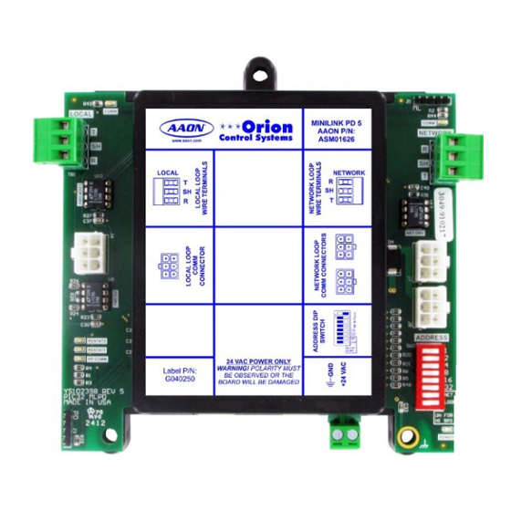
OVERVIEW Overview & Features Overview Features The MiniLink PD 5 is an RS-485 communications device that MiniLink PD 5 utilizes token passing communication ar- is used to integrate multiple local RS-485 communication loops chitecture. The MiniLink PD 5 is designed to serve as the local into an RS-485 network communications system. -
Page 5: Dimensions
OVERVIEW Dimensions & Mounting Environmental Requirements Mounting The MiniLink PD 5 needs to be installed in an environment that The MiniLink PD 5 is housed in a plastic enclosure. It is designed can maintain a temperature range between -30°F and 150°F and to be mounted by using the 3 mounting holes in the enclosure a humidity range between 0% and 95% RH (non-condensing). -
Page 6: Configuration
CONFIGURATION Address Dipswitch Setting Address Dipswitch Setting NOTE: The Power To The MiniLink Must Be Removed And Reconnected After Changing The Address Switch MINILINK PD 5 Settings In Order For Any Changes To Take Effect. Address 1 Address 13 ADDRESS LOOP LOOP LOOP... -
Page 7: Network Loop & Local Loop Baud Rate Selection
CONFIGURATION Network Loop & Local Loop Baud Rate Settings Network Loop & Local Loop Baud Rate Settings NETWORK BAUD SPEED LOOP SWITCH 7 NOTE: The MiniLink PD 5 Is Factory Set 115,200 HIGH* to Low Speed. 19,200 LOW** NOTE: The Power To The MiniLink Must Be Removed And Reconnected In Order LOCAL BAUD... -
Page 8: Appendix A - Terminal Wiring
APPENDIX A - TERMINAL WIRING MiniLink PD 5 Terminal Wiring NOTE: All Communication Wiring Must Be Plenum-rated, Minimum 18-gauge, 2-conductor, Twisted Pair With Shield Wire. AAON Can CAUTION: CAUTION: Supply Communication Wire That Meets This Specification And Is Disconnect All Communication Loop Wiring Disconnect All Communication Loop Wiring Color Coded For The Network Or Local Loop. -
Page 9: Networked Single Loop Wiring With Vav/Zone Bacnet
APPENDIX A - TERMINAL WIRING Networked Single RS-485 Loop Wiring 1002 .1uF .1uF .1uF .1uF .1uF .1uF .1uF .1uF 1002 .1uF .1uF .1uF .1uF .1uF .1uF 1002 .1uF .1uF .1uF .1uF SERIAL # .1uF PD DRV LOOP DRV 1002 1002 Figure 5: MiniLink PD 5 RS-485 Networked Single Loop Wiring MiniLink PD 5 Technical Guide... -
Page 10: Networked Multiple Loop Wiring With Vav/Zone Bacnet
APPENDIX A - TERMINAL WIRING Networked Multiple RS-485 Loop Wiring 1002 .1uF .1uF .1uF .1uF .1uF .1uF .1uF .1uF 1002 .1uF .1uF .1uF .1uF .1uF .1uF 1002 .1uF .1uF .1uF .1uF SERIAL # SERIAL # .1uF .1uF PD DRV PD DRV LOOP DRV 1002 1002... -
Page 11: Appendix B - Modular Wiring
APPENDIX B - MODULAR WIRING Power/Comm Board Wiring NOTE: The MiniLink PD 5 will connect to a Power/Comm Board Only If Power/Comm Cables are Used to Daisy-Chain Between VAV/Zone A Power/Comm Cable Can Be Used Controllers. To Connect With The MiniLink PD 5’s Local Loop Connection Instead Of Using 2-Conductor Twisted Pair With Shield Cable. -
Page 12: Minilink Pd 5 Modular Wiring
Polarity Is Maintained To Each Device On The Transformer Circuit. WARNING: If Polarity Is Not Maintained, Severe Damage To The Devices May Result. AAON Recommends 24 VAC Transformer Using A Separate Transformer For Each Device In Order Size For 6 VA Max. Load To Eliminate The Potential For Damaging Devices Due To Incorrect Polarity. -
Page 13: Networked Multiple Loop Modular System Wiring
APPENDIX B - MODULAR WIRING Networked Multiple RS-485 Loop Modular System Wiring SERIAL # SERIAL # .1uF .1uF PD DRV PD DRV LOOP DRV 1002 1002 LOOP DRV 1002 1002 Figure 9: MiniLink PD 5 RS-485 Networked Multiple Loop Modular System Wiring MiniLink PD 5 Technical Guide... - Page 14 PARTS: For replacement parts please contact your local AAON Representative. 2425 South Yukon Ave • Tulsa, OK • 74107-2728 Ph: (918) 583-2266 • Fax: (918) 583-6094 AAON P/N: G042660, Rev. 01C Printed in the USA • © October 2020 AAON • All Rights Reserved ®...
Need help?
Do you have a question about the Orion Control Systems MiniLink PD 5 and is the answer not in the manual?
Questions and answers