Sign In
Upload
Download
Table of Contents
Contents
Add to my manuals
Delete from my manuals
Share
URL of this page:
HTML Link:
Bookmark this page
Add
Manual will be automatically added to "My Manuals"
Print this page
×
Bookmark added
×
Added to my manuals
Manuals
Brands
AAON Manuals
Controller
R90800
Technical manual
AAON R90800 Technical Manual
Vcm-x,tulsa, full digital module
Hide thumbs
1
Table Of Contents
2
3
4
5
6
7
8
9
10
11
12
13
14
15
16
page
of
16
Go
/
16
Contents
Table of Contents
Troubleshooting
Bookmarks
Table of Contents
Table of Contents
Overview
Installation and Wiring
Environmental Requirements
Mounting
Power Supply and Communications
Important Wiring Considerations
VCM-X Modular E-BUS Controller to Full Digital Module Wiring
Start-Up and Commissioning
General
Unit Confi Gurations
Modes of Operation
Digital Stage 1 / Digital Stage 2
Off Mode
Cooling Mode
Heat Pump Heating Mode (Air to Air)
Dehumidifi Cation Mode
Defrost Mode
Staging Delays
Troubleshooting
Using Leds to Verify Operation
LED Diagnostics
Suction Pressure Transducer Testing
Appendix
VCM-X Controller to Full Digital Module Wiring
Advertisement
Quick Links
1
Overview
2
Installation and Wiring
3
Start-Up and Commissioning
4
Unit Confi Gurations
5
General
6
Troubleshooting
7
Led Diagnostics
8
VCM-X Controller to Full Digital Module Wiring
Download this manual
Factory Packaged Controls
Tulsa
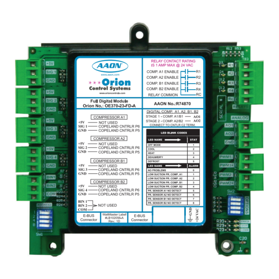
Full Digital Module
Technical Guide
Table of
Contents
Previous
Page
Next
Page
1
2
3
4
5
Advertisement
Table of Contents
Need help?
Do you have a question about the R90800 and is the answer not in the manual?
Ask a question
Questions and answers
Related Manuals for AAON R90800
Controller AAON RSMV-HP Technical Manual
(32 pages)
Controller AAON RSMD Technical Manual
(40 pages)
Controller AAON RSMZ Technical Manual
Compatible with vccx/vccx-ip series (40 pages)
Controller AAON V07150 Technical Manual
Vcm-x,tulsa, full digital module (16 pages)
Controller AAON SS1079 Technical Manual
Vcc-x controller operator interface sd (98 pages)
Controller AAON AA-HB-TGD-01F Technical Manual
(48 pages)
Controller AAON V12100 MHGRV-X Field Technical Manual
Designed to control a modulating hot gas reheat valve to maintain a desired supply air temperature setpoint. (28 pages)
Controller AAON A2L Technical Manual
Mitigation controller (14 pages)
Controller AAON VCCX2 Technical Manual
(95 pages)
Controller AAON VCCX-IP Technical Manual
(96 pages)
Controller AAON Orion VCCX2 Technical Manual
(140 pages)
Controller AAON Orion VCCX2 Technical Manual
(116 pages)
Controller AAON Orion VCCX2 Technical Manual
Latest main controller updatable and customizable (134 pages)
Controller AAON Pioneer Gold 3.0 Technical Manual
(112 pages)
Controller AAON Orion BACnet General Controller Technical Manual
(18 pages)
Controller AAON Pioneer Gold Technical Manual
(94 pages)
This manual is also suitable for:
R74870
R69190
R82930
R69180
R74860
R90230
...
Show all
V07150
Table of Contents
Save PDF
Print
Rename the bookmark
Delete bookmark?
Delete from my manuals?
Login
Sign In
OR
Sign in with Facebook
Sign in with Google
Upload manual
Upload from disk
Upload from URL


Need help?
Do you have a question about the R90800 and is the answer not in the manual?
Questions and answers