
Related Manuals for AAON VCCX-454


Summary of Contents for AAON VCCX-454
- Page 1 Compatible with VCCX-454 Series VCCX-454 Controller Technical Guide ASM07503 Software SS1186...
- Page 2 All rights reserved. © JULY 2024 AAON, Inc. GreenTrol Automation, Inc. Loris, SC. Paragon MicroTrans Series It is the intent of AAON to provide accurate and current product Airflow Monitoring Station is a registered trademark of Paragon Controls, information. However, in the interest of product improvement, AAON Inc., Santa Rosa, CA.
-
Page 3: Table Of Contents
Airflow Station ............................... 27 START-UP AND COMMISSIONING ....................... 28 Powering Up and Configuration ..........................28 INPUTS AND OUTPUTS ..........................29 VCCX-454 Controller Inputs/Outputs Maps ......................29 EM1 Inputs/Outputs Maps ............................ 30 A2L Mitigation Controller Inputs/Outputs Maps ..................... 31 BD-3PI Inputs/Outputs Maps ..........................32 VCCX-454 Controller Inputs/Outputs Descriptions .................... - Page 4 BACnet Connection to MS/TP or IP Network ......................81 Analog Inputs ................................ 82 Analog Values ............................... 91 Binary Inputs ................................. 97 Enumerated Fields .............................. 101 Bitfields ................................102 BACnet Protocol Implementation Conformance Statement - VCCX-454 ............104 VCCX-454 Controller Technical Guide...
- Page 5 Typical Networked Single Loop System Layout Figure 29: ....................72 Typical Networked Multiple Loop System Layout Figure 30: ....................73 LCD Display and Navigation Keys Figure 31: ........................74 VCCX-454 BACnet Connection to MS/TP or IP Network Figure 32: ................81 VCCX-454 Controller Technical Guide...
- Page 6 TABLE OF TABLES TABLES Voltage and Environment Requirements Table 1: ........................8 VCCX-454 Controller Analog and Binary Inputs and Outputs Table 2: ................29 EM1 Expansion Module Analog and Binary Inputs and Outputs Table 6: ..............30 Analog Inputs Wiring Table 10: ...............................31...
-
Page 7: Introduction
It also has an on-board BACnet ports for connection • Emergency shutdown input (smoke detector/firestat or to an MS/TP or IP network. The VCCX-454 contains a 2 x 8 LCD other shutdown conditions) character display and four buttons that allow for status and alarm •... -
Page 8: Safety
See Table 1, this page • Be sure all wiring connections are properly inserted and for a list of the required operating conditions for the VCCX-454 tightened into the terminal blocks. Do not allow wire Controller and associated expansion modules. -
Page 9: A2L Leak Detection Sequences
The A2L Leak Detect alarm will stay active on the NOTE: VCCX-454 even if the condition is cleared. It can only If the unit is commanded unoccupied at any time while be manually cleared by power cycling the VCCX-454 or by using the keypad and display on the VCCX-454. -
Page 10: Overview
Application assumes unit has return air to allow for unoccupied operations with outdoor air damper closed. Dehumidification mode utilizes the outdoor air dewpoint and resets the coil temperature based off the supply air dewpoint. VCCX-454 Controller Technical Guide... -
Page 11: Part Number Cross Reference
Standard Room Sensor - Plain or W/ Override ASM02227 / ASM01638 Standard Room Sensor - with Setpoint Adjust or Setpoint Adjust and ASM01642 / ASM01643 Override Strap-On Temperature Sensor Kit ASM01624 Suction Pressure Transducer ASM02222 USB-Link 2 Kit ASM02244 VCCX-454 Controller Technical Guide... -
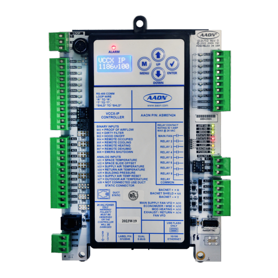
Page 12: Vccx-454 Controller Components
EXHAUST/RETURN = AO4 MUST BE FAN VFD OBSERVED OR THE CONTROLLER WILL BE USB FLASH DAMAGED ONLY USB port 10/100 LABEL P/N DUAL ETHERNET G127590 E-BUS Auxiliary Power Out Ethernet port Figure 1: VCCX-454 Controller Components VCCX-454 Controller Technical Guide... -
Page 13: Dimensions
FAN VFD OBSERVED OR THE CONTROLLER WILL BE USB FLASH DAMAGED ONLY DUAL 10/100 LABEL P/N ETHERNET E-BUS G127590 4.10 Note: All Dimensions are in inches. 0.70 Note: Depth is 1.50 inches. Figure 2: VCCX-454 Controller Dimensions VCCX-454 Controller Technical Guide... -
Page 14: A2L Mitigation Controller
10A250VAC ~ OMRON G5Q-1 DC12V 5A30VDC CHINA 10A250VAC ~ 4.40 OMRON G5Q-1 DC12V 5A30VDC CHINA 10A250VAC ~ OMRON G5Q-1 DC12V 5A30VDC CHINA 10A250VAC ~ 2019WXX Note: All Dimensions are in inches. Figure 3: A2L Mitigation Controller Components VCCX-454 Controller Technical Guide... -
Page 15: Bd-3Pi Third Party Interface Module
DIMENSIONS BD-3PI Third Party Interface Module ASM07771 2019WXX Input: 24VAC Class 2 Max. Amb. Temp: 60 C Note: All Dimensions are in inches. Figure 4: BD-3PI Third Party Interface Dimensions VCCX-454 Controller Technical Guide... -
Page 16: Vcc-X Em1 Expansion Module
OR THE CONTROLLER CONNECT G040660 CONNECT WILL BE DAMAGED 1002 OPTIONS 1002 0.20 ADDRESS .01uF 0.62 2.05 4.10 Note: All Dimensions are in inches. Note: Depth is 1.50 inches. Figure 5: VCC-X EM1 Expansion Module Dimensions VCCX-454 Controller Technical Guide... -
Page 17: 12 Relay E-Bus Module
R211 RELAY R213 TB10 EXPANSION BOARD YS102324 REV 2 24VAC 1002 0.20 POWER COMM .1uF 0.71 2.05 4.10 Note: All Dimensions are in inches. Note: Depth is 1.50 inches. Figure 6: 12 Relay E-BUS Module Dimensions VCCX-454 Controller Technical Guide... -
Page 18: Wiring
Connect FRP Tubing to High Pressure Port (bottom tube) and route to Static Pressure Pickup Probe located in unit discharge. Plug into VCCX2 Leave port marked “LO” open to atmosphere. Controller’s Duct Static Port Figure 7: VCCX-454 Controller Input Wiring VCCX-454 Controller Technical Guide... -
Page 19: Figure 8: Vccx-454 Controller Output Wiring
OBSERVED OR THE CONTROLLER WILL BE USB FLASH DAMAGED ONLY 10/100 LABEL P/N DUAL G127590 E-BUS ETHERNET Size transformer for correct total load. VCCX-IP Controller = 15VA Waterside Economizer Valve Figure 8: VCCX-454 Controller Output Wiring VCCX-454 Controller Technical Guide... -
Page 20: A2L Mitigation Controller
24V Control Voltage OMRON G5Q-1 DC12V Alarm Enable 5A30VDC CHINA 10A250VAC ~ 24V Control Voltage OMRON Jumper G5Q-1 DC12V Heating Disable 5A30VDC CHINA 10A250VAC ~ 2019WXX 24 VAC Figure 10: A2L Mitigation Controller Wiring Diagram - Cabinet VCCX-454 Controller Technical Guide... -
Page 21: Bd-3Pi Third Party Interface Module
The BD-3PI Third Party Interface Module maintains supervisory and • The BD-EPI uses the Omimate ® Connector. See Figure thermostat operation in conjunction with the VCCX-454 Controller. for connect/disconnect instructions. 12, page 22 It is configured through Prism 2 and has the following modes: • Supervisory Mode •... -
Page 22: Omnimate ® Connector
WIRING OMNIMATE Connector ® Release Buttons Figure 12: OMNIMATE Connector Instructions VCCX-454 Controller Technical Guide... -
Page 23: Em1 Expansion Module
WIRING EM1 Expansion Module The EM1 Expansion Module connects to the VCCX-454 Controller It is very important to be certain that all wiring with an E-BUS cable and adds an additional five analog inputs, five WARNING: is correct as shown in the wiring diagram analog outputs, three binary inputs, and five configurable relay below. -
Page 24: Figure 15: Em1 Exhaust Duct Static Pressure And Economizer Actuator Feedback Wiring
Belimo Actuator wiring shown. Consult factory for other manufacturer wiring instructions. (by others) Connect to Connect to Set jumper to 0-10 V Controller Expansion Module(s) (when used) Figure 15: EM1 Exhaust Duct Static Pressure and Economizer Actuator Feedback Wiring VCCX-454 Controller Technical Guide... -
Page 25: Figure 16: Em1 Expansion Module Output Wiring
DIRECT FIRE ALARM SIGNAL 24 VAC POWER ONLY WARNING! POLARITY MUST BE OBSERVED E-BUS LABEL P/N: E-BUS OR THE CONTROLLER CONNECT G040660 CONNECT WILL BE DAMAGED (for Return Plenum Pressure Control Applications) Figure 16: EM1 Expansion Module Output Wiring VCCX-454 Controller Technical Guide... -
Page 26: 12 Relay E-Bus Expansion Module
12 Relay E-BUS Expansion Module E-BUS cable connects to Controller E-BUS cable connects to the next Expansion Board Figure 17: 12 Relay E-BUS Expansion Module Wiring VCCX-454 Controller Technical Guide... -
Page 27: Airflow Station
MicroTransEQ series of MODBUS RTU transmitters are compatible with the VCCX-454 Controller. No other series of transmitters will work for this application. Contact AAON Controls for information on other airflow station options. -
Page 28: Start-Up And Commissioning
Configuring the Controller The next step is configuring the controller for specific requirements. In order to configure the VCCX-454 Controller, use an operator interface. This controller is configured only through Prism II Use Prism II to configure units with RM-454-D, NOTE: RM-454-V and RM-454-Z modules. -
Page 29: Inputs And Outputs
Table 5: VCCX-454 Controller Relay Outputs A2L Cabinet Leak Detect The following E-BUS sensors and modules are available to connect Not Used to the VCCX-454 Controller via E-BUS ports or E-BUS Expansion Emergency Shutdown Modules: Table 3: VCCX-454 Controller Binary Inputs •... -
Page 30: Em1 Inputs/Outputs Maps
Motorized Exhaust Damper Table 8: EM1 Expansion Module Analog Outputs RELAY OUTPUTS (24 VAC) OUTPUT NAME RLY1 Configurable Relay RLY2 Configurable Relay RLY3 Configurable Relay RLY4 Configurable Relay RLY5 Configurable Relay Table 9: EM1 Expansion Module Relay Outputs VCCX-454 Controller Technical Guide... -
Page 31: A2L Mitigation Controller Inputs/Outputs Maps
Alarm - Normal condition held closed Signal Out VAV - Normal condition held open COMM Common Table 10: Analog Inputs Wiring VAV - Normal condition held closed Table 12: Relay Inputs Wiring Figure 19: Analog Input Pin Diagram VCCX-454 Controller Technical Guide... -
Page 32: Bd-3Pi Inputs/Outputs Maps
BD-3PI Inputs/Outputs Maps BINARY INPUTS NAME OCC/G COOLING/Y HEATING/W DEHUM/DH DISABLE HW/O SPARE/E Table 13: BD-3PI Binary Inputs Wiring ANALOG INPUTS NAME SAT RESET SAF SPEED RAF SPEED ECON POS Table 14: BD-3PI Analog Inputs Wiring VCCX-454 Controller Technical Guide... -
Page 33: Vccx-454 Controller Inputs/Outputs Descriptions
AI5 - Building Static Pressure Sensor Input BI3 - Hood On/Off Input This sensor is only required if configuring the VCCX-454 Controller When this wet contact input closes (hood on), the VCCX-454 for building pressure control. Building pressure control can be Controller switches from indoor air control to outdoor air control. - Page 34 If only dry contacts are provided, the contact closure is not be recognized. All binary inputs are optional. This means the VCCX-454 For reverse acting building pressure control using the NOTE: Controller must be configured to recognize these input outdoor air damper or supply fan VFD, the VCCX- signals.
-
Page 35: Bd-3Pi Inputs/Outputs Descriptions
BD-3PI Inputs/Outputs Descriptions OCC/G SAT RESET When this wet contact input closes, it forces the VCCX-454 This input only functions in DDC mode. If a remote supply air Controller into the Occupied Mode. When the OCC/G signal is temperature reset signal is configured as the reset source, this input... -
Page 36: Vcc-X Em1 Expansion Module Inputs/Outputs Descriptions
12 Relay E-BUS Expansion Module control. This static pressure reading is used to control the output These relays are configurable by the user. signal (AO4 on the VCCX-454 Controller) supplied to the exhaust fan VFD. Binary Inputs BI1 - Return/Exhaust Proof of Flow... -
Page 37: User Configurable Relay Outputs
If configured, this relay will energize anytime the space sensor push-button override is active. Alarm Active If configured, this relay will energize anytime a VCCX-454 alarm is active. A1 Comp Run Status Will enable when the RSM A1 compressor activates. -
Page 38: Sequence Of Operations
The VCCX-454 Controller can utilize several methods for determining the Occupied Mode of Operation. These are as follows: The VCCX-454 Controller can be configured to have various HVAC • Forced schedule source options that will determine the mode of operation (Heating, •... - Page 39 When the remote forced occupied signal is removed, the controller will revert to the Unoccupied Mode of operation, or if an internal VCCX-454 schedule is also being used, it will revert to the current scheduled mode. Setting the internal week schedule to “0” will cause the controller to only look for the remote forced occupied signal for occupied/ unoccupied commands.
-
Page 40: Modes Of Operation
Cooling with the Refrigerant System Modules the active Supply Air Cooling Setpoint. The modulating cooling On units with digital or VFD compressors, the VCCX-454 Controller proportional window is used to determine the signal to the chilled will utilize one or more refrigeration modules. Units with only water valve and is user adjustable. - Page 41 Direct Fire Heating The VCCX-454 supports the use of a direct fire heater. The VCCX- In the Heating Mode, as the supply air temperature falls below the 454 sends and receives signals from a direct fire heater controller active Supply Air Heating Setpoint, the heating will begin to stage made by another manufacturer.
- Page 42 Damage to the unit could occur since the outdoor air damper remains default of 0%, the controller will not initiate this protection sequence. closed in the Unoccupied Mode. This operation works during emergency shutdown. VCCX-454 Controller Technical Guide...
- Page 43 Dehumidification Operation on Chilled Water Units If the unit is equipped with a MHGRV-X, during Dehumidification it For chilled water units, the VCCX-454 Controller will open the will modulate the reheat valve to maintain the supply air temperature chilled water valve to a fixed 100% position to provide full moisture at the active Supply Air Temperature Setpoint.
- Page 44 Heat Pump Standard Defrost Operation If using the VCCX-454 Controller with an installed defrost coil When the SAT rises above the SAT setpoint the MHGRV will temperature switch, a defrost cycle is available.
- Page 45 SEQUENCE OF OPERATIONS Modes of Operation Heat Pump Adaptive Defrost Operation When the VCCX-454 Controller is configured for Morning Warm- The adaptive defrost operation adjusts the time interval (adaptive Up and switches to the Occupied Mode of Operation (not Override defrost timer) in between Defrost Mode cycles.
- Page 46 If utilizing the Title 24 economizer option, an economizer feedback signal (0-10 VDC) can be wired into the EM1 Expansion Module for status monitoring. Several Title 24 alarm conditions can also be displayed. VCCX-454 Controller Technical Guide...
- Page 47 The digital sensors each need to be configured with unique addresses (#1 -10) and have an LCD display for this operation. In A remote contact control option can be configured on the VCCX-454 this arrangement, only the sensor at address #1 can utilize the slide Controller to initiate the HVAC Modes of operation.
- Page 48 Outdoor Air Temperature Sensor connected directly to the established by the configured Low and High Supply Air Temperature VCCX-454 Controller) will be used as the temperature that locks out Setpoints. compressors during heat pump heating mode. See the PREHEAT-X Module Technical Guide for more details.
- Page 49 In order to maintain a constant cubic feet per minute through the unless close observation reveals that the supply fan or bypass damper supply air ducts on a mixed air constant air unit, the VCCX-454 can is hunting and not maintaining a stable pressure reading.
- Page 50 Outdoor Air Damper damper will open to 30% and wait 30 seconds to turn on the return If this option is configured, the VCCX-454 will use the user- fans. This is done to prevent any damage to either the return or adjustable economizer/outdoor air damper output signal (AO2 exhaust damper assemblies.
- Page 51 This is accomplished by simply configuring Night Setback sends the VCCX-454 a 0-10 VDC signal on analog input 6 based on Temperature Setpoints (anything other than the default 30ºF) on a its exhaust demand.
- Page 52 Space Heating High and a Space Heating Low If there is no demand, the VCCX-454 switches to Vent Mode. If the Reset Source Setpoint. outdoor air temperature is greater than the Hood On HVAC Cooling...
- Page 53 Cooling Head Pressure Setpoint, the second stage of head pressure control will be disabled. In this operation, if night setback operation will be initiated by a Space Sensor connected to the VCCX-454 Controller, then the Sump Heater Operation night setback Cooling and Heating offsets will be applied to the...
- Page 54 The sump and condenser valves are open. drain enable relay can be disabled in one of two ways: 1. Cycle power to the VCCX-454 when the sump temp is For waterside economizer bypass wiring, please see NOTE: above the Sump Drain Enable Setpoint or the RM-454-D Technical Guide.
-
Page 55: Alarms
The A2L Leak Detect alarm will stay active • Exhaust Airflow Sensor Alarm on the VCCX-454 even if the condition is cleared. It can only be • Supply Airflow Sensor Alarm manually cleared by power cycling the VCCX-454 or by using the •... - Page 56 A 24 VAC wet contact input is available to be used when a normally closed smoke Detector, Firestat, or other shutdown condition occurs. If this contact opens, it will initiate shutdown of the VCCX-454 and will generate an alarm condition. If an Occupied relay is configured, it will remain energized.
-
Page 57: Figure 22: Prism 2 Direct Fire Alarms Screen
Expansion Boards If the controller is configured to have any of the below expansion boards (Modules), but the VCCX-454 controller does not detect that board, then the applicable alarm will occur. If the board is properly detected after the unit has alarmed, the alarm will be cleared. -
Page 58: Figure 23: Prism 2 Compressor Alarms Screen
In the Prism 2 Alarm Menu, Click OK on Compressor Alarms and the following detail screen will appear: Refer to the individual RSM Technical Guides for more details. Figure 24: Prism 2 EVAP Module Alarms Screen Figure 23: Prism 2 Compressor Alarms Screen VCCX-454 Controller Technical Guide... -
Page 59: Trend Logs
AlrmGrp5 (Bit String)* Refrigeration Module Alarms Table 17: RM-454-Z Module Trend Log Binary Inputs Status Bin IN (Bit String)* Relays Status of VCCX-454 and EM1 Main Rly (Bit String)* Relays Status of 12 Relay Expansion Exp Rly (Bit String)* Module * Bit String and Enumeration Value information and interpretation is explained in the paragraphs and tables at the end of this section. -
Page 60: Table 18: Rm-454-V/Rm-454-D Module Trend Logs
A2 Discharge Temperature 1DisChg2 (ºF) Relay Status 1Relay1 (Bit String)* * Bit String and Enumerated Value information and interpretation is explained in the paragraphs and tables at the end of this section. Table 18: RM-454-V/RM-454-D Module Trend Logs VCCX-454 Controller Technical Guide... -
Page 61: Table 20: Rm-454-Z Module Comp Status Trend Log
1 = Timer Exceeded 5RSMAlrms Compressor2_NotRunning 6RSMAlrms Table 22: RM-454-Z Module VFD Status Trend Log LowSuperheat HighDischargeTemperature DMQ_NoDetect ModBusSlaveCommTO LowSuctionComp2Off 1024 TripHighDiscPSI_Comp2 2048 HighSuperheat 4096 HighEvapTemp 8192 EmergencyShutdown Table 21: RM-454-Z Module RSM Alarm Trend Log VCCX-454 Controller Technical Guide... - Page 62 The tables on the following pages provide the bits, values and to decode the VCCX-454 trend log items that are indicated as being descriptions for the various points on the VCCX-454 Controller bit string values.
-
Page 63: Table 23: Vccx-454 Trend Log Bit Strings
VCCX-454 Relay #7 Configurable VCCX-454 Relay #8 Configurable EM1 Relay #1 Configurable EM1 Relay #2 Configurable 1024 EM1 Relay #3 Configurable 2048 EM1 Relay #4 Configurable 4096 EM1 Relay #5 Configurable Table 23: VCCX-454 Trend Log Bit Strings VCCX-454 Controller Technical Guide... -
Page 64: Table 24: Vccx-454 Trend Log Bit Strings (Continued)
Defrost Mode Relay 1 Active RM-454-V/RM- Relay 2 Active 454-D Relay 3 Active 1Relay1 Relay 4 Active 2Relay2 Relay 5 Active 3Relay3 Unloader 1 Active 4Relay4 Unloader 2 Active Table 24: VCCX-454 Trend Log Bit Strings (continued) VCCX-454 Controller Technical Guide... -
Page 65: Troubleshooting
Flash drives formatted as NTFS, exFAT, or any other file system will not work. Multiple hex files can be on the USB drive – the VCCX-454 will only update if the software number is the same (SS1186) and the hex file is a higher version than what is currently on the VCCX-454. -
Page 66: Led Diagnostics
COMM - every 10 seconds. And finally, if one of the outputs is in Force Mode, from the VCCX-454 Controller, this LED blinks on and then off, the LED blinks three times every 10 seconds. indicating it received a valid request and responded. -
Page 67: Figure 25: Vccx-454 Controller Led Locations
OBSERVED OR THE CONTROLLER WILL BE USB FLASH DAMAGED ONLY 10/100 LABEL P/N DUAL ETHERNET G127590 E-BUS Figure 25: VCCX-454 Controller LED Locations RELAY OUTPUT TERMINALS YS102482 REV1 4992 1002 10uF www.aaon.com STATIC PRESSURE 1002 EXHAUST DUCT 1002 10uF STATIC... -
Page 68: Figure 27: A2L Controller Led Locations
10A250VAC ~ OMRON G5Q-1 DC12V 5A30VDC CHINA 10A250VAC ~ 2019WXX Figure 27: A2L Controller LED Locations OPERATION LEDs ASM07771 2019WXX Input: 24VAC Class 2 Max. Amb. Temp: 60 C BIN LEDs Figure 28: BD-3PI LED Locations VCCX-454 Controller Technical Guide... -
Page 69: Temperature Sensor Testing
1.246 12191 2.746 57.2 3015 1.159 20.6 11906 2.717 2743 1.077 21.1 11652 2.691 62.7 2502 1.001 21.7 11379 2.661 65.6 2288 0.931 Table 25: 0-5V Temperature Sensor - Voltage and Resistance for Type III Sensors VCCX-454 Controller Technical Guide... -
Page 70: Pressure Sensor Testing
GND terminal and the “+” (plus) lead on the right side of the Place the “-” (minus) lead on terminal labeled GND and the “+” resistor labeled R85. Be sure to replace the jumper after checking. lead on terminal AI5 on the VCCX-454 Controller. DUCT STATIC PRESSURE SENSOR BUILDING PRESSURE SENSOR... -
Page 71: Appendix A: System Configuration
Prism II connected on the communications loop. Networked System For a networked single loop system, a range of one to 59 VCCX-454 Controllers sharing information, connect the controllers together using AAON communications wire or 18-gauge, two-conductor, twisted pair with shield wire (Belden #82760 or equivalent). -
Page 72: Networked System Single Loop Layout
APPENDIX A: SYSTEM CONFIGURATION Networked System Single Loop Layout LT1785 Figure 29: Typical Networked Single Loop System Layout VCCX-454 Controller Technical Guide... -
Page 73: Networked System Multiple Loop Layouts
APPENDIX A: SYSTEM CONFIGURATION Networked System Multiple Loop Layouts LT1785 Figure 30: Typical Networked Multiple Loop System Layout VCCX-454 Controller Technical Guide... -
Page 74: Appendix B: Lcd Screens
The <MENU> key cancels editing when in Edit Mode. The screen you were editing will return to its original value and the underscore will disappear. A second press of the <MENU> key will return you to the Main Menu. Table 29: Editing Key Functions VCCX-454 Controller Technical Guide... -
Page 75: Main Screens Map
Edit No XX Speed 0.0 % XXX.XXX XXX.XXX XXX.XXX XXX.XXX CO2Level X ppm Gateway Gateway DHCP Edit No XXX.XXX XXX.XXX XXX.XXX XXX.XXX Ethernet Ethernet Mac ADDR Mac ADDR XX-XX-XX XX-XX-XX XX-XX-XX XX-XX-XX DHCP DHCP Disabled Enabled VCCX-454 Controller Technical Guide... -
Page 76: Screen Descriptions
Used to override relay and analog outputs. Override Air Balance screens that can be used by air Balance balance to set min and max fan speeds. Factory This screen is for AAON factory use only. Testing Table 30: Main Screens VCCX-454 Controller Technical Guide... -
Page 77: Table 32: Settings Screens - Bac Type Mstp
Address. This address cannot be modified. XX-XX-XX The Ethernet Mac Address XX-XX-XX DHCP With DHCP disabled, most entries can be manually configured. Enabling DHCP disables the manual Disabled configuration of IP settings. Table 33: Settings Screens - BAC Type IP VCCX-454 Controller Technical Guide... -
Page 78: Table 34: Status Screens
RA Temp Return air temperature. XX.X° OA Temp Outdoor air temperature. XX.X° OA RH Outdoor air humidity. 0.00% - 100%. X.X % CO2Level Carbon dioxide level. 0.00 ppm to 5000 ppm. X ppm Table 34: Status Screens VCCX-454 Controller Technical Guide... -
Page 79: Table 35: Alarms Screens
ECONO Title 24 Economizer alarms FAILURE RET FAN Return/Exhaust fan proving alarm FAILURE DIR FIRE Direct fire heat alarm ALARM Fan Array Controller alarm ALARM Table 35: Alarms Screens VCCX-454 Controller Technical Guide... -
Page 80: Table 36: Output Override Screens
Maximum fan voltage. 0.0 to 10.0 VDC. Press the 10.0 VDC <UP> and <DOWN> buttons to change the value. RELAY #1 VCCX-454 controller relays 1-8. Press the <UP> Default is 10.0. AUTO button to change the value. Default is AUTO. -
Page 81: Appendix C: Bacnet Guide
1. All wiring to be in accordance with local and national electrical codes and specifications. 2. All communication wiring to be 18-gauge minimum, two-conductor, twisted pair with shield. Use Belden #82760 or equivalent. Figure 32: VCCX-454 BACnet Connection to MS/TP or IP Network VCCX-454 Controller Technical Guide... -
Page 82: Analog Inputs
Return Bypass Position AI: 33 Current Signal to the Return Air Bypass Damper if using Return Air Bypass Modulating Cooling Position AI: 34 Current percentage of the Modulating Chilled Water Signal Objects labeled AI are read-only. VCCX-454 Controller Technical Guide... - Page 83 AI: 67 Current Compressor A2 Discharge Temperature A1 Leaving Water Temp AI: 68 Current A1 Leaving Water Temperature for WSHP B1 Compressor Signal AI: 69 Current Compressor B1 Modulating Cooling Signal Objects labeled AI are read-only. VCCX-454 Controller Technical Guide...
- Page 84 Current Compressor C1 Suction Line Temperature C2 Suction Line Temperature AI: 105 Current Compressor C2 Suction Line Temperature C1 Condenser Suction Temp AI: 106 Current Compressor C1 Suction Line Temperature (Heat (Heat Pump) Pump) Objects labeled AI are read-only. VCCX-454 Controller Technical Guide...
- Page 85 Current position of Condenser D1 Expansion Valve Valve Position Condenser D2 Expansion AI: 140 Current position of Condenser D2 Expansion Valve Valve Position D1 Discharge Temperature AI: 141 Current Compressor D1 Discharge Temperature Objects labeled AI are read-only. VCCX-454 Controller Technical Guide...
- Page 86 Current RM-454-Z 2 Warnings See RM-454-Z Warnings Bits on page 102. RM-454-Z 2 Comp VFD AI: 176 Current RM-454-Z 2 Comp VFD Alarms 1 See RM-454-Z Alarms 1 Bits on page 103 Alarms 1 Objects labeled AI are read-only. VCCX-454 Controller Technical Guide...
- Page 87 Current RM-454-Z 4 Warnings See RM-454-Z Warnings Bits on page 102 RM-454-Z 4 Comp VFD AI: 209 Current RM-454-Z 4 Comp VFD Alarms 1 See RM-454-Z Alarms 1 Bits on page 103 Alarms 1 Objects labeled AI are read-only. VCCX-454 Controller Technical Guide...
- Page 88 Current RM-454-Z 6 Suction pressure 2 RM-454-Z 6 Suction Line AI: 241 Current RM-454-Z 6 Suction Line Temperature 2 Temp 2 RM-454-Z 6 Saturation Temp AI: 242 Current RM-454-Z 6 Saturation Temperature 2 Objects labeled AI are read-only. VCCX-454 Controller Technical Guide...
- Page 89 Difference between supply air temperature and mixed air temperature on units with Direct Fire Heat. Calculated Heat Rise AI: 282 The heat rise limit determined by how open the Outside Damper is. Objects labeled AI are read-only. VCCX-454 Controller Technical Guide...
- Page 90 Space Dew Point AI: 285 Current value of the calculated Space Dew Point. Return Dew Point AI: 286 Current value of the calculated Return Dew Point. Objects labeled AI are read-only. VCCX-454 Controller Technical Guide...
-
Page 91: Analog Values
Warm-Up Mode activates if the Return Target Temperature) Air is below this temperature by one degree Objects labeled AV are read/write. The only sensor values that can be written to are AV points 72, 73, and 76 through 79. VCCX-454 Controller Technical Guide... - Page 92 Temperature at which the Low Ambient Relay activates in -30°F (-34.4°C) 70°F (21.1°C) Setpoint the Occupied or Unoccupied Mode Objects labeled AV are read/write. The only sensor values that can be written to are AV points 72, 73, and 76 through 79. VCCX-454 Controller Technical Guide...
- Page 93 Min Damper Position is proportionally reset between the configured Min Damper Position and the Max Position in High CO2. Objects labeled AV are read/write. The only sensor values that can be written to are AV points 72, 73, and 76 through 79. VCCX-454 Controller Technical Guide...
- Page 94 Dehumidification. During Coil Temp Reset, this is the lowest Space RH value that corresponds to the High Coil Temp Setpoint. If the VCCX-454 is configured for indoor dewpoint control, this point displays Dew Point instead of Humidity. Indoor Humidity Setpoint High...
- Page 95 This must be an infrequent event, so the default is 15 minutes. Objects labeled AV are read/write. The only sensor values that can be written to are AV points 72, 73, and 76 through 79. VCCX-454 Controller Technical Guide...
- Page 96 BMS wants them disabled. Supply Air Dew Point Setpoint AV: 99 When the VCCX-454 is configured for DX-DOAS control it modulates the compressors to try to maintain the Supply Air Dew Point Setpoint during dehumidification mode. Objects labeled AV are read/write. The only sensor values that can be written to are AV points 72, 73, and 76 through 79.
-
Page 97: Binary Inputs
BI: 36 Occurs when the Controlling Sensor Temperature rises above the Cooling Mode Enable Setpoint plus the Control Mode High Alarm Offset. Applies only to Space or Return Air Temperature controlled units. Objects labeled BI are read-only. VCCX-454 Controller Technical Guide... - Page 98 BI: 76 Status of MHGRV Controller A1 Compressor Enable BI: 77 Current Status of Enable Signal to Compressor A1 A2 Compressor Enable BI: 78 Current Status of Enable Signal to Compressor A2 Objects labeled BI are read-only. VCCX-454 Controller Technical Guide...
- Page 99 Emergency Shutdown Input on Module D Refrigerant Module 4 Relay 1 BI: 120 Current Status of Compressor 1 Enable Relay Refrigerant Module 4 Relay 2 BI: 121 Current Status of Compressor 2 Enable Relay Objects labeled BI are read-only. VCCX-454 Controller Technical Guide...
- Page 100 Indicates the max calculated heat rise is limiting the Supply Air Setpoint to a lower value. Fan Array Failure BI: 150 Indicates a Fan Array Failure A2L Leak Detect BI: 151 Indicates an A2L Airstream or Cabinet Leak Objects labeled BI are read-only. VCCX-454 Controller Technical Guide...
-
Page 101: Enumerated Fields
VCCX HVAC MODE STATUS = ENUMERATED ITEM ENUM Vent Mode Cooling Mode Heating Mode Vent RH Mode Cooling RH Mode Heating RH Mode Warm Up Mode Purge Mode Defrost Mode Cool Down Mode Table 40: VCCX Mode Status = Enumerated VCCX-454 Controller Technical Guide... -
Page 102: Bitfields
0=Voltage Okay; 16384 Emergency Shutdown Exceeded 1=Voltage Exceeded Table 42: RM-454-Z Faults Status Bit Strings Torque 16384 0=Torque Okay; Exceeded 1=Torque Exceeded Timer 32768 0=Timer Okay; Exceeded 1=Timer Exceeded Table 44: RM-454-Z Drive Status Bit Strings VCCX-454 Controller Technical Guide... -
Page 103: Table 45: Rm-454-Z Module Vfd1 Alarm Trend Log
24 V Supply Low Mains Failure 1.8V Supply Low 1024 Brake Resistor 2048 Brake IGBT 4096 Option Change 8192 Drive Initialized 16384 Safe Stop 32768 Mech brake low Table 46: RM-454-Z Module VFD2 Alarm Trend Log VCCX-454 Controller Technical Guide... -
Page 104: Bacnet Protocol Implementation Conformance Statement - Vccx-454
APPENDIX C: BACNET GUIDE BACnet Protocol Implementation Conformance Statement - VCCX-454 BACnet® Protocol Implementation Conformance Statement Date: March 2024 Vendor: AAON Product: VCCX-454 Product Model Number: ASM07503 Product Version: FW 1.09 Product Description: HVAC Unit Controller BACnet Protocol Revision: Revision 15 (ANSI/ASHRAE Standard 135-2019) BACnet®... - Page 105 PARTS: For replacement parts, please contact your local AAON Representative. 2425 So. Yukon Ave • Tulsa, OK • 74107-2728 Ph: (918) 583-2266 • Fax: (918) 583-6094 Rev. B Created in the USA • © July 2024 AAON All Rights Reserved...
Need help?
Do you have a question about the VCCX-454 and is the answer not in the manual?
Questions and answers