Table of Contents
Advertisement
Quick Links
Advertisement
Table of Contents

Related Manuals for TESTO 6740


Summary of Contents for TESTO 6740
- Page 1 6740 Instruction manual...
-
Page 2: Preface
Preface Dear Testo Customer Congratulations for choosing a Testo product. We hope that you will enjoy many years of using the product and that it will help you in your work. If problems should occur which you cannot rectify yourself, please consult our service department or your dealer. -
Page 3: General Information
General information 3 General information This Instruction manual contains important information about the features and use of the product. Please read this document through carefully and familiarise yourself with the operation of the product before putting it to use. Keep the Instruction manual to hand so that you can refer to it when necessary. -
Page 4: Table Of Contents
Contents Contents Preface ..............2 General information ..........3 Contents..............4 1. Basic safety information ..........5 2. Intended use ............6 3. Product description ..........7 System components ..........7 Operating elements ..........7 Settings ..............8 Current output intervals ..........8 4. Initial operation ............9 Mechanical assembly ..........9 Electric connection ..........11 Analog output / Limit signal outputs ......14... -
Page 5: Basic Safety Information
Please adhere to the steps described. For safety reasons, please only use spare parts from Testo. Any additional work should only be carried out by authorised trained personnel. Otherwise Testo does not accept responsibility for the functioning of the instrument following maintenance and for the validity of approvals. Dispose of carefully: Once its service life has come to an end, return the instrument to us and we will dispose of it. -
Page 6: Intended Use
2. Intended use The instrument is intended for use in the following applications: The testo 6740 instrument is a pressure dew point transmitter for measuring trace humidity. It is used in the following areas: - Monitoring trace humidity in compressed air systems and gas networks (e.g. -
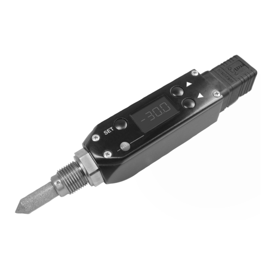
Page 7: Product Description
The instruments with the article numbers 0555.6743 and 0555.6744 have a keypad and a display to input and read off settings (See 5. Menu guide, p. 16). All of the instruments of Type testo 6740 can be parameterised with the aid of the 0554.3305 scaling adapter. -
Page 8: Settings
3. Product description 3.3 Settings 3.3 Settings The parameters in the instrument are assigned the following values in the factory (default values): Parameter Atmospheric dew point Relative humidity Temperature Absolute humidity Pressure dew point Unit °Ctp °Ftp °CtA °FtA %rF, %rh, %Hr °C °F mg/m... -
Page 9: Initial Operation
Without measurement chamber - Process temperatures 0 to 50°C and cooling coil - It is possible to attach sensor directly in process - No quick assembly/dismantling of testo 6740 required and flow on sensor is sufficient (1l/min) With measurement chamber - Process temperatures 0 to 50°C... - Page 10 10 - 30 s, in order to blow out any dirt deposits 2 Remove measurement chamber from compressed air push-in quick connection. 3 Screw in process connection (G½) of testo 6741 / 6743 transmitter into thread of measurement chamber. 4 Snap push-in quick connection of measurement chamber in push-in quick connection of the cooling coil.
-
Page 11: Electric Connection
4. Initial operation 4.2 Electric connection 4.2 Electric connection Standard plug We recommend an 8 wire cable with a tightly braided screen and a core cross-section of 0.2 to 0.5mm 1 Loosen and remove screw at the back of the ... - Page 12 4. Initial operation 4.2 Electric connection 0554.3302 plug (with 2 switch outputs) We recommend an 8 wire cable with a tightly braided screen, wire cross-section 0.2 to 0.8mm 1 Loosen and remove screw at the back of the ...
- Page 13 4. Initial operation 4.2 Electric connection 6 Push plug socket and plug board into the plug housing (pay attention to alignment) and close lid. 7 Screw on cable positioning device. 8 Attach plug to transmitter and screw into place ...
-
Page 14: Analog Output / Limit Signal Outputs
4. Initial operation 4.3 Analog output / Limit signal outputs 4.3 Analog output / Limit signal outputs Standard plug/ 0554.3302 plug Both plug variations have a 4 to 20mA analog output available in two-wire technology. x x , , y y c c o o n n n n e e c c t t i i o o n n : : Connection x Terminal 1 y Terminal 2... - Page 15 4. Initial operation 4.3 Analog output / Limit signal outputs Limit signal outputs with 0554.3302 plug Two floating contacts (NO contact) are available. H H Y Y S S t t , default setting: 2K H H Y Y S S t t LS = On US = On Switch contact closed...
-
Page 16: Menu Guide (0555.6743 / 0555.6744 Only)
16 5. Menu guide 5. Menu guide (0555.6743 / 0555.6744 only) Display from (see 1,2,11, 13 Display mode Reading and unit alternately / Reading continuously (see CodE Unit ProG Set unit (Unit) Display: Min. value (Lo) Enter code Pressure dew point °Ctp/ 4 digit password, default °Ftp, atm. - Page 17 5. Menu guide Return to UNIT ALAr Set lower switching Reference value > -60°tpd Carry out reset (rES) point (LS) (rEF) nor = No reset = +1 = +1 rS = Reset (return to = Next digit = Next digit default setting)) Select using Set upper switching...
- Page 18 5. Menu guide ( 0555.6743 only) supplement available from versioin June 2007 on. For older versions an update of the firmware is necessary Return to UNIT Carry out reset (rES) Reference value > -60°tpd Display value P (rEF) nor = No reset rS = Reset (return to = +1 default setting))
-
Page 19: Adjustment On Site
>-30 °C tpd (else loss of precision). 1 Expose reference measuring instrument and testo 6740 to identical, constant conditions and await adjustment time. 2 Measure reference value and compare with testo 6740 reading. - Page 20 () of the 2-pressure adjustment device (), the sensor of the testo 6743 is exposed to two different pressure levels. In front of the switchover cock () of the 2-pressure adjustment device () is a sintered filter () which prevents dirt particles, rust and oil from...
- Page 21 6. Adjustment on site 21 Installation 1 Screw instrument testo 6743 (G1/2"process connection) into the adjustment chamber (). 2 Connect 2-pressure adjustment device () to the compressed air pipe with the compressed air fast coupling (diameter 7.2). The permitted operating pressure is 3-16 bar.
- Page 22 () and re-install for continuous operation. Limits of the adjustment chamber In order to avoid false adjustments, the adjustment described above is only accepted by testo 6743 if The temperature during the adjustment process remains constant, i. e. the temperature difference is less than 0.5 Kelvin: (I T1-T2 I <...
-
Page 23: Care And Maintenance
7. Care and Maintenance 7. Care and Maintenance Filter, measurement chamber, cooling coil If process conditions are oily or dusty, the stainless steel sintered filter should be cleaned and also the measurement chamber and cooling coil should be cleaned if used. Unscrew/remove filter, measurement chamber and cooling coil, purge with compressed air or place in an ultrasonic bath. -
Page 24: Troubleshooting
Unit - S-Lo or S-Hi Menu If the fault cannot be repaired by following the suggestions given in the above table, please contact your local distributor or Testo`s Customer service department. For contact data, see back of this document or web page www.testo.com/service-contact... -
Page 25: Technical Data
Storage/transport temperature -20 to +80°C Protection classIP65 (with plug attached and cable connected) Rotatability 350° (display alignment) Humidity sensor Testo humidity sensor with logged trace humidity-adjustment at -40°Ctp/6bar Temperature sensor Sensor protection Stainless steel sintered cap Pressure resistance -1bar to +50bar Measurement chamber 0554.3303: max. -
Page 26: Uncertainty Pressure Dewpoint Temperature
9. Technical data 9.3 Uncertainty pressure dewpoint temperature 9.3 Uncertainty pressure dewpoint temperature... -
Page 27: Accessories / Spare Parts
ISO calibration certificate for pressure dew point (-40° to 0°Ctp at 6bar), free choice of points 0520 0116 ISO calibration certificate for pressure dew point at -10°Ctp and -40°Ctp 0520 0136 External display testo 54-2AC, 2 relay outputs (to 300VAC, 3A), 230VAC 5400 7553 PTFE hose with compressed air connections, 2m, max. 9bar 0699 2824/4... - Page 28 0970 6740 en 08 en-GB...
Need help?
Do you have a question about the 6740 and is the answer not in the manual?
Questions and answers