Table of Contents
Advertisement
Available languages
Available languages
Quick Links
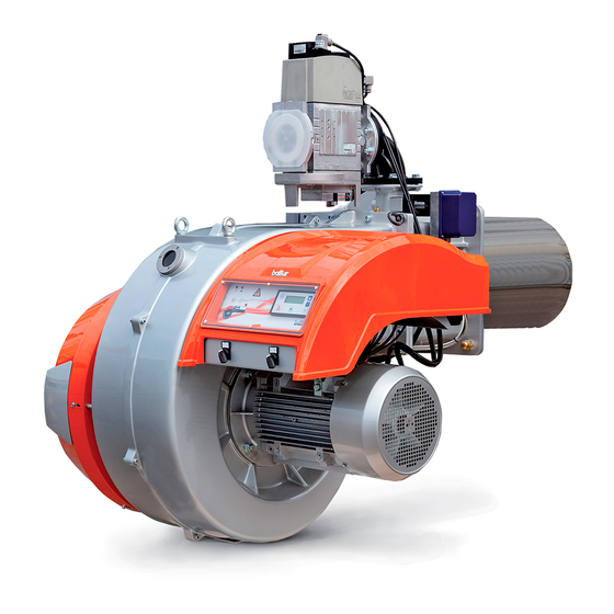
BRUCIATORI DI GAS BISTADIO PROGRESSIVO / MODULANTE
PROGRESSIVE/MODULATING TWO-STAGE GAS BURNERS
ITALIANO
TBG 800 MC
Manuale istruzioni per l'installazione, l'uso
IT
e la manutenzione
Instruction manual for
EN
installation, use and maintenance
ISTRUZIONI ORIGINALI (IT)
ORIGINAL INSTRUCTIONS (IT)
0006160209_201702
Advertisement
Chapters
Table of Contents

Related Manuals for baltur TBG 800 MC


Summary of Contents for baltur TBG 800 MC
- Page 1 BRUCIATORI DI GAS BISTADIO PROGRESSIVO / MODULANTE PROGRESSIVE/MODULATING TWO-STAGE GAS BURNERS ITALIANO TBG 800 MC Manuale istruzioni per l'installazione, l'uso e la manutenzione Instruction manual for installation, use and maintenance ISTRUZIONI ORIGINALI (IT) ORIGINAL INSTRUCTIONS (IT) 0006160209_201702...
-
Page 3: Table Of Contents
ITALIANO ITALIANO SOMMARIO Avvertenze per l'uso in condizioni di sicurezza ............................3 Caratteristiche tecniche ...................................6 Materiale a corredo ...................................7 Targa identificazione bruciatore.................................7 Dati registrazione prima accensione ..............................7 Descrizione componenti ..................................9 Dimensioni di ingombro ...................................10 Caratteristiche costruttive ................................11 Caratteristiche tecnico funzionali ..............................11 Applicazione del bruciatore alla caldaia ..............................12 Linea di alimentazione gas ................................13 Collegamenti elettrici .....................................14... - Page 4 ITALIANO DICHIARAZIONE DI CONFORMITÀ CE0085: DVGW CERT GmbH, Josef-Wirmer Strasse 1-3-53123 Bonn (D) Dichiariamo che i nostri bruciatori ad aria soffiata di combustibili gassosi e misti, serie: BPM...; BGN…; BTG…; TBML...; Comist…; GI…; GI…Mist; Minicomist…; Sparkgas...; TBG..; IB..; TBR... (Variante: … LX, per basse emissioni NOx; -V per inverter, FGR per ricircolazione esterna fumi) rispettano i requisiti minimi imposti dalle Direttive e Regolamenti europei: •...
-
Page 5: Avvertenze Per L'uso In Condizioni Di Sicurezza
ITALIANO AVVERTENZE PER L'USO IN CONDIZIONI sull'apparecchio. • L'apparecchio non è adatto a essere usato da persone (bambini DI SICUREZZA compresi) le cui capacità fisiche, sensoriali o mentali siano ridotte, oppure con mancanza di esperienza o di conoscenza. SCOPO DEL MANUALE •... - Page 6 • L’eventuale riparazione dei prodotti dovrà essere effettuata • Prima di avviare il bruciatore e almeno una volta all’anno, solamente da un centro di assistenza autorizzato da BALTUR o far effettuare da personale professionalmente qualificato le dal suo distributore locale, utilizzando esclusivamente ricambi seguenti operazioni: originali.
- Page 7 ITALIANO Avvertenze particolari per l’uso del gas. • L’alimentazione elettrica del bruciatore deve prevedere il neutro • Verificare che la linea di adduzione e la rampa siano conformi a terra. In caso di controllo della corrente di ionizzazione con alle norme e prescrizioni vigenti. neutro non a terra è...
-
Page 8: Caratteristiche Tecniche
ITALIANO CARATTERISTICHE TECNICHE MODELLO TBG 800 MC Potenza termica massima metano 8000 Potenza termica minima metano mg/kWh ¹) emissioni metano Classe 3 Funzionamento Bistadio progressivo modulante Trasformatore metano 50 hz 8kV - 30 mA - 230V Stm³/h Portata termica massima metano Stm³/h... -
Page 9: Materiale A Corredo
ITALIANO MATERIALE A CORREDO MODELLO TBG 800 MC Guarnizione isolante Prigionieri N°4 M20 Dadi esagonali N°4 M20 Rondelle piane N°4 Ø20 TARGA IDENTIFICAZIONE BRUCIATORE Logo aziendale Ragione sociale azienda Codice prodotto Modello bruciatore Matricola Potenza combustibili liquidi Potenza combustibili gassosi Pressione combustibili gassosi Viscosità... - Page 10 ITALIANO ¹) EMISSIONI GAS METANO ²) EMISSIONI GAS PROPANO Classi definite secondo la normativa EN 676. Emissioni CO metano / propano ≤ 100 mg/kWh Emissioni NOx in mg/kWh gas Emissioni NOx in mg/kWh gas Classe Classe metano propano ≤ 170 ≤...
-
Page 11: Descrizione Componenti
ITALIANO DESCRIZIONE COMPONENTI Testa di combustione Guarnizione Flangia attacco bruciatore Valvola farfalla gas Servomotore azionamento modulazione Sinottico Pressostato aria Gruppo serrande aria Quadro elettrico Cerniera Motore ventola Convogliatore aria in aspirazione Presa di pressione gas alla testa di combustione Modulatore regolazione aria - gas Dispositivo regolazione testa 9 / 34 0006160209_201702... -
Page 12: Dimensioni Di Ingombro
ITALIANO DIMENSIONI DI INGOMBRO Modello TBG 800 MC 1230 1000 2020 Modello E Ø F Ø IØ LØ N Ø TBG 800 MC DN 80 Modello TBG 800 MC 1300 10 / 34 0006160209_201702... -
Page 13: Caratteristiche Costruttive
ITALIANO CARATTERISTICHE COSTRUTTIVE CARATTERISTICHE TECNICO FUNZIONALI Il bruciatore risulta composto da: • Bruciatore di gas conforme alle normative europee EN 676 ed • Parte ventilante in lega leggera d'alluminio. alle Direttive Europee 2006/42/CE; 2014/30/UE; 2014/35/UE; • Ventilatore centrifugo per alte prestazioni. (UE) 2016/426. -
Page 14: Applicazione Del Bruciatore Alla Caldaia
ITALIANO APPLICAZIONE DEL BRUCIATORE ALLA CALDAIA MONTAGGIO GRUPPO TESTATA La testa di combustione viene imballata separatamente dal corpo ventilante. Fissare il gruppo testa al portellone caldaia nel seguente modo: • Posizionare sul canotto le guarnizioni isolanti (13). • Fissare la flangia del gruppo testa (15) alla caldaia (1) tramite i prigionieri, le rondelle, e i relativi dadi in dotazione (7). -
Page 15: Linea Di Alimentazione Gas
ITALIANO MONTAGGIO RAMPA GAS La rampa gas è omologata secondo normativa EN 676 e viene fornita separatamente. Per ottenere il miglior funzionamento del regolatore di pressione è opportuno che lo stesso, sia applicato sulla tubazione orizzontale, dopo il filtro. Il regolatore di pressione del gas, deve essere regolato, mentre il bruciatore lavora alla massima portata. -
Page 16: Collegamenti Elettrici
ITALIANO COLLEGAMENTI ELETTRICI • Tutti i collegamenti devono essere eseguiti con filo elettrico flessibile. • Le linee elettriche devono essere distanziate dalle parti calde. • L’installazione del bruciatore è consentita solo in ambienti con grado di inquinamento 2 come indicato nell’allegato M della norma EN 60335-1:2008-07. -
Page 17: Descrizione Del Funzionamento
ITALIANO DESCRIZIONE DEL FUNZIONAMENTO La rampa gas in dotazione è composta da una valvola di sicurezza in versione ON/OFF e da una valvola principale a singolo stadio ad apertura lenta. La regolazione della portata di combustibile in primo e in secondo stadio è... -
Page 18: Descrizione Del Funzionamento Amodulazione
ITALIANO DESCRIZIONE DEL FUNZIONAMENTO A MODULAZIONE Quando il bruciatore è acceso alla portata minima, se la sonda di modulazione lo consente (regolata ad un valore di temperatura o pressione superiore a quella esistente in caldaia) il servomotore di regolazione aria / gas inizia a girare; •... -
Page 19: Accensione E Regolazione
ITALIANO ACCENSIONE E REGOLAZIONE • Alla prima accensione possono verificarsi “blocchi” successivi dovuti a: - Lo sfogo dell’aria dalla tubazione del gas non è stato ISTRUZIONI PER IL FUNZIONAMENTO IN MODALITÀ eseguito correttamente e quindi la quantità di gas è MANUALE DEL BRUCIATORE. - Page 20 ITALIANO REGOLAZIONE DELLA POTENZA IN SECONDO STADIO La valvola a farfalla regolazione gas, viene tarata in fabbrica Dopo aver completato la regolazione della potenza di accensione, nella posizione "1" sulla leva. Se fosse necessario ridurre l'angolo di apertura della farfalla gas, posizionare lo snodo premere il pulsante (9) verso il simbolo in modo da raggiungere nella posizione "2".
- Page 21 ITALIANO • Il pressostato aria ha lo scopo di impedire l’apertura delle valvole gas se la pressione dell’aria non è quella prevista. Il pressostato deve essere regolato per intervenire chiudendo il contatto quando la pressione dell’aria nel bruciatore raggiunge il valore sufficiente.
-
Page 22: Misurazione Della Corrente Di Ionizzazione
ITALIANO MISURAZIONE DELLA CORRENTE DI IONIZZAZIONE Il pressostato di minima interviene arrestando il bruciatore che rimane in stand-by fino a quando la pressione si è ripristinata Il valore minimo della corrente di ionizzazione necessario a far entro i valori necessari per il funzionamento. funzionare l'apparecchiatura, è... -
Page 23: Apparecchiatura Di Comando E Controllo Per Bruciatori A Gas Lme73
ITALIANO APPARECCHIATURA DI COMANDO E CONTROLLO PER BRUCIATORI A GAS LME73... per ulteriori informazioni consultare la Guida rapida dell'apparecchiatura fornita a corredo con il manuale. Il pulsanate reset di blocco ') (pulsante info) (EK) è l'elemento operativo chiave per resettare il controllo del bruciatore Info e per attivare / disattivare le funzioni diagnostiche. - Page 24 ITALIANO PARTICOLARE MOTORE SQM 40 DI COMANDO MODULAZIONE PER REGOLAZIONE CAMMES Apertura massima aria (110°) Chiusura totale aria (bruciatore fermo) (10°) III Apertura minima aria (minore di camma IV) (20°) IV Apertura aria d'accensione (maggiore di camma III) (30°) Leva di inserzione ed esclusione accoppiamento motore- albero camme Indice di riferimento Albero camme...
-
Page 25: Regolazione Aria Sulla Testa Di Combustione
ITALIANO TBG 80 LX P / LX PN (V) TBG 80 LX ME / LX MC TBG 110 LX P / LX PN (V) TBG 110 LX ME / LX MC TBG 140 LX P / PN (V) TBG 140 LX ME / LX MC TBG 200 LX P / LX PN (V) TBG 200 LX ME / LX MC TBG 260 LX ME... -
Page 26: Manutenzione
ITALIANO MANUTENZIONE Effettuare almeno una volta all’anno e comunque in conformità alle norme vigenti, l’analisi dei gas di scarico della combustione verificando la correttezza dei valori di emissioni. • Pulire le serrande aria, il pressostato aria con presa di pressione ed il relativo tubo se presenti. -
Page 27: Tempi Di Manutenzione
ITALIANO TEMPI DI MANUTENZIONE Descrizione particolare Azione da eseguire TESTA DI COMBUSTIONE CONTROLLO VISIVO, INTEGRITA' CERAMICHE, SMERIGLIATURA ESTREMITA', VERIFICARE ELETTRODI ANNUO DISTANZA, VERIFICARE CONNESSIONE ELETTRICA DISCO FIAMMA CONTROLLO VISIVO INTEGRITA' EVENTUALI DEFORMAZIONI, PULIZIA ANNUO CONTROLLO VISIVO, INTEGRITA' CERAMICHE, SMERIGLIATURA ESTREMITA', VERIFICARE SONDA DI IONIZZAZIONE ANNUO DISTANZA, VERIFICARE CONNESSIONE ELETTRICA... -
Page 28: Vita Attesa
ITALIANO VITA ATTESA La vita attesa dei bruciatori e dei relativi componenti dipende molto dal tipo di applicazione su cui il bruciatore è installato, dai cicli, dalla potenza erogata, dalle condizioni dell’ambiente in cui si trova, dalla frequenza e modalità di manutenzione, ecc. ecc. Le normative relative ai componenti di sicurezza prevedono una vita attesa di progetto espressa in cicli e/o anni di funzionamento. -
Page 29: Precisazioni Sull'uso Del Propano
ITALIANO PRECISAZIONI SULL'USO DEL PROPANO PERICOLO / ATTENZIONE La potenza massima e minima (kW) del bruciatore, • Valutazione, indicativa, del costo di esercizio; è considerata con combustibile metano che coincide - 1 m3 di gas liquido in fase gassosa ha un potere calorifico approssimativamente con quella del propano. -
Page 30: Schema Di Principio Per Riduzione Pressione G.p.l. A Due Stadi Per Bruciatore Oppure Caldaia
ITALIANO SCHEMA DI PRINCIPIO PER RIDUZIONE PRESSIONE G.P.L. A DUE STADI PER BRUCIATORE OPPURE CALDAIA Manometro e presa di pressione Riduttore di 1° salto Riduttore di 2° salto Uscita ~ 1,5 bar Uscita ~ 30 hPa (mbar) Portata ~ il doppio del massimo richiesto Portata ~ il doppio del massimo richiesto dall’utilizzatore dall’utilizzatore... -
Page 31: Istruzioni Per L'accertamento Delle Cause Di Irregolarità Nel Funzionamento E La Loro Eliminazione
ITALIANO ISTRUZIONI PER L'ACCERTAMENTO DELLE CAUSE DI IRREGOLARITÀ NEL FUNZIONAMENTO E LA LORO ELIMINAZIONE IRREGOLARITÁ POSSIBILE CAUSA RIMEDIO Invertire l'alimentazione (lato 230V) del trasformatore di accensione e verificare Disturbo della corrente di con micro-amperometro analogico. ionizzazione da parte del Sostituire il sensore fiamma. trasformatore di accensione. -
Page 32: Schemi Elettrici
ITALIANO SCHEMI ELETTRICI 30 / 34 0006160209_201702... - Page 33 ITALIANO 31 / 34 0006160209_201702...
- Page 34 ITALIANO 32 / 34 0006160209_201702...
- Page 35 ITALIANO 33 / 34 0006160209_201702...
- Page 36 ITALIANO APPARECCHIATURA GNYE VERDE / GIALLO FOTORESISTENZA / ELETTRODO DI IONIZZAZIONE / FOTOCELLULA UV BRUNO PRESSOSTATO CONTROLLO TENUTA VALVOLE NERO RELE’ TERMICO CONNETTORE NERO CON SOVRASTAMPA FU1÷4 FUSIBILI SPIA DI FUNZIONAMENTO SPIA DI BLOCCO Terra LAMPADA BLOCCO RELE’ TERMICO MOTORE L1 - L2- L3 Fasi VENTOLA N - Neutro...
- Page 37 ENGLISH ENGLISH SUMMARY Warnings for use in safety conditions ..............................3 Technical specifications ...................................6 Standard accessories ..................................7 Burner identification plate ..................................7 Data recorded during first start-up ..............................7 Component description ..................................9 Overall dimensions ..................................10 Design characteristics ..................................11 Technical functional characteristics ..............................11 Burner connection to the boiler ................................12 Gas supply line ....................................13 Electrical connections ....................................14...
- Page 38 ENGLISH DECLARATION OF CONFORMITY CE0085: DVGW CERT GmbH, Josef-Wirmer Strasse 1-3-53123 Bonn (D) We hereby declare under our own responsibility, that our blown air burners fired by gas and dual fuel, series: BPM...; BGN…; BTG…; TBML...; Comist…; GI…; GI…Mist; Minicomist…; Sparkgas...; TBG..; IB..; TBR... (Variant: …...
-
Page 39: Warnings For Use In Safety Conditions
ENGLISH WARNINGS FOR USE IN SAFETY have access to, through a responsible person, the information concerning their safety, surveillance and instructions concerning CONDITIONS equipment use. • Children must be watched over to prevent them from playing PURPOSE OF THIS MANUAL with the equipment. - Page 40 Contact only qualified personnel. accordance with the law in force. • Any product repairs must only be carried out by BALTUR - Check the adjustment and safety devices are working authorised assistance centres or by its local distributor using properly.
- Page 41 ENGLISH Special precautions when using gas. with certain fundamental rules, including the following: • Check that the feed line and the train comply with current law - do not touch the equipment with parts of the body that are and regulations. wet or damp or with damp feet;...
-
Page 42: Technical Specifications
ENGLISH TECHNICAL SPECIFICATIONS MODEL TBG 800 MC Maximum natural gas heat power 8000 Minimum natural gas heat power mg/kWh ¹) natural gas emissions Class 3 Operation Two-stage progressive / modulating 50 Hz natural gas transformer 8kV - 30 mA - 230V Stm³/h... -
Page 43: Standard Accessories
ENGLISH STANDARD ACCESSORIES MODEL TBG 800 MC Insulating gasket Stud bolts N°4 M20 Hexagon nuts N°4 M20 Flat washers N°4 Ø20 BURNER IDENTIFICATION PLATE Company logo Company name Product code Burner model Serial number Liquid fuel power Gaseous fuel power... - Page 44 ENGLISH ¹) NATURAL GAS EMISSIONS ²) PROPANE GAS EMISSIONS Classes defined according to EN 676 standards. Propane / natural gas CO emissions ≤ 100 mg/kWh NOx emissions in mg/kWh natural NOx emissions in mg/kWh Class Class propane gas ≤ 170 ≤...
-
Page 45: Component Description
ENGLISH COMPONENT DESCRIPTION Combustion head Seal Burner connection flange Gas throttle valve Modulator activation servomotor Synoptic control panel Air pressure switch Air gate unit Electrical panel Hinge Fan motor Intake air conveyor Gas pressure port to combustion head Adjusting air/gas modulator Combustion head adjustment device 9 / 34 0006160209_201702... -
Page 46: Overall Dimensions
ENGLISH OVERALL DIMENSIONS Model TBG 800 MC 1230 1000 2020 Model E Ø F Ø IØ LØ N Ø TBG 800 MC DN 80 Model TBG 800 MC 1300 10 / 34 0006160209_201702... -
Page 47: Design Characteristics
ENGLISH DESIGN CHARACTERISTICS TECHNICAL FUNCTIONAL CHARACTERISTICS The burner consists of: • Gas burner compliant with the European standards EN 676 • Ventilating part in light aluminium alloy. and with the European Directives 2006/42/CE; 2014/30/UE; • Centrifugal fan for high performances. 2014/35/UE;... -
Page 48: Burner Connection To The Boiler
ENGLISH BURNER CONNECTION TO THE BOILER HEAD UNIT ASSEMBLY The combustion head is packaged separately from the body of the burner. Anchor the head unit to the boiler door as follows: • Position the insulating seals on the sleeve (13). •... -
Page 49: Gas Supply Line
ENGLISH ASSEMBLING THE GAS TRAIN The EN 676 approved gas train is sold separately from the burner. To ensure optimal functioning of the pressure regulator, it should be applied to the horizontal pipe after the filter. The gas pressure regulator must be regulated when the burner is working at the maximum flow. -
Page 50: Electrical Connections
ENGLISH ELECTRICAL CONNECTIONS • It is advisable to make all connections with flexible electric wire. • The power lines must be distanced from the hot parts. • The burner installation is allowed only in environments with pollution degree 2 as indicated in annex M of the EN 60335- 1:2008-07 regulation. -
Page 51: Operating Description
ENGLISH OPERATING DESCRIPTION The gas train supplied is composed of an ON/OFF safety valve and a single stage slow opening main valve. The gas flow adjustment in the first and second stage is carried out by a streamlined butterfly valve (6) activated by the electric servomotor (7). -
Page 52: Modulation Operation Description
ENGLISH MODULATION OPERATION DESCRIPTION When the burner is ignited at the minimum flow-rate, if the modulation probe allows it (adjusted to a temperature or pressure which is greater than that present in the boiler) the air adjustment servomotor begins to operate, •... -
Page 53: Starting Up And Regulation
ENGLISH STARTING UP AND REGULATION instability in the ionisation area, due to an incorrect air/gas ratio. • Correct the air flow acting on the screw(s) (11), where the INSTRUCTIONS FOR MANUAL BURNER OPERATION. bearing (12) is located: Combustion may be checked throughout the entire burner - in a clockwise direction the air flow increases operating range by controlling the equipment manually. - Page 54 ENGLISH SECOND STAGE POWER REGULATION. After having completed the ignition power adjustment, press key (9) towards symbol in order to reach air and gas maximum delivery.Check that the electric servomotor second stage gas flow rate regulation cam is positioned at 130°. •...
- Page 55 ENGLISH • The air pressure switch prevents the opening of the gas valves if the air pressure is not the foreseen one. The pressure switch must be adjusted to intervene closing the contact when the air pressure in the burner reaches a sufficient value. If the air pressure switch does not detect a pressure greater than that calibrated, the equipment runs through its cycle but does not switch on the ignition transformer and does not open the gas...
-
Page 56: Ionisation Current Measurement
ENGLISH IONISATION CURRENT MEASUREMENT The minimum value pressure switch stops the burner that remains on standby until the pressure is restored within the values required The maximum ionisation current value required for a correct for operation. operation of the equipment is indicated in the wiring diagram. After that, the burner re-starts in an autonomous way following the The burner provides a significantly higher current and therefore ignition sequence. -
Page 57: Lme73 Gas Burner Control Device
ENGLISH LME73 GAS BURNER CONTROL DEVICE ... for more information, refer to the machine quick Guide supplied with the manual. The lock out reset push button 1) (info push button) (EK) is the key element to reset the burner control and activate/ Info deactivate the diagnostics functions. -
Page 58: Detail Of The Modulation Control Motor Sqm 40 For Cam Adjustment
ENGLISH DETAIL OF THE MODULATION CONTROL MOTOR SQM 40 FOR CAM ADJUSTMENT Maximum air opening (110°) Total air closure (burner stopped) (10°) III Minimum air opening (lower than cam IV) (20°) IV Ignition air opening (greater than cam III) (30°) Lever for enabling/disabling motor-camshaft coupling Reference scale Camshaft... -
Page 59: Air Regulation On The Combustion Head
ENGLISH TBG 80 LX P / LX PN (V) TBG 80 LX ME / LX MC TBG 110 LX P / LX PN (V) TBG 110 LX ME / LX MC TBG 140 LX P / PN (V) TBG 140 LX ME / LX MC TBG 200 LX P / LX PN (V) TBG 200 LX ME / LX MC TBG 260 LX ME... -
Page 60: Maintenance
ENGLISH MAINTENANCE Analyse combustion gases and check that the emission values are correct at least once a year, in compliance with current law. • Clean air dampers, the air pressure switch with pressure port and the relevant pipe, if any. •... -
Page 61: Maintenance Time
ENGLISH MAINTENANCE TIME Part description Action to be performed COMBUSTION HEAD VISUAL INSPECTION OF THE INTEGRITY OF CERAMICS. TIP GRINDING, CHECK DISTANCE, ELECTRODES YEARLY CHECK ELECTRICAL CONNECTION FLAME DISC INTEGRITY VISUAL CHECK FOR ANY DEFORMATIONS, CLEANING, YEARLY VISUAL INSPECTION OF THE INTEGRITY OF CERAMICS. TIP GRINDING, CHECK DISTANCE, IONISATION PROBE YEARLY CHECK ELECTRICAL CONNECTION... -
Page 62: Expected Lifespan
ENGLISH EXPECTED LIFESPAN The expected lifespan of burners and relevant components depends very much from the type of application on which the burner is installed, from cycles ,of delivered power, from the conditions of the environment in which it is located, from maintenance frequency and mode, etc. -
Page 63: Specifications For Propane Use
ENGLISH SPECIFICATIONS FOR PROPANE USE DANGER / ATTENTION The maximum and minimum power (kW) of the burner • Operating costs approximate assessment; refers to natural gas which is more or less the same as with - 1 m3 of liquid gas in gaseous stage has a lower heating propane. -
Page 64: Block Diagram Illustrating The Principle Of L.p.g. Pressure Reduction In Two Stages For Burner Or Boiler
ENGLISH BLOCK DIAGRAM ILLUSTRATING THE PRINCIPLE OF L.P.G. PRESSURE REDUCTION IN TWO STAGES FOR BURNER OR BOILER Pressure gauge and pressure intake 1st step reducer 2nd step reducer Output ~ 1.5 bar Output ~ 30 hPa (mbar) Flow rate ~ double the maximum required by the Flow rate ~ double the maximum required by user the user... -
Page 65: Instructions For Determining The Cause Leading To Irregularities In The Operation And Their Elimination
ENGLISH INSTRUCTIONS FOR DETERMINING THE CAUSE LEADING TO IRREGULARITIES IN THE OPERATION AND THEIR ELIMINATION IRREGULARITY POSSIBLE CAUSE REMEDY Invert the ignition transformer power supply (230V side) and check using an Disturbance to ionization current analogue micro-ammeter. from the ignition transformer. Replace the flame sensor. -
Page 66: Wiring Diagrams
ENGLISH WIRING DIAGRAMS 30 / 34 0006160209_201702... - Page 67 ENGLISH 31 / 34 0006160209_201702...
- Page 68 ENGLISH 32 / 34 0006160209_201702...
- Page 69 ENGLISH 33 / 34 0006160209_201702...
- Page 70 ENGLISH APPARECCHIATURA GNYE GREEN / YELLOW PHOTORESISTOR / IONISATION ELECTRODE / UV BLUE PHOTOCELL BROWN VALVE SEAL CONTROL PRESSURE SWITCH BLACK THERMAL RELAY BLACK CONNECTOR WITH OVERPRINT FU1÷4 FUSES OPERATION INDICATOR LIGHT LOCK-OUT WARNING LIGHT Ground FAN MOTOR THERMAL SWITCH RELAY LOCK-OUT L1 - L2- L3 Phases LAMP N - Neutral...
- Page 72 BALTUR S.P.A. Via Ferrarese, 10 44042 Cento (Fe) - Italy Tel. +39 051-6843711 Fax. +39 051-6857527/28 www.baltur.it info@baltur.it Il presente catalogo riveste carattere puramente indicativo. La casa, pertanto, si riserva ogni possibilità di modifica dei dati tecnici e di quant'altro in esso riportato.
Need help?
Do you have a question about the TBG 800 MC and is the answer not in the manual?
Questions and answers