Table of Contents
Advertisement
Quick Links
If you have a problem, question, or request, call
your local dealer, or Steelcase Line 1 at
888.STEELCASE (888.783.3522)
for immediate action by people who want to help you.
(Outside the U.S.A., Canada, Mexico, Puerto Rico,
and the U.S. Virgin Islands, call: 1.616.247.2500)
Or visit our website: www.steelcase.com
© 2005 Steelcase Inc.
Grand Rapids, MI 49501
U.S.A.
Printed in U.S.A.
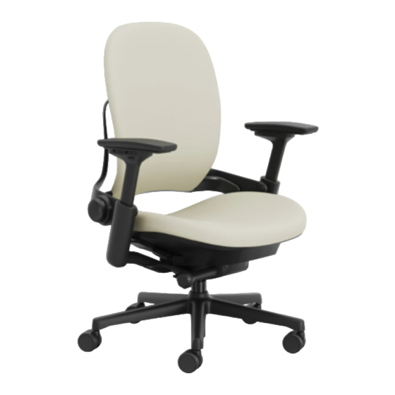
462 Leap
®
Plus Chair Back Assembly Replacement
Lumbar Installation/Replacement
Lumbar Resistance Replacement
or a flat-bladed
screwdriver that is 8"
or longer
Page 1 of 8
939546233 Rev B
Advertisement
Table of Contents

Related Manuals for Steelcase 462 Leap Plus


Summary of Contents for Steelcase 462 Leap Plus
- Page 1 8" or longer If you have a problem, question, or request, call your local dealer, or Steelcase Line 1 at 888.STEELCASE (888.783.3522) for immediate action by people who want to help you. (Outside the U.S.A., Canada, Mexico, Puerto Rico, and the U.S.
- Page 2 Chair Back Replacement Slide seat fully forward while holding the seat slide lever. Locate the black quick release tab located on the left hand side of the chair (as you sit in it) between the plates. Lift the quick release tab while pulling the seat slide lever and sliding the seat forward.
- Page 3 Black and Midnight With the arm adjusted all the way up, remove the outer pod cover and arm by one of the following methods: a) For black and midnight colored chairs pull the pod cover out from the bottom thus releasing it from the inside cover and clearing the steel bracket.
- Page 4 Unscrew two (2) front screws to remove the control cover. NOTE: After control cover screws are removed, the chair back is free to move. Hold chair back firmly to avoid possible injury. CONTROL COVER Page 4 of 8 939546233 Rev B...
- Page 5 BACK RIBBON Remove the j-channel from the back channel slot using a flat-bladed screwdriver to begin the removal process. Remove (2) screws from back shell located under the BACK CHANNEL back ribbon. SLOT Pull up & out on the cushion to remove the cushion from the back shell.
- Page 6 Pop screw covers out (10a) and remove upper pivot screws (10b). Remove lower pivot screws. Reverse steps to reassemble. NOTE: Pod covers and caps should be reassembled prior to the arms. Page 6 of 8 939546233 Rev B...
- Page 7 Lumbar Resistance Mechanism Replacement Remove two (2) screws (1a) and knob (1b). Align spring loop with pin and rotate toward floor (right) to align and lock in place. Replace two (2) screws LOOP removed in step 1. LUMBAR RESISTANCE KNOB ALIGNING PEGS Page 7 of 8 939546233 Rev B...
- Page 8 Lumbar Installation Pull back down from bottom. Insert lumbar between cushion and backshell. Raise one side over tabs and slide all the way down. Repeat on other side. Slide lumbar toward bottom. Tip end to dislodge from teeth. Lumbar Replacement Move lumbar up as high as you can.
Need help?
Do you have a question about the 462 Leap Plus and is the answer not in the manual?
Questions and answers