
Related Manuals for Side-Power SEP Series


Summary of Contents for Side-Power SEP Series
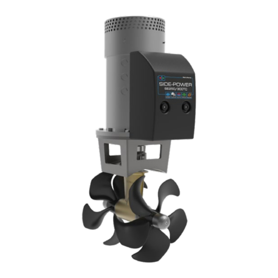
- Page 1 - 250/300 - 300/300 Installation Manual SLEIPNER MOTOR AS P.O. Box 519 N-1612 Fredrikstad Norway Document id: 5246 www.side-power.com Revision: Date: 2020 © Sleipner Motor AS 2020...
-
Page 2: Table Of Contents
Contents Bow Installation Instructions Products Bow Installation Considerations and Precautions ..... 3 SEP300/300TC - SEP300 tunnel thruster 48v Thruster Measurements ............4 SEP250/300TC - SEP250 Tunnel thruster, 24v Thruster Specifications .............. 5 Technical Specifications ............5 Positioning of the tunnel / thruster ..........6 Tunnel Length ................ -
Page 3: Bow Installation Considerations And Precautions
S-link control system without the designated and approved interface will render all warranties and responsibilities for the complete line of Side-Power products connected void and null. If you are interfacing by agreement with Sleipner and through a designated Side-Power supplied interface, you are still required to also install at least one original Side-Power control panel to enable effi... -
Page 4: Thruster Measurements
Propeller position will vary with each thruster model Twin Propeller The gear leg/ propeller(s) must never extend out of the tunnel Tunnel centre line MG_0075 Thruster Measurements MC_0126 *250 *300 Measurement Measurement description code inch inch Internal tunnel diameter 11,81 11,81 Motor Height 19,29... -
Page 5: Thruster Specifications
Thruster Specifi cations MC_0140 description * 250 * 300 Available DC System (v) 24v & 48v Thrust 12v or 24v (kg * lbs) 300 kg * 661 lbs 350 kg * 749 lbs Thrust 10.5v or 21v (kg * lbs) 250 kg * 551 lbs 300 kg * 661 lbs Typical Boat Size (m * ft) -
Page 6: Positioning Of The Tunnel / Thruster
Pivot point important Lowered rotation power performance Stronger rotation power performance Water line Ø min 1/4 Ø (Recommended) min 1/4 Ø (Recommended) MG_0001 Positioning of the tunnel / thruster MC_0003 Aim to install the thruster as far forward as possible (1) Due to the leverage eff... -
Page 7: Tunnel Length
Do not allow the variable length of the tunnel walls to vary in length excessively. EG. the top tunnel wall is x 4 longer than the bottom wall. Water flow must have space to "straighten" itself for best Cavitation performance. -
Page 8: Tunnel Installation In Sailboats
Pos. A Pos. B MG_0004 Tunnel installation in sailboats MC_0003 Some sail boats have a fl at bottom and shallow draft in the bow section. This can make installing the thruster as far forward from the boats main pivot point diffi... -
Page 9: Water Deflection
High water force while underway High water force while underway from wave contact MG_0003 Water Defl ection MC_0003 A possible problem in sail boats or fast powerboats is that a non-rounded surface can generate drag from the back face of the tunnel, as it creates “fl at”... -
Page 10: Tunnel Ends
This “free” extra thrust in optimal installations be 30 - 40% of the total thrust. (NB: A Side-power thruster propeller does not produce cavitation at working speed. Therefore, any cavitation and cavitation noise in the tunnel will be caused during improper tunnel installation.) SEP 250 &... -
Page 11: Tunnel Installation
8 x layers of fiberglass and resin 8 x layers of fiberglass and resin MG_0005 Tunnel Installation MC_0003 IMPORTANT We recommend that a professional does the fi breglass, steel or aluminium fi tting of the tunnel. These instructions are only general instructions and do not explain in any way the details of fi... - Page 12 You must apply gel coat to areas you have grounded/ moulded to make waterproof. These areas allow water access to the hull which is typically not waterproof without these applications outside. (NB: All original Side-Power tunnels are fully waterproof when delivered except in the areas where you have cut and bonded it to the hull.)
-
Page 13: Stern Tunnel Installation
Stern Tunnel Installation MC_0003 Stern thruster installation has extra considerations and precautions and thruster installation procedures. See the attached manual supplied in the stern thruster kit SEP 250 & SEP 300 5246 2020... -
Page 14: Thruster Installation Considerations And Precautions
S-link control system without the designated and approved interface will render all warranties and responsibilities for the complete line of Side-Power products connected void and null. If you are interfacing by agreement with Sleipner and through a designated Side-Power supplied interface, you are still required to also install at least one original Side-Power control panel to enable effi... -
Page 15: Gear Leg & Motor Bracket Installation
2 - 4 PORT STARBOARD Measurement Boats ØC Boats centre line Description centre line inch Tunnel ØA 2.05 centre line 1.89 Tunnel ØC 0.43 centre line *P- Propositional ØA Stern PORT STARBOARD Gasket Ensure propeller turns without obstruction Apply MS Polymer sealant or equal to 6 - 7 both sides of the... -
Page 16: Propeller Installation
DRIVE PIN PROPELLER WASHER LOCK NUT Anti-fouling ANODE Apply Loctite 243 or similar ANODE HOLDING SCREW MG_0033 Propeller Installation MC_0264 ! Please refer to the graphic for special considerations relating to your model ! Centre the drive pin and Insert the propeller onto the shaft spine. Rotate the propeller until the drive pin aligns with the internal slot in the propeller. IMPORTANT For twin counter-rotating gear legs, propellers are marked with P (Port) and S (starboard) and must be installed appropriately. -
Page 17: Motor Installation
IMPORTANT Ensure the holding key and coupling are aligned when fitted Holding Key > 30° Motor FASTEN (33 Nm) (24 lb/ft) IMPORTANT Do not position support on the motor cap. Motor support MG_0058 Motor Installation MC_0019 ! Please refer to the graphic for special considerations relating to your model ! Install the motor onto the motor bracket ensuring the couplings are engaged together correctly (top and bottom). -
Page 18: Thruster Electrical Installation
IMPORTANT The Proportional Power Controller is a bulkhead (wall) mounted unit and must be installed in a dry and well-ventilated compartment. The unit also requires a 200mm minimum head clearance, 150mm minimum 200mm bottom clearance and a 100mm minimum clearance surrounding its remaining outer casing. -
Page 19: Electrical Specifications
Electrical Specifi cations MC_0044 SEP 250 & SEP 300 5246 2020... -
Page 20: Control Panel Cable Installation
PJC 212 PJC 212 Proportional Proportional joystick joystick 8730 8730 control panel control panel Bow and stern Bow and stern S-link external S-link external S-link external link external Observe PPC battery switch interface switch interface switch interface switch interface St ation 1 Station 2 and remote and remote... -
Page 21: S-Link Planning & Precautions
Example of the control wiring with You need: Control Panel S-link system for boats with one 2 x 6 1327 End terminators Wiring of S-link system 3 x 6 1326 T-connectors control position and one thruster. 1 x 6 1328 Power spur 2 x 6 1320-xxM Backbone cables 2 x 6 1321-xxM Spur cables Explaining S-link... - Page 22 Technical Wiring Diagram MG_0062 SEP 250 & SEP 300 5246 2020...
-
Page 23: Technical Wiring Diagram
Technical Wiring Diagram For 300 size thrusters Wiring diagram example 8730 PJC 211/212 PJC 211/212 GW-1 Proportional S-link external S-link external Proportional S-link Gateway S-link Gateway joystick switch interface switch interface joystick (optional) (optional) control panel and remote and remote control panel Bow/stern (optional) -
Page 24: Control Panel Installation
4x SCREWS Ø 4.5 mm Ø 4.5 mm 75.7 mm 58 mm 67 mm GASKET Ø 4.5 mm Ø 4.5 mm Ø 4.5 mm External alarm / buzzer connection (S-link) Supply + 12V / 24V DC Internal fuse / relay External alarm buzzer 12V / 24V DC - max 0,5A MG_0063... -
Page 25: Pre-Delivery Checklist
Pre-delivery Checklist MC_0033 ..The bolts holding the gear house and motor bracket together are tightened correctly... The bolts holding the motor to its bracket are tightened correctly... All electrical connections are clean, dry and tight, and the correct cable, fuse and main switch size. -
Page 26: Spare Parts
Spare Parts MC_0024 For the most up to date documentation, we advise you to visit our website www.side-power.com for the spare parts list. Product Templates and Additional Resources MC_0024 For additional supporting documentation, we advise you to visit our website www.side-power.com... - Page 27 Notes MC_0037 ..............................................................................................................................................................................................................................................................................................................................................................................................................................................................................................................................................................................................................................................................................................................................................................................................................................................................................................................................................................................................................................................................................................................................................................................................................................................................................................................................................................................................................................................................................................................................................................................................................SEP 250 & SEP 300 5246 2020...
- Page 28 Worldwide sales and service www.side-power.com SLEIPNER MOTOR AS P.O. Box 519 N-1612 Fredrikstad Norway The information given in the document was correct at the time it was published. However, Sleipner Motor AS can not accept liability for any inaccuracies or omissions it may contain.
Need help?
Do you have a question about the SEP Series and is the answer not in the manual?
Questions and answers