Table of Contents
Advertisement
Quick Links
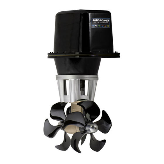
SE 130/250T IP
Ignition Protected
SIDE-POWER
thruster assembly
Thruster Systems
Installation and user manual
2175 NW 34th Ave Miami, FL 33142 USA
Phone: 786-621-3010 • Fax: 786-621-3046
Website: https://yachtaidmarine.com/product-category/marine-bow-thrusters/
Email: info@yachtaidmarine.com
https://yachtaidmarine.com/product-category/marine-bow-thrusters/
Advertisement
Table of Contents

Related Manuals for Side-Power SE 130/250T IP


Summary of Contents for Side-Power SE 130/250T IP
- Page 1 SE 130/250T IP Ignition Protected SIDE-POWER thruster assembly Thruster Systems Installation and user manual 2175 NW 34th Ave Miami, FL 33142 USA Phone: 786-621-3010 • Fax: 786-621-3046 Website: https://yachtaidmarine.com/product-category/marine-bow-thrusters/ Email: info@yachtaidmarine.com https://yachtaidmarine.com/product-category/marine-bow-thrusters/...
-
Page 2: Table Of Contents
Contents Technical specifications ............. 2 DECLARATION OF CONFORMITY Planning & important precautions..........3 Stern thruster installation considerations........3 We, Sleipner Motor AS Bolt on installation ..............4 P.O. Box 519 Mould on installation ..............5 N-1612 Fredrikstad, Norway Gearhouse and motorbracket ............ 6 declare that this product with accompanying Oil tank &... -
Page 3: Planning & Important Precautions
Planning and important precautions Prior to installation, it is important that the installer reads this guide to ensure necessary acquaintance with this product. The electromotor assembly must be handled carefully. Do not lift it by the internal connections or put it down on the driveshaft. Beware to keep installation within adviced measurements. -
Page 4: Bolt On Installation
SEALANT Fig. 2 Fig. 1 WASHERS LOCKNUT OR DOUBLE NUTS SEALANT Bolt on installation of the stern tunnel 1. Make sure that there are enough space both inside and out- If a bow thruster is also installed, we strongly advice to side the transom of the boat. -
Page 5: Mould On Installation
Fig. 1 Fig. 2 Grind off the bolt flange and Bond multiple layers both in- the gelcoat both inside and out- side and outside side in the areas shown. Boat transom Boat transom Stern tunnel Mould on installation of the stern tunnel 1. -
Page 6: Gearhouse And Motorbracket
Fig. 1 Fig. 1 Fig. 2 Fig. 3 SP 75 Ti SP125Ti BOATS SP 95 Ti CENTRELINE BOATS CENTRELINE TUNNELS CENTRELINE TUNNELS CENTRELINE Ø 9mm 0,35" 28,0mm Ø 32mm Ø 11,00mm 1,1" 1,26" 7/16" Ø 46,00mm 1,81" 40,0mm 1,57" Fig. 4 Fig. -
Page 7: Oil Tank & Propellers
Locktite Fitting propellers 1. Turn the propeller shaft so that the drivepin (5) is in a horizontal position and ensure that it is centred in the propellershaft. 2. Push the propellers onto the shaft with the track for the drivepin in an horizontal position (same direction as you set the drivepin), all the way in. -
Page 8: Electromotor Ip Assembly
Bolt tightening force (4x): SP75Ti: 33 Nm (24 lb/ft) SP95Ti: 33 Nm (24 lb/ft) Fig. 1 Bolt tightening force (2x): SP95Ti IP SP75Ti: 17 Nm (12,4 lb/ft) SP795Ti: 17 Nm (12,4 lb/ft) Bolt tightening force (4x): Fitting the electromotor IP assembly 33 Nm (24 lb/ft) Remove the 4 bolts in the motorbracket. -
Page 9: Electrical Installation
Counter Nut Counter Nut Counter Nut Washer Washer Washer Cable terminal Cable terminal Cable terminal Counter Nut Washer Washer Washer Counter Nut Counter Nut Counter Nut Washer Cable terminal Washer RED: Washer Washer Washer BLACK: - Counter Nut Battery Battery Battery Washer 12V or 24V... -
Page 10: Control Panel And Control-Leads
Pin configuration in contacts SIDEPOWER SIDEPOWER THRUSTER THRUSTER SLEIPNER SLEIPNER Control panel and control-leads Control panel and control-leads • You can install as many panels as you wish by using optional Y-connectors. If two or more panels are operated at the same time in •... -
Page 11: "Visual" Wiring Diagram
"Visual" wiring diagram SP75Ti / SP95Ti ignition protected thruster assembly SE130/250T IP Ignition Protected thruster assembly versjon1.3 - 2015 1.2.1 - 2007 https://yachtaidmarine.com/product-category/marine-bow-thrusters/... -
Page 12: Technical Wiring Diagram
Technical wiring diagram 4 pin On Motor connector Fused blue red (+) inside 1A (sig -) blue (sig +) Electronic interface box 6 1232i 6 1230i white black (-) grey (sig +) grey (sig -) black brown Battery Fuse main Thermal switch switch... -
Page 13: Checklist
Checklist Propeller is fastened correctly to the shaft. Propeller turns freely in tunnel. Lower-unit is filled with gearoil. Oil-drain screw is tightened and the copper seal is present. The zinc-anode holding screw is tightened well with thread glue. ... -
Page 14: Important User Precautions
Important user precautions • Ensure that you know the location of the main battery switch that disconnects the thruster from all power sources (batteries) so that the thruster can be turned off in case of a malfunction. • Always turn the main power switch off before touching any part of the thruster, as an incidental start while touching moving parts can cause serious injuries. -
Page 15: How To Use Sidepower Thrusters
To turn panel ON Turn boat to port Bow+Stern Thruster To turn panel OFF Turn boat to starboard How to use Sidepower thrusters How to use Sidepower thrusters How to use a bowthruster How to use a bowthruster 1. Turn main power switch for the bowthruster on. (Always turn off the main power switch when not onboard.) 1. -
Page 16: Maintenance
Power & control cables Ignition protected casing Motorbracket for holding motor and gearhouse together on the tunnel. Flexible coupling secures the electromo- tor if propeller is jammed. Changeable from inside the boat. 5-blade skew Q-PROP propeller for ultimate performance. Prefilled &sealed gearleg. Changeable zincanode protects gear- house from corrosion in seawater. -
Page 17: Troubleshooting
Trouble shooting Before seeking assistance at the help desk of your Sidepower dealer / distributor please perform these tests and make notes of all mea- surements to ensure that they have as much information as possible to work on. NB! All check points and solutions must be carried out after consulting the relevant information elsewhere in this manual to under-stand how the system is intended to work. -
Page 18: Warranty Statement
Warranty statement 1. The equipment manufactured by Sleipner Motor AS (The “Warrantor”) is warranted to be free from defects in workmanship and materials under normal use and service. 2. This Warranty is in effect for of two years (Leisure Use) or one year (Commercial use) from the date of purchase by the user. Proof of purchase must be included, to establish that it is inside the warranty period. -
Page 19: Parts List
SE130/250T IP SE130/250T IP Ignition Protected thruster assembly versjon1.3 - 2015 https://yachtaidmarine.com/product-category/marine-bow-thrusters/... -
Page 20: Service Centres
Worldwide sales and service 2175 NW 34th Ave Miami, FL 33142 USA Phone: 786-621-3010 • Fax: 786-621-3046 Website: https://yachtaidmarine.com/product-category/marine-bow-thrusters/ Email: info@yachtaidmarine.com https://yachtaidmarine.com/product-category/marine-bow-thrusters/...
Need help?
Do you have a question about the SE 130/250T IP and is the answer not in the manual?
Questions and answers