
Related Manuals for Side-Power SE100


Summarization of Contents
Bow Installation Considerations and Precautions
Electrical Compartment & Ventilation Needs
Thruster must not be in ignition-proof compartments; consider carbon dust and ventilation.
Location, Hull Integrity & Protection
Mounting angle, support for off-vertical motors, avoiding hull stiffener cuts, keeping components dry.
Finishing and Antifouling Application
Apply antifouling to gearhouse/propellers, avoid tunnel interior finishing.
Thruster Installation Considerations and Precautions
Handling, Electrical Circuit & Operation Rules
Handle with care, include fuse/switch, never run thruster out of water.
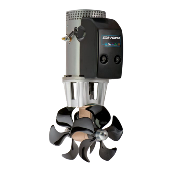
Technical Specifications
Motor, Gearhouse, Tunnel & Propeller Details
Describes motor, gearhouse material, tunnel construction, and propeller type.
Battery Capacity & Duty Cycle Recommendations
Minimum battery capacity and maximum usage time guidelines.
Key Safety Features Overview
Details electronic time-lapse, thermal cut-off, flexible coupling, and panel auto-off.
Positioning of the Tunnel / Thruster
Forward Placement for Leverage and Power
Aim to install thruster forward for optimal leverage and rotation power.
Underwater Depth for Efficiency and Noise Reduction
Install deep to prevent air suction, improve thrust, and reduce noise.
Tunnel Length
Optimal Length, Shape & Cavitation Factors
Depends on hull type, environment; avoid lengths >4x diameter; consider friction and cavitation.
Thruster Positioning Within Tunnel Requirements
Propellers and gear leg must be entirely inside the thruster tunnel.
Hull Type Specific Length Adjustments
Standard, flat bottom, and high-speed hull considerations for tunnel length.
Tunnel installation in sailboats
Sailboat Hull Adaptations
Method for installing in sailboats with flat bottoms and shallow drafts using deflectors.
Water Deflection
Reducing Tunnel Drag and Water Noise
Addresses drag from non-rounded tunnel faces and noise from water flow.
Hull Modifications for Water Flow
Solutions using hull recesses or deflectors to reduce drag and protect thruster.
Preventing Thruster Damage from Water Forces
Protects thruster from high water speeds, turning, or wave impacts.
Tunnel ends
Benefits of Rounded Tunnel Ends for Performance
Maximizes thrust, minimizes noise and cavitation via rounded connections.
Angled Tunnel Ends for Metal Hulls
Angled tunnel ends offer performance similar to rounded ones for steel/aluminium hulls.
Vacuum Effect from Rounded Ends for Sideways Thrust
Rounded ends create a vacuum for additional sideways thrust.
Tunnel installation
Hull Preparation, Marking & Drilling
Finding position, marking, drilling, grinding gel coat for tunnel fitting.
Tunnel Fitting, Securing & Fiberglassing
Inserting, marking, cutting, and casting the tunnel into the hull with fiberglass.
Gear Leg & Motor Bracket Installation
Positioning, Gasketing & Drive Alignment
Marking, using gaskets, ensuring propeller clearance, and drive alignment.
Sealing, Fastening & Torque Specifications
Applying sealant, securing gear leg/bracket with specified torque.
Propeller Installation
Propeller Mounting, Drive Pin & Lock Nut
Centering drive pin, aligning propeller, and installing lock nut.
Anode Installation & Antifouling Application
Installing anode and applying antifouling to specified parts.
Motor Installation
Motor Mounting & Coupling Engagement
Installing motor onto bracket, ensuring couplings engage correctly.
Support for Angled Motor Mounting
Requirement for separate support if motor is angled more than 30 degrees.
Securing Motor to Bracket & Torque
Fastening motor bolts to the bracket with specified torque.
Thruster Electrical Installation
Cable Sizing, Battery Capacity & Fusing
Using appropriate cables, batteries, and slow-blow fuses for the thruster.
Main Switch, Fuse & Cable Lug Requirements
Installing main switch, ensuring accessibility, and proper cable lug fitting.
Control Panel Cable Installation
Panel Compatibility & Connection Options
All panels compatible; Y/T connectors for different systems.
Multi-Panel Operation Safety Protocols
Electronic control box stops thruster if panels operate in opposite directions.
Control Panel Installation
Panel Location & Dash Cut-out Procedure
Finding suitable location and using template for dash cut-out.
Panel Mounting & Cable Connections
Placing gasket, plugging cables, and fastening the control panel.
Warranty statement
Warranty Coverage, Duration & Proof of Purchase
Equipment warranted for defects for 1-2 years; proof of purchase required.
Defect Reporting & Return Process
Owner must provide written statement and return defective part postage prepaid.
Warranty Exclusions & Limitations of Liability
Excludes damage from faulty installation, misuse, or unauthorized repair.
Need help?
Do you have a question about the SE100 and is the answer not in the manual?
Questions and answers