Table of Contents
Advertisement
Quick Links
Advertisement
Table of Contents

Related Manuals for Pilz PDP67 F 8DI ION


Summary of Contents for Pilz PDP67 F 8DI ION
- Page 1 PDP67 F 8DI ION Decentralised periphery Operating Manual-1001643-EN-10...
- Page 2 We do assure you that all persons are regarded without discrim- ination and on an equal basis. All rights to this documentation are reserved by Pilz GmbH & Co. KG. Copies may be made for the user's internal purposes. Suggestions and comments for improving this documenta- tion will be gratefully received.
-
Page 3: Table Of Contents
Example: Single-channel, failsafe input device, with test pulse ..........17 6.3.4 Example: Dual-channel, failsafe input device, with test pulse...........19 Operation ..........................20 Messages..........................20 Technical details ........................21 Safety characteristic data......................23 Order reference ........................25 Order reference for module.......................25 Order reference for accessories....................25 9.2.1 Plug ............................25 Operating Manual PDP67 F 8DI ION 1001643-EN-10... - Page 4 Contents 9.2.2 Cable (by the metre) .........................25 9.2.3 Cable, M12 to M8........................25 9.2.4 Cable, M12 to M12........................26 9.2.5 Adapter............................27 EC declaration of conformity ....................28 UKCA-Declaration of Conformity ..................29 Operating Manual PDP67 F 8DI ION 1001643-EN-10...
-
Page 5: Introduction
Introduction Introduction Validity of documentation This documentation is valid for the products PDP67 F 8DI ION, PDP67 F 8DI ION VA. It is valid until new documentation is published. This operating manual explains the function and operation, describes the installation and provides guidelines on how to connect the product. - Page 6 Introduction INFORMATION This gives advice on applications and provides information on special fea- tures. Operating Manual PDP67 F 8DI ION 1001643-EN-10...
-
Page 7: Overview
Unit features Application of the products PDP67 F 8DI ION, PDP67 F 8DI ION VA: Decentralised input module for connection to a Pilz control system, for use in a rugged in- dustrial environment up to protection type IP67. The product has the following features:... -
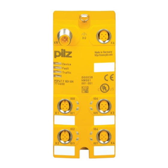
Page 8: Front View
Interface to X5 on the downstream module LEDs: – Device – Fault – Traffic – IO0 ... IO7 Scope of supply Decentralised input module PDP67 F 8DI ION/PDP67 F 8DI ION VA 4 blind plugs Operating Manual PDP67 F 8DI ION 1001643-EN-10... -
Page 9: Safety
Safety Intended use The products PDP67 F 8DI ION, PDP67 F 8DI ION VA are decentralised input modules de- signed for use in a rugged industrial environment up to protection type IP67. The module can be connected to a link module PNOZ ml2p or PNOZ mml2p from the con- figurable control system PNOZmulti. -
Page 10: Warranty And Liability
In safety-related applications, please comply with the mission time T in the safety-related characteristic data. When decommissioning, please comply with local regulations regarding the disposal of electronic devices (e.g. Electrical and Electronic Equipment Act). Operating Manual PDP67 F 8DI ION | 10 1001643-EN-10... -
Page 11: Function Description
Communication with the control system is via a safe data link. Data is exchanged cyclically. Diagnostics The status and error messages shown by the LEDs are saved in an error stack. The sys- tem software can read this error stack. Operating Manual PDP67 F 8DI ION | 11 1001643-EN-10... -
Page 12: Installation
Fit 2 x M4 internal threads on the mounting surface. Use two fixing screws to attach the product to the mounting plate. With shielded cables, connect the functional earth to the upper fixing screw X0. Dimensions Operating Manual PDP67 F 8DI ION | 12 1001643-EN-10... -
Page 13: Wiring
Please refer to the link module's operating manual for details of the maximum cable length. Pilz pre-assembled cable can be used to connect the inputs and outputs (see order refer- ence). We recommend you use pre-assembled Pilz connectors to connect the inputs and test pulse outputs (see order reference). -
Page 14: Connector Pin Assignment
2: CAN- A-coded 3: GND 4: CAN+ 5: Shield Interface to the Assignment next decentralised module: X6 5-pin M12 female 1: VCC connector 2: CAN- A-coded 3: GND 4: CAN+ 5: Shield Operating Manual PDP67 F 8DI ION | 14 1001643-EN-10... -
Page 15: Wiring Examples
– Wiring in accordance with the requirements of IEC 61076-2-101 and IEC 60204-1, clause 14.1.1 and 14.1.2 Single-channel, fail- safe input device 24 V Please ensure safety regulations and EMC guidelines are met! Operating Manual PDP67 F 8DI ION | 15 1001643-EN-10... -
Page 16: Example: Dual-Channel Input Devices, Without Test Pulses
Avoid short circuits by – Appropriate wiring – Wiring in accordance with the requirements of IEC 61076-2-101 and IEC 60204-1, clause 14.1.1 and 14.1.2 Operating Manual PDP67 F 8DI ION | 16 1001643-EN-10... -
Page 17: Example: Single-Channel, Failsafe Input Device, With Test Pulse
Please read the instructions provided with the input device. Only input devices with N/C contacts can be tested. Operating Manual PDP67 F 8DI ION | 17 1001643-EN-10... - Page 18 – Wiring in accordance with the requirements of IEC 61076-2-101 and IEC 60204-1, clause 14.1.1 and 14.1.2 Single-channel, fail- safe input device Test pulse T0 Please ensure safety regulations and EMC guidelines are met! Operating Manual PDP67 F 8DI ION | 18 1001643-EN-10...
-
Page 19: Example: Dual-Channel, Failsafe Input Device, With Test Pulse
Dual-channel input device with diverse channels Test pulse T1 Test pulse T0 Dual-channel input device with identical channels Test pulse T1 Test pulse T0 Please ensure safety regulations and EMC guidelines are met! Operating Manual PDP67 F 8DI ION | 19 1001643-EN-10... -
Page 20: Operation
Green Link module has detected a pulse error. Once the fault has been rectified, the decentralised input module will continue to work normally after a waiting period of just a few seconds. 0 signal is present Operating Manual PDP67 F 8DI ION | 20 1001643-EN-10... -
Page 21: Technical Details
24 VDC output, standard output, test pulse output test pulse output Rated voltage 24 V DC 24 V DC Typ. output current at "1" signal and rated voltage of semiconductor output 0,5 A 0,5 A Operating Manual PDP67 F 8DI ION | 21 1001643-EN-10... - Page 22 In accordance with the standard EN 60068-2-27 EN 60068-2-27 Number of shocks Acceleration Duration 16 ms 16 ms Airgap creepage In accordance with the standard IEC 60664-1 IEC 60664-1 Overvoltage category Pollution degree Operating Manual PDP67 F 8DI ION | 22 1001643-EN-10...
-
Page 23: Safety Characteristic Data
EN ISO 13849-1. The value also ap- plies as the retest interval in accordance with EN/IEC 61508-6 and EN/IEC 61511 and as the proof test interval and mission time in accordance with EN IEC 62061. Operating Manual PDP67 F 8DI ION | 23 1001643-EN-10... - Page 24 A safety function's SIL/PL values are not identical to the SIL/PL values of the units that are used and may be different. We recommend that you use the PAScal software tool to calculate the safety function's SIL/PL values. Operating Manual PDP67 F 8DI ION | 24 1001643-EN-10...
-
Page 25: Order Reference
380204 M12sm, 3m male con- male con- nector, angled nector, straight PSS67 Cable M8af M 4, 8-pin fe- M12, 4-pin 380205 M12sm, 5m male con- male con- nector, angled nector, straight Operating Manual PDP67 F 8DI ION | 25 1001643-EN-10... -
Page 26: Cable, M12 To M12
M12am, 10m male con- male con- nector, angled nector, angled PSS67 Cable M12af 30 m M12, 5-pin fe- M12, 5-pin 380215 M12am, 30m male con- male con- nector, angled nector, angled Operating Manual PDP67 F 8DI ION | 26 1001643-EN-10... -
Page 27: Adapter
5-pin M12 male 380325 PSENslock male connector connector PSEN op SL ad- Set of 2 ad- M12, 5-pin M12, 5-pin fe- 631187 apter apter cables for male connector male connector transmitter and receiver Operating Manual PDP67 F 8DI ION | 27 1001643-EN-10... -
Page 28: Ec Declaration Of Conformity
European Parliament and of the Council. The complete EC Declaration of Conformity is available on the Internet at www.pilz.com/downloads. Authorised representative: Norbert Fröhlich, Pilz GmbH & Co. KG, Felix-Wankel-Str. 2, 73760 Ostfildern, Germany Operating Manual PDP67 F 8DI ION... -
Page 29: Ukca-Declaration Of Conformity
2008. The complete UKCA Declaration of Conformity is available on the Internet at www.pilz.com/ downloads. Representative: Pilz Automation Technology, Pilz House, Little Colliers Field, Corby, Northamptonshire, NN18 8TJ United Kingdom, eMail: mail@pilz.co.uk Operating Manual PDP67 F 8DI ION | 29... - Page 30 We are represented internationally. Please refer to our homepage www.pilz.com for further details or contact our headquarters. Headquarters: Pilz GmbH & Co. KG, Felix-Wankel-Straße 2, 73760 Ostfildern, Germany Telephone: +49 711 3409-0, Telefax: +49 711 3409-133, E-Mail: info@pilz.com, Internet: www.pilz.com...
Need help?
Do you have a question about the PDP67 F 8DI ION and is the answer not in the manual?
Questions and answers