Pilz PNOZ mo4p Operating Manual
Expansion module for pnozmulti classic controllers
Hide thumbs
Also See for PNOZ mo4p:
- Configuration manual (359 pages) ,
- Operating instructions manual (16 pages)

Related Manuals for Pilz PNOZ mo4p


Summary of Contents for Pilz PNOZ mo4p
- Page 1 PNOZ mo4p Configurable, safe small controllers PNOZmulti Classic Operating Manual-20942-EN-08...
- Page 2 Preface This document is the original document. All rights to this documentation are reserved by Pilz GmbH & Co. KG. Copies may be made for the user's internal purposes. Suggestions and comments for improving this documenta- tion will be gratefully received.
-
Page 3: Table Of Contents
Dimensions in mm ........................Connecting the base unit and expansion modules ..............Commissioning ........................General wiring guidelines ......................Connection..........................Connection example ......................... Download modified project to the PNOZmulti system .............. Operation ..........................LED indicators .......................... Operating Manual PNOZ mo4p 20942-EN-08... - Page 4 Contents Function test of the relay outputs....................Technical details ........................Safety characteristic data ......................Supplementary data ......................Service life graph for the relay contacts..................Order reference ........................10.1 Product ............................. 10.2 Accessories ..........................Operating Manual PNOZ mo4p 20942-EN-08...
-
Page 5: Introduction
Introduction Introduction Validity of documentation This documentation is valid for the product PNOZ mo4p. It is valid until new documentation is published. This operating manual explains the function and operation, describes the installation and provides guidelines on how to connect the product. - Page 6 Introduction INFORMATION This gives advice on applications and provides information on special fea- tures. Operating Manual PNOZ mo4p 20942-EN-08...
-
Page 7: Overview
IEC 62061 Can be configured in the PNOZmulti Configurator Status indicators Max. 6 PNOZ mo4p units can be connected to the base unit Plug-in connection terminals: Either spring-loaded terminal or screw terminal available as an accessory (see Order ref- erences for accessories). -
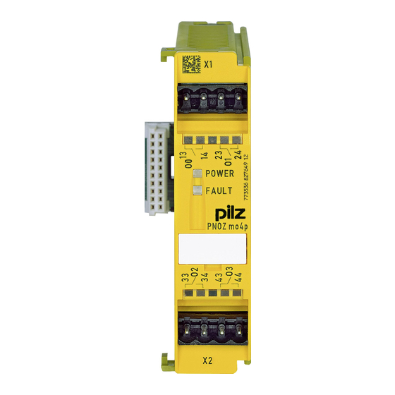
Page 8: Front View
Overview Front view Legend: O0 – O3 Relay outputs Operating Manual PNOZ mo4p 20942-EN-08... -
Page 9: Safety
(contactor or relay), which is controlled by a safe semiconductor output and is switched in series with both relay outputs. Alternatively the expansion module PNOZ mo5p can be used. The coated version of the product PNOZ mo4p is suitable for use where there are in- creased environmental requirements (see Technical details [ 20]). -
Page 10: Safety Regulations
(e.g. Electrical and Electronic Equipment Act). 3.3.5 For your safety The unit meets all the necessary conditions for safe operation. However, you should always ensure that the following safety requirements are met: Operating Manual PNOZ mo4p | 10 20942-EN-08... -
Page 11: Safety
Emergency stop equipment Safety circuits in accordance with VDE 0113 Part 1 and EN 60204-1 The module PNOZ mo4p may be used as a safety component in accordance with the Lifts Directive 95/16/EC and in accordance with the requirements of EN 81-20, EN 81-50 and EN 115-1. -
Page 12: Safety Regulations
This operating manual only describes the basic functions of the unit. The expanded func- tions are described in the PNOZmulti Configurator's online help. Only use these functions once you have read and understood the documentations. Operating Manual PNOZ mo4p | 12 20942-EN-08... - Page 13 Safety Do not open the housing or make any unauthorised modifications. Please make sure you shut down the supply voltage when performing maintenance work (e.g. exchanging contactors). Operating Manual PNOZ mo4p | 13 20942-EN-08...
-
Page 14: Function Description
System reaction time Calculation of the maximum reaction time between an input switching off and a linked out- put in the system switching off is described in the document "PNOZmulti System Expan- sion". Block diagram Operating Manual PNOZ mo4p | 14 20942-EN-08... -
Page 15: Installation
Electrostatic discharge can damage components. Ensure against discharge before touching the product, e.g. by touching an earthed, conductive sur- face or by wearing an earthed armband. Dimensions in mm 22,5 94 (3.70") (0.88") Operating Manual PNOZ mo4p | 15 20942-EN-08... -
Page 16: Connecting The Base Unit And Expansion Modules
Please refer to the document "PNOZmulti System Expansion" for details of the number of modules that can be connected to the base unit and the module types. Operating Manual PNOZ mo4p | 16 20942-EN-08... -
Page 17: Commissioning
13 (33) O0 (2) 14 (34) 23 (43) O1 (3) 24 (44) Feedback loop Redundant output Contacts from external contactors 13 (33) O0 (2) 14 (34) 23 (43) O1 (3) 24 (44) Operating Manual PNOZ mo4p | 17 20942-EN-08... -
Page 18: Connection Example
PNOZmulti Configurator and downloaded back into the base unit. Proceed as described in the operating manual for the base unit. NOTICE For the commissioning and after every user program change, you must check whether the safety devices are functioning correctly. Operating Manual PNOZ mo4p | 18 20942-EN-08... -
Page 19: Operation
Start the device again or open the safety contacts (switch off output), so that the internal diagnostics can check the correct opening of the safety contacts for SIL CL 3/PL e at least 1x per month for SIL CL 2/PL d at least 1x per year Operating Manual PNOZ mo4p | 19 20942-EN-08... -
Page 20: Technical Details
– Max. power – 480 W 24 V Safety contacts, DC 1 at – Max. current – Max. power – 48 W Utilisation category In accordance with the standard EN 60947-5-1 EN 60947-5-1 Operating Manual PNOZ mo4p | 20 20942-EN-08... - Page 21 -25 - 70 °C Climatic suitability In accordance with the standard EN 60068-2-30, EN 60068-2-78 EN 60068-2-30, EN 60068-2-78 Humidity 93 % r. h. at 40 °C 93 % r. h. at 40 °C Operating Manual PNOZ mo4p | 21 20942-EN-08...
- Page 22 27 mm 27 mm Material PPO UL 94 V0 PPO UL 94 V0 Bottom Front ABS UL 94 V0 ABS UL 94 V0 Connection type Spring-loaded terminal, screw Spring-loaded terminal, screw terminal terminal Operating Manual PNOZ mo4p | 22 20942-EN-08...
-
Page 23: Safety Characteristic Data
Cat. 1 2,90E-08 2,60E-03 2-channel PL e Cat. 4 SIL CL 3 3,00E-10 SIL 3 5,20E-07 All the units used within a safety function must be considered when calculating the safety characteristic data. Operating Manual PNOZ mo4p | 23 20942-EN-08... - Page 24 If the service life graphs are not accessible, the stated PFH value can be used irrespective of the switch frequency and the load, as the PFH value already considers the relay's B10d value as well as the failure rates of the other components. Operating Manual PNOZ mo4p | 24 20942-EN-08...
-
Page 25: Supplementary Data
The service life graphs indicate the number of cycles from which failures due to wear must be expected. The wear is mainly caused by the electrical load; the mechanical load is negli- gible. Switching current (A) Fig.: Service life graphs at 24 VDC and 230 VAC Operating Manual PNOZ mo4p | 25 20942-EN-08... - Page 26 With capacitive loads, any power surges that occur must be noted. With DC contact- ors, use flywheel diodes for spark suppression. We recommend you use semiconductor outputs to switch 24 VDC loads. Operating Manual PNOZ mo4p | 26 20942-EN-08...
-
Page 27: Order Reference
10.1 Product Product type Features Order No. PNOZ mo4p Expansion module, 2 or 4 relay outputs, positive-guided 773 536 PNOZ mo4p coated ver- Expansion module, 2 or 4 relay outputs, positive-guided, 773 537 sion coated version 10.2 Accessories Connection terminals... - Page 28 Front cover Support Technical support is available from Pilz round the clock. Americas Australia Scandinavia +45 74436332 Brazil +61 3 95600621 +55 11 97569-2804 Spain Canada Europe +34 938497433 +1 888-315-PILZ (315-7459) Austria Switzerland Mexico +43 1 7986263-0 +41 62 88979-30...
Need help?
Do you have a question about the PNOZ mo4p and is the answer not in the manual?
Questions and answers