
Subscribe to Our Youtube Channel
Related Manuals for Worth Data 7100 RF Terminal Series


Summary of Contents for Worth Data 7100 RF Terminal Series
- Page 1 ™ 7100 RF Terminal Portable Radio Frequency Terminal Worth Data ® 7100 Series Host Controlled RF Terminal System Owner’s Manual www.worthdata.com...
- Page 2 Shielded cables must be used with this equipment to comply with the relevant FCC regulations. Changes or modifications not expressly approved in writing by Worth Data may void the user's authority to operate this equipment. This device complies with Part 15 of the FCC Rules. Operation is subject to the following two conditions: (1) this device may not cause harmful inter- ference, and 2) this device must accept any interference received, including interference that may cause undesired operation.
-
Page 3: Table Of Contents
Table of Contents Introduction ........................................ 1 Differences ......................................1 Quick Start Guide ...................................... 2 Step 1: System Overview ..................................2 Step 2: Hardware Overview .................................. 2 Step 3: Connecting the RF Base to the Host Computer ........................2 Step 4: Installing Integrated Hardware Utilities ............................ 3 Step 5: Running Hardware Utilities .............................. - Page 4 Programming for the RF Terminal ..............................40 Base Station Error Feedback ................................47 Control Keys for Possible Programming............................. 49 ASCII Control Character and Extended ASCII Conversion (2D scanner only) .................. 50 Chapter 7: PromptCOM/ActiveX ................................51 Concepts - ActiveX Object Programming ............................51 PromptNET TCP/IP Active X Controls ..............................
-
Page 6: Introduction
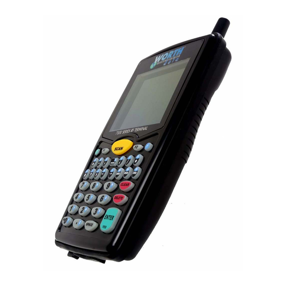
The 7100 RF Terminal is a low cost, easy-to-use radio frequency interactive terminal which communicates with PCs (or any computer) by RS-232 serial port, USB or Ethernet. This new terminal offers unprecedented power and ease of use, while maintaining compatibility with programs written for the older Worth Data Terminals. The list of fantastic features includes: ... -
Page 7: Quick Start Guide
Quick Start Guide This guide will give you a basic understanding of how the system functions and step through how to get the RF Terminal and RF Base up and running with a simple demo program. Step 1: System Overview The RF Terminal system consists of three main parts, the Terminal, the Base and the application program running on the host comput- er. -
Page 8: Step 4: Installing Integrated Hardware Utilities
Step 4: Installing Integrated Hardware Utilities The Utilities & Manuals CD that was included with your order includes the Integrated Hardware Utilities program. Simply insert the CD into the host computer and the setup program should run. If not navigate to the CD and run SETUP.EXE. A window should open (as shown below) with several choices of languages and programs to install. -
Page 9: Step 5: Running Hardware Utilities
Step 5: Running Hardware Utilities Once Integrated Hardware Utilities has completed installation you should find a program called “Hardware Utilities” in the startup menu. Go ahead and start Hardware Utilities. A window similar to the one shown below should open. Click on the button labeled “7000 RF Terminal”. - Page 10 The program will first hunt for the Base and when found it will launch the Test Program. If the Base cannot be found refer to the Base Installation Chapter for troubleshooting tips. The Test Program window should look like this: Now you can power up the RF Terminal and select option #1 to SIGN ON.
- Page 11 You can enter some data using the RF Terminal keypad like “555” and press enter or scan a bar code. The entered or scanned data should appear in the status window as shown below. You are now up and running. You can continue to enter data or scan bar codes and observe the transactions in the status window. This demo gives you a basic idea of how the RF Terminal system works.
-
Page 12: Chapter 1: Installation
Chapter 1: Installation Components The components in your RF Terminal system will vary according to the configuration of your system. Your RF Terminal ship- ment should contain at least: An RF Terminal LT71XXX. C25 Micro USB Cable – for programming and voice prompt upload. ... -
Page 13: Overview
When connected for the first time most computers will automatically find and load the virtual com port driver. If the driver is not found automatically it can be downloaded from the Worth Data website (www.barcodehq.com). Drivers are available for most versions of Windows from XP to present, Linux and Mac OS X. - Page 14 Once installed, the host program will be able to communicate with the B5021 anywhere on the network. The CPR Manager program is included on the B5021 CD or can be downloaded from the Worth Data website. After installation the CPR Man- ager program will be located in the Lantronix folder of the Start Menu.
-
Page 15: Rf Terminal Operation
120 or Pentax D-LI7. We use a high quality Japanese Li-Ion cell in our OEM pack that we supply with the RF Terminal. You can obtain a replacement from Worth Data (P/N: L02) . Our pack is rated at 1950 mAh and provides the longest runtime available. Do not use a battery pack of unknown quality or origin. -
Page 16: Recharging The Rf Terminal Battery
To change the internal battery: Turn OFF the RF Terminal. Remove the battery holder door on the back of the RF Terminal by removing the two screws holding the door in place.. Remove the old battery and insert a new one, making sure to orient the battery with the battery contacts facing the bat- tery connector. - Page 17 RF Terminal Menu Functions Upon power-up, the RF Terminal displays the following opening screen: (The opening screen can be bypassed upon power up. See Chapter 2) On second line on the screen, FIRMWARE: Uxxx, gives the firmware revision number. The letter U indicates USA frequency. Rzz refers to the version of the radio processor firmware.
-
Page 18: Installing The Integrated Hardware Utilities Software
Installing the Integrated Hardware Utilities Software The RF Terminal system ships with a CD of programs for use with the RF Terminal and Base station. You have the choice of installing the following: Windows Demo Programs and RF DLL Programmers Library ... -
Page 19: Chapter 2: Rf Terminal Setup
Chapter 2: RF Terminal Setup The RF Terminal can be configured using the Terminal Setup Menu. Most users do not need to change anything in the setup. The most commonly changed setup parameters are the Terminal ID (especially if you have more than 1 terminal) and the Channel (if you are adding an additional Base station). -
Page 20: Using The Setup Menu On The Rf Terminal
Using the Setup Menu on the RF Terminal The RF Terminal can be setup via the Terminals' keypad by entering Setup Mode from the main menu. Press the On/Off key. You should now see the MAIN MENU message: Press the 2 key. The next menu allows you to choose which item to configure: RF TERMINAL SETUP RF CONFIGURATION - - - - - - - - - 1 BAR CODE OPTIONS - - - - - - - - - 2... - Page 21 RF Configuration Default settings are shown in bold type. The RF Terminal will typically require no setup changes except, Terminal ID (if more than one terminal) and enabling bar codes to be read other than UPC or Code 39. RF Terminal ID Default ID Available IDs 0-9, A-Z, a-z, - =...
- Page 22 Control Keys Only Control Keys Only Control Keys Only Several special keys on the RF Terminal keypad can generate a response automatically, sending a separate message to the host by simply pressing the appropriate control key (without pressing the ENTER key afterward). This allows for simple and fast scrolling by the operator.
-
Page 23: Bar Code Options
Bar Code Options Code 3 of 9 (Code 39) Code 3 of 9 Full ASCII Accumulate Mode Transmit Start Stop MOD 43 Check Digit Transmit MOD 43 Caps Lock Decode Option 0, 1, 2 The Start and Stop character for Code 39 is the * character. Setting 4 determines whether or not those characters are transmitted to the computer along with the data. - Page 24 ble transmission of the ISBN format, set option 7 to ON. To return to the default of normal EAN-13 transmission, set option 7 to OFF. For details on ISBN, see Appendix J, UPC/EAN. UPC-A can be transmitted in EAN-13 format by adding a leading 0 (USA county code) to the UPC-A data. To transmit in EAN-13 format, set option 8 to ON.
- Page 25 2 of 5 Code Interleaved 2 of 5 Check Digit Transmit Check Digit Standard 2 of 5 2 of 5 Code Length Setting 2 requires that the last digit in your bar code conform to the specifications for the 2 of 5 check digit calculation. See Ap- pendix I;...
- Page 26 DataBar / RSS-14 plus UCC-128 Format By default, DataBar / RSS-14 is disabled. Press the 1 key to toggle through the DataBar / RSS-14 options listed above. We support the standard and stacked version of DataBar / RSS-14. For more information on GS1 DataBar, see the GS1.org website at http://www.gs1.org/productssolutions/barcodes/databar/ Other Bar Code Options Storage Tek Label...
-
Page 27: Bluetooth Settings
Bluetooth Settings: Note: The Bluetooth options will only appear on LT71x2x models. RF Terminals with Bluetooth have 2 options added to the main menu that allow the LT71x2x to pair with other Bluetooth devices. Currently only the Serial Port Profile (SPP) is supported. This is the most common profile for serial cable replacement and is typically used for Bluetooth enabled printers. -
Page 28: Speaker Settings
Speaker Settings Speaker Options Beep Volume Medium High The default volume of the “Beep” is Medium. Each time you press the “1” key you will hear a beep at the different vol- ume settings. When you are happy with the loudness of the beep tone, press 0 or F1 to exit. Beep Tone 1 - Lowest 2 - Low... -
Page 29: Lcd Options
4.5-second laser beam increases the amount of time the laser beam is activated, giving the laser more time to try and read a code. This option is useful for trying to read poor quality code. The default beam time is 2 seconds. Aiming Dot Duration 00 –... -
Page 30: Other Settings
timeout. Dimming the display helps extend battery life. The default is 05 for 5 seconds. A setting of 00 will disable the timeout and keep the display always at the standard brightness level. Other Settings Preamble Preambles are user-defined data that is attached to the beginning of data (bar code or keyed) that is transmitted to the host by the RF Terminal. - Page 31 By default, the RF Terminal has no Postambles configured. Postambles can contain up to 15 characters. To set a Postamble: Select option “8” from the RF Terminal Setup menu then “2” for Postamble from the Other Settings menu. ...
-
Page 32: System Tools
The Encryption Key on the Base is set using the Worth Data Hardware Utilities program that is included on the CD that came with the Base or can be downloaded from the Worth Data website. Start by connecting the Base to a PC then run the Hardware Utilities on the PC that is connected to the Base. -
Page 33: Chapter 3: Base (B5011) And Relay Setup
USB port, or one of the computer COM ports using the 9 pin serial cable (F36), or 25 pin serial cable (F34) included with your system and that the power supply (5v from Worth Data ONLY) is plugged in – a power supply is not needed with the C21 USB cable connection. - Page 34 Terminals are in use, and go to Site Test mode on the Terminal. You should get 90-100% on first try. If you don’t, it’s a good chance your radios need repair. Call Worth Data for an RMA.
-
Page 35: Chapter 3A: Ethernet Base (B5021) Setup
Once installed, the host program will be able to communicate with the B5021 anywhere on the network. The CPR Manager program is included on the B5021 CD or can be downloaded from the Worth Data website. After installation the CPR Man- ager program will be located in the Lantronix folder of the Start Menu. -
Page 36: Chapter 4: Operational Theory
A little more in depth… This RF system’s dialogue is Terminal initiated. The Terminal says, “I’m here, give me something to do. The Worth Data RF sys- tem is different from other systems in that our RF Terminal does not constantly “listen” for a data prompt from the host. We de- cided to use a different approach that would help to eliminate unnecessary radio traffic, conserve battery power, reduce the size of the Terminal, and greatly simplify the operation. -
Page 37: How The One-Way Rf System Works
Lets suppose that a RF Terminal and a Base Station have been processing data by sending prompts and data back and forth as de- scribed in example 1. The Base Station sends a data prompt to the RF Terminal, the RF Terminal transmits the operator-entered data back to the Base Station. -
Page 38: How Site Survey Works
One-Way mode also works well as a test program since it doesn’t require a program running on the host computer or even that the Base Station be connected to the host. To get into One-Way Mode select option 3 from the opening screen menu. If the Base Station already has other RF Terminals signed on in Two-Way mode, you will not be allowed into the system. -
Page 39: Chapter 5: Performance Issues
Chapter 5: Performance Issues Evaluating your area of planned operation Since every operational environment is different, it is impossible for us to tell you exactly what equipment you need and where you should put it to achieve maximum performance from your RF System. However with 3.3 miles of open area range, unless you are going through a lot of walls, you probably won't care where the Base is located and you probably will not need a Relay. -
Page 40: Relay Stations
If the Base Station is powered up, walk to the area where you want to perform your first test (start at 50 ft. or greater). When in position, stop and look at the RF Terminal display. It should read: Press Enter When Ready or F1 to Exit Press the ENTER key to start the test. - Page 41 Once the RF Terminal is Relay-ready, it can use the Relay instead of the Base Station to communicate. If a RF Terminal tries to transmit 10 times to a Base Station without a response, it broadcasts a “who can hear me” message. If both the Base Station and the Relay hear the message, whoever answers back to the RF Terminal first becomes the point of contact for that RF Terminal.
- Page 42 erage. Alternatively, locating the Base Station and Relay as shown below results in better coverage: To Site Survey a Relay, all other Relays and Base Stations must be turned off. This is the only way to know for sure which Relay is responding.
-
Page 43: Chapter 6: Programming
Chapter 6: Programming Before you begin programming… The RF Terminal operates in two basic ways: One-Way communication, where all data transfer is initiated by the RF Terminal. This is not very useful, because it has no edit- ing or prompting. The Base Station itself simply acknowledges the receipt of the data by echoing it back to the Terminal. The host computer has no dialog whatsoever with the Base Station or Terminal;... -
Page 44: Failure Planning
Failure Planning Hardware Failures Let’s assume that each part of the system has failed. How are you going to know what has happened and how are you going to re- cover? The most frequent failures are at the Terminal level. If a Terminal has a hardware failure, it will not be able to SIGN OUT. It is possible for the Terminal operator to press the ON/OFF key or the F1 key by accident, forcing the Terminal to SIGN OUT - sometimes in the middle of a transaction. -
Page 45: Programming For The Rf Terminal
Programming for the RF Terminal The three levels of programming support offered for the RF Terminal are: Low Level ASCII sequences sent to and from the Base Station by the user program reading/writing to the serial port. Active X drop-in components. Every necessary function is defined. You just complete the code for each function. ... - Page 46 Here is a listing of valid commands and examples: Command charac- Command function ters Reinitializes all terminals Reinitializes Terminal #3 1@Bn Make Terminal #1 beep n (1-9) times 2@C0 Clears the entire screen (4, 6 or 15 lines) on Terminal #2. *See more about 4 and 6 line displays on page 6-4.
- Page 47 Color Display Programming New commands have been added to take advantage of the larger color display on the LT7001. You now have the ability to define the color and font size on a line by line basis. There are 16 possible text and background colors available to choose from. They are the same 16 colors used in HTML programming. The @C command has been expanded to set the foreground and background colors for the entire display and within the same com- mand you can also set the font size for the entire display to all be the same or split up the display using different size fonts for each line.
- Page 48 Here are some more examples: @C\E1 will clear the screen and set the default colors to WHITE text on a BLACK background. In concept, @C\E1 is the same as @C0\E1; however, @C0\E1 is an invalid command. The change of user colors is always embedded in a Clear Screen Command. @CS1M3L1S1L2\BE will clear the screen and set the first line to be small font, the next 3 lines to be medium font, the next line to be large font, the next line to be small font and the last two lines to be large font with RED text on a WHITE background for all lines.
- Page 49 For example, the command @1,1,1, Enter Quantity would display Enter Quantity starting at position 1 on line 1, then wait for the operator to enter their data. These are valid entries for the third position character: No data input for this Command, Display ONLY Data input required from the keypad or scanner Only keypad input allowed, start un-shifted Only keypad input allowed, start SHIFTED...
- Page 50 first part, wait for the acknowledgement (ID CR), and then send the remaining part. If you are using the @S command with a printer other than the Zebra Cameo or QL3, you may have to change the Protocol parameter in the RF Terminal to XON/XOFF.
- Page 51 The SIGN ON character for a 6 line display RF Terminal operating in 6 line display mode (see the previous point concerning LCD DISPLAY MODE) is different than for a 4 line display. A 6 line display terminal operating in 6 line mode signs on using ASCII 22.
-
Page 52: Base Station Error Feedback
SIGN ON To login to the host computer, the user presses a key on the RF Terminal at power-up to get to the SIGN ON screen. As the user SIGNs ON, the Base Station sends back the following SIGN ON message to the host: Byte position Function Possible values... - Page 53 Byte position Function Possible values RF Terminal ID 0-9, A-Z, a-z, - = Terminal NOT Signed In DC1(ASCII 17) Last Termination of message CR (ASCII 13) The ASCII 17 character can be changed to ASCII 16 for XON/XOFF sensitive systems by changing the Base Station Setup. See Chapter 2;...
-
Page 54: Control Keys For Possible Programming
Base Shut Down Due to Host Logic Error You can re-initialize the terminal by sending *@EOT or by powering the base off and back on. Automatic Check Back When a terminal checks back in to see if there is a change in instructions, the host can send back the same prompt or send back a new prompt. -
Page 55: Ascii Control Character And Extended Ascii Conversion (2D Scanner Only)
cial program functions, such as scrolling through data, backing up steps, jumping, finishing a process, etc. The keys are as follows: Code transmitted to Host UP ARROW key FS (ASCII 28) DOWN ARROW key GS (ASCII 29) LEFT ARROW key RS (ASCII 30) RIGHT ARROW key US (ASCII 31) -
Page 56: Chapter 7: Promptcom/Activex
Chapter 7: PromptCOM/ActiveX Drop-in components are tools that are added to your programming environment "tool kit". There are a variety of different tech- nologies around for implementing a drop-in component such as VBX (for Visual Basic) and VCL (for Delphi and C Builder) and COM (ActiveX). - Page 57 The details of how to access Properties/Methods/Events varies between development platforms. Details of how it works in some of the most popular platforms is illustrated in the samples included with the RF Utilities CD or available for download from our website at: http://www.barcodehq.com/downloads.html Properties –...
- Page 58 Color Codes for 7000 (15-line) Terminal aqua 1 - black blue fuchsia gray green lime maroon navy olive 10 - purple 11 - 12 - silver 13 - teal 14 - white (white) 15 - yellow OpenDevice Function: Opens the communications (serial) port. This must be called before any of the methods described below. Make sure to set all Properties as desired before calling this method (except ActiveTerminal Quiet...
- Page 59 InputKeyBd Parameters: line, position, prompt, shifted, timestamped InputKeyBdColor (15-line terminal only) Parameters: line, position, prompt, shifted, timestamped,FG,BG Function: This instructs the to display the prompt at line and position and wait for data to be en- ActiveTerminal tered from the terminal keypad only. If shifted is set to “true”, the terminal will start in shifted mode. Timestamped appends a (hhmmss) prefix to the returned data.
- Page 60 Function: This instructs the to display the prompt at line and position. Must be followed by an " ActiveTerminal " method call to take effect. ClearScreen Function: This instructs the to clear its display. Must be followed by an " "...
- Page 61 ReInitAll Function: Instructs all attached terminals to re-initialize. GetErrCode Returns code for the most recent error. Calling this method resets the Error Code to 0. Error Codes 0. No Error 1. Command Data Too Long 2. Error on Close Device 3.
-
Page 62: Promptnet Tcp/Ip Active X Controls
Data passed: terminal Event: The one-for-one host prompt/terminal response protocol has been violated. The host cannot send a second In- put command until it has received a response from the first command. If a base station receives 5 se- Input quence errors in a row, a Host Logic error is generated and the base shuts itself down. -
Page 63: Programming Considerations
Programming Considerations Network Setup The network settings on both client and server must support TCP/IP communications. It is critical that the client and server computers are "visible" to each other across your network. Both computers must have an IP address in the same subnet. The server requires a static IP address while the Client can either have a static address or use an as- signed IP address via a DHCP server or equivalent. -
Page 64: Concepts - Tcp/Ip Com
Concepts - TCP/IP COM Drop-in components are tools that are added to your programming environment "tool kit". Only the ActiveX variety are widely compatible with almost all development environments. When you use drop-in components in your program you will follow the standard object-oriented programming paradigm that uses properties, methods, and events to implement the functionality of the drop-in component. - Page 65 Parameters: basename, channel, terminal, line, position, prompt, shifted, timestamped Function: This instructs the terminal attached to client basename on channel to display the prompt at line and posi- tion and wait for data to be entered from the terminal keypad only. If shifted is set to "true", the terminal will start in shifted mode.
- Page 66 Function: This instructs the terminal attached to client basename on channel to play voice message number msgnum. Msgnum may be a value from 1 to 99. Must be followed by an " " method call to take ef- Input fect. ReInit Parameters: basename, channel, terminal...
- Page 67 Data passed: basename, channel, terminal Event: The one-for-one host prompt/terminal response protocol has been violated. The host cannot send a second Input command until it has received a response from the first command. If a base station receives 5 sequence er- Input rors in a row, a Host Logic error is generated and the base shuts itself down.
-
Page 68: Chapter 8: Portable Printers
Chapter 8: Portable Printers Portable Printing - Common Information The LT7102, LT7102H, LT7112, & LT7112H Models come equipped with Bluetooth Wireless Technology, allowing you to wirelessly connect to a portable printer to print labels, receipts, price tags, or scan magstripe cards.. Keep in mind the following information when using these versatile printers: ... - Page 69 So, when the RF Terminal transmits the data to the host, it will be in the following format: RF Terminal ID + T1: DATA + CR RF Terminal ID + T2: DATA + CR RF Terminal ID + T1: DATA + T2: DATA + CR For further information, see your Printing Systems Programming Manual on the CD ROM shipped with the printer.
-
Page 70: Chapter 9: Voice Message Operations
Chapter 9: Voice Message Operations The RF Terminal’s exclusive use of voice prompts allows you to overcome problems such as literacy, language and lighting. With proper planning, voice prompting can enhance your RF Terminal application, making it faster and simpler. Voice messages are rec- orded (or imported from existing sound files) and uploaded to the RF Terminal using the Hardware Utilities program included on the Utility CD. - Page 71 Don't be discouraged if your first attempts at recording Voice Prompts don't sound very good. Again, practice speaking clearly and calmly, and you'll soon get the hang of it. Be sure to record error messages for all possible problems that the user may encounter during a session. Once the op- erator becomes accustomed to listening to the voice prompts, it may become easy to overlook a “display only”...
-
Page 72: Chapter 10: Troubleshooting
Chapter 10: Troubleshooting General Considerations Site Test The most basic tool for troubleshooting is the Site Test at 50 feet range. (See Chapter 4 for the details on how to do a Site Test). If the Site Test fails at close range (50 feet), you have found the problem. The radio on either the Base Station or the RF Terminal is defective. -
Page 73: Terminal Error Messages
Terminal Error Messages Meaning – Action Required Message Meaning – Action Required Message Relay n Cannot be The terminal has established contact with “Waiting for Base to This is a normal message, generated when you Heard by the Base Relay Station x. Relay Station x has at- Acknowledge...?”... -
Page 74: Troubleshooting Specific Problems
Terminals are in use, and go to Site Test mode on the Terminal. You should get 96-100% on first try at greater than 10 feet. If you don’t, it’s a good chance your radios need repair. Call Worth Data for an RMA. -
Page 75: Rf Terminal Problems
Charge your Terminal for at least an hour and try again. I get 6 beeps when the RF Terminal powers up... The unit needs repair. Call Worth Data for an RMA. Problems reading Bar Codes The reader won't beep when I try to read bar codes... -
Page 76: Problems With Voice Prompts
If you cannot find the answer here, or if doing a diagnostic reset does not help, call your Dealer or Worth Data for help. Save the shipping box. If you ever need to send the RF Terminal or any of its parts back for repair, use this box. -
Page 77: Chapter 11: Firmware Upgrades
Chapter 11: Firmware Upgrades Updates are occasionally available for the RF Terminal System when new features or improvements are added. RF Terminal Firmware Upgrades The RF Terminal firmware can be upgraded by downloading new firmware into the RF Terminal from your computer. Normal Firmware Download for a Terminal The RF Terminal firmware can also be upgraded by downloading a file with the current firmware into the RF Terminal's flash EPROM using the Hardware Utilities program found on the RF Terminal Utilities CD. -
Page 78: Chapter 12: Base Station Configuration
Chapter 12: Base Station Configuration Opening a Base As preparation for changing the Channel on a Base Station or changing the Base to operate as a Relay, the case must be opened to expose the circuit board with the switches and jumpers. Be sure you disconnect power before opening the case. Turn your Base Station upside-down, and unscrew its single phillips head screw. -
Page 79: Adding Relays
Changing the Channel on a Base/Relay The Base Station and its related Relays must have their channel set to the same channel as the RF Terminals in their network. The channel is set on a Base or Relay by turning a rotary switch to the setting 0-5 (6 different channels to choose from). Use a very small flat head screwdriver to turn the switch to the desired number. - Page 80 Routing the Wiring The below diagram illustrates the RIGHT way to route your wiring and which units should be terminated. Notice this is the clas- sical bus interface where the Base and Relays are connected to a “one-cable bus”. The bottom of the Y-Cables is connected into the unterminated base or relay(s).
- Page 81 Make a cable with 5-5, 6-6, 2-2, and 3-3 (a straight cable); but, be careful that you select wires so that the 2 wire is in the twisted pair with the 3 wire, and the 5 wire is in the twisted pair with the 6 wire. Do not use pre-terminated Ethernet cables since the pairing is different.
-
Page 82: Base Station Cable Choice
Setting the Relay ID If you only have one relay, there is no need to set the Relay ID which is shipped default as relay 1. If you need to change it or you have multiple relays, it must be changed using the RF 7000 Base Serial Configuration Utility. RS-422 Termination When adding Relays to a system, the last Relay(s) in the line(s) must be terminated. -
Page 83: Relay Station Rs422 Pin-Outs
Mod 8 RJ45 Function DB 9 Female Shell (chassis ground) Shell Transmit Data Receive Data Signal Ground F36 9 pin cable If you plan on building your own extension cables, you must use well shielded cable and you cannot use twisted-pair cable. You can order custom length RS-232 extension cables from Global Computer Supplies - phone 800-845-6225, part number ZCC4912X. -
Page 84: Appendix A: Bar Code Specifications
Appendix A: Bar Code Specifications Code 39 Specifications Code 39 (or Code 3 of 9) is the de facto standard of non-retail American industry. It is widely used in the automotive industry (AIAG specifications) as well as in government and military applications (LOGMARS specifications). Code 39 is flexible, fea- tures a large character set, variable data length and density, and bi-directional readability. - Page 85 Divide the sum by 43: (thus the name modulus 43) 108/43 = 2 with a Remainder of 22 Find the character corresponding with the remainder. M (value 22) is the CHECK CHARACTER The data becomes 123XYZM, with M added as the Mod-43 check character. Full ASCII Extension to Code 39 "Full-ASCII Code 39"...
-
Page 86: Code 93 Specifications
Accumulate Mode must be turned on using the bar coded Setup Menu or by using the keypad. Accumulate Mode is located in the Code 39 parameters. Choose 4 to Enable or 5 to Disable this feature. This numeric Code 39 "Barpad" illustrates ACCUMULATE Mode. Scan 5, 3, 8, and Enter. The RF Terminal transmits a single message of “538”. -
Page 87: Code 128 Specifications
Codabar start/stop transmission The Codabar section on the RF Terminal Setup Menu lets you determine whether Codabar start/stop characters are transmitted or not. If you are varying start/stop characters with different types of labels, you'll want to "Enable Stop/Start character Trans- mission". - Page 88 Start C not transmitted Function Code 1 transmitted 2 Digit Qualifier transmitted 7 Digit Data Portion transmitted 1 Digit Mod 10 Check Digit* transmitted- 1 Digit Modulus 103 not transmitted Stop Code not transmitted *Calculated using 19digits-UPC method The UCC 128 specification is used extensively by the retail industry. If you have a requirement for a UCC 128 Serial Shipping Container bar code, be sure to follow the specification as closely as possible as many vendors will impose fines for non- conformance.
-
Page 89: Interleaved 2 Of 5 Code Specifications
Terminal to check each field for the proper length. Use a check digit. Worth Data's LabelRIGHT printing program automatically calculates and prints a check digit upon request using the method below: Interleaved 2 of 5 Mod 10 check digit calculation ... -
Page 90: Upc / Ean Specifications - Gs1-12, Gs1-13
UPC / EAN Specifications – GS1-12, GS1-13 UPC GS1-12 symbols are found on almost all grocery products and many other retail items. The UPC code most people are familiar with (UPC-A) is a fixed-length (12 digits) numeric only code, with the first digit controlled by UPC coding assignments and the last digit a checksum. - Page 91 ISBN Specifications ISBN (International Standard Book Numbering) bar codes are essentially EAN-13 with a 5 digit supplement, where the first 3 digits are the Bookland country codes of 978 for books and 977 for periodicals. Although the bar code contains 18 characters, the ISBN format uses only 9 of them, along with a newly calculated Mod-11 check digit.
-
Page 92: The Upc/Ean Checksum Character
The last character in a UPC-A, UPC-E, UPC-E1, EAN-13 or EAN-8 bar code is the checksum. For reference, these are the meth- ods of calculation: Checksum calculation for UPC-A, EAN-13 and EAN-8 Use Worth Data's phone number (it's not a real UPC-A code) as sample data: 18314589938 Assign even and odd positions, starting at the right and moving left:... -
Page 93: Msi/Plessey Specifications
MSI/Plessey Specifications Plessey is a variable length numeric only bar code. MSI Bar Code is a variable length, numeric-only code with an automatically appended Modulus 10 check digit. MSI is sometimes called Modified Plessey Code. If the user specifies an additional check digit, the MSI code can be 14 digits long, otherwise it has a maximum length of 13 characters. -
Page 94: Appendix B: How To Scan A Bar Code
Appendix B: How to scan a bar code The 7100 RF Terminals include a built in bar code scanner depending on the model. This section will include information on dif- ferent scanners as well as how to use each one. Laser Scanners If you are using a laser scanner, technique is not critical. -
Page 95: Ascii Code Equivalent Table
ASCII Code Equivalent Table The 128 ASCII codes, their 3-digit decimal equivalents and 2-digit hex equivalents are detailed in the below table. 3 digit 3 digit 3 digit 3 digit char ASCII char ASCII char ASCII char ASCII ‘ " &...
Need help?
Do you have a question about the 7100 RF Terminal Series and is the answer not in the manual?
Questions and answers