Bradley Express SS Series Installation Instructions Manual
Lavatory system
Hide thumbs
Also See for Express SS Series:
- Installation manual (27 pages) ,
- Installation instructions manual (17 pages) ,
- Installation instructions manual (17 pages)
Table of Contents
Advertisement
Quick Links
IMPORTANT
Read this entire installation manual
to ensure proper installation, then
file these instructions with the
owner or maintenance department.
Flush all the water supply lines
before making connections.
Wall anchors used must have a
minimum pull-out rating of 1,000
lbs.
Product warranties may be found
under "Product Information" on our
web site at www.bradleycorp.com.
215-1241 Rev. E; EN 03-813
© 2004 Bradley Corporation
Page 1 of 17
5/11/04
Installation
Instructions
For Service Only
SS-3/IR/WH97
Express® Lavatory
System SS-Series
Express® Lavatory Systems are
ADA compliant.
Table of Contents
Pre-Installation Information . . . . . . . . . . . . . . . .2
Dimensions . . . . . . . . . . . . . . . . . . . . . . . . . . . . .3
Installation Instructions . . . . . . . . . . . . . . . . . 4-9
Cleaning and Maintenance . . . . . . . . . . . . . . . .10
Soap Dispenser Maintenance . . . . . . . . . . .11-12
Wiring Diagram . . . . . . . . . . . . . . . . . . . . . . . .12
Assembly of Components . . . . . . . . . . . . . .13-14
Check Valve Troubleshooting . . . . . . . . . . . . . .15
Solenoid Troubleshooting . . . . . . . . . . . . . .15-16
Vernatherm™ Mixing Valve . . . . . . . . . . . . . . .17
P.O. Box 309, Menomonee Falls, WI 53052-0309
TEL. 1-800-BRADLEY
http://www.bradleycorp.com
FAX 262-251-5817
Advertisement
Table of Contents

Related Manuals for Bradley Express SS Series


Summary of Contents for Bradley Express SS Series
-
Page 1: Table Of Contents
Product warranties may be found under "Product Information" on our web site at www.bradleycorp.com. P.O. Box 309, Menomonee Falls, WI 53052-0309 215-1241 Rev. E; EN 03-813 TEL. 1-800-BRADLEY FAX 262-251-5817 © 2004 Bradley Corporation http://www.bradleycorp.com Page 1 of 17 5/11/04... -
Page 2: Pre-Installation Information
• (10) 3/8" wall anchors, bolts and washers to mount frame and bowl to wall (minimum pull-out rating of 1,000 lbs.) • 1/2" NPT tempered supply piping • 1-1/2" NPT drain piping • 110 volt electrical outlet for 110/24 VAC plug-in transformer (supplied) 5/11/04 Bradley Corporation • 215-1241 Rev. E; EN 03-813... -
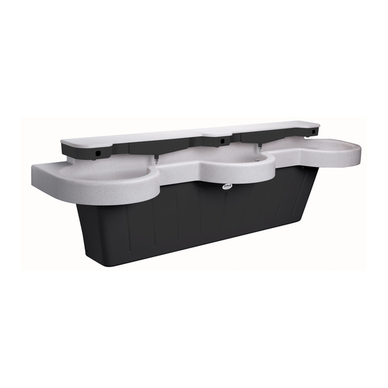
Page 3: Dimensions
Express® Lavatory System SS-Series Installation Instructions - For Service Only SS-3/IR/WH97 Dimensions (Standard Height Mounting - SS-3/IR/WH97 Express® Lav System) Bradley Corporation • 215-1241 Rev. E; EN 03-813 5/11/04... -
Page 4: Installation Instructions
4. Install (10) 3/8" wall anchors with a minimum pull-out rating of 1,000 lbs. (supplied by installer) at the locations shown in Figure 1 below (or Figure 1a on page 5). Standard Height Mounting SS-3/IRWH97 Express® Lavatory System Figure 1 5/11/04 Bradley Corporation • 215-1241 Rev. E; EN 03-813... - Page 5 Express® Lavatory System SS-Series Installation Instructions - For Service Only SS-3/IR/WH97 Juvenile Height Mounting SS-3/IR/WH97 Express® Lavatory System Figure 1a Figure 2 Bradley Corporation • 215-1241 Rev. E; EN 03-813 5/11/04...
- Page 6 3/8" bolts and washers to mount the frame to the wall (see Figure 4). Installation Instructions continue... FRAME (9) TORX-HEAD SCREW PANEL Figure 3 FRAME (6) 3/8" BOLTS AND WASHERS Figure 4 5/11/04 Bradley Corporation • 215-1241 Rev. E; EN 03-813...
- Page 7 4. Tighten the screws installed in procedure #2 above to secure the bowl assembly to the frame. Do not overtighten. Installation Instructions continue... BACK VIEW Figure 5 Bradley Corporation • 215-1241 Rev. E; EN 03-813 5/11/04...
- Page 8 THERMOSTATIC MIXING VALVE FLEXIBLE SUPPLY HOSE CONNECT TO CONNECT TO 1/2" NPT COLD 1/2" NPT HOT WATER SUPPLY WATER SUPPLY FLEXIBLE SUPPLY HOSE TO SUPPLY LINE (TO SOLENOID BRACKET) Figure 6b 5/11/04 Bradley Corporation • 215-1241 Rev. E; EN 03-813...
- Page 9 (FROM SPRAYHEAD) SPRAYHEAD COMPRESSION CONNECTOR TO TRANSFORMER SUPPLY HOSE TO VALVE WHITE JUMPER TERMINAL BLACK SPADE RED SPADE TERMINAL TERMINAL WHITE JUMPER WHITE JUMPER GREEN SPADE TERMINAL Figure 7 TERMINAL TERMINAL Bradley Corporation • 215-1241 Rev. E; EN 03-813 5/11/04...
-
Page 10: Cleaning And Maintenance
Brite pad or with an abrasive cleaner. • Repair kit: In the unlikely event your Terreon® surface becomes damaged, it can easily and inexpensively be repaired. Contact your Bradley representative to order a repair kit and be sure to specify color when ordering. -
Page 11: Soap Dispenser Maintenance
4. After each soap tank is filled, position the soap tanks into the sprayhead openings and push into place. Figure 7a (2) ACTIVATION LABEL 204-476 (one above each activation zone) FILLER HOLE SOAP TANK 133-107 (GRAY) 133-131 (PUTTY) 133-131A (COAL) (2) SOAP DISPENSER VALVE Figure 7b S09-007 Bradley Corporation • 215-1241 Rev. E; EN 03-813 5/11/04... -
Page 12: Wiring Diagram
Then remove the chain and rinse out the soap tank. Clean internal components: To clean the internal components of the soap dispenser, pump hot water through the soap dispenser until a clean flow of water comes out of the valve. 5/11/04 Bradley Corporation • 215-1241 Rev. E; EN 03-813... -
Page 13: Assembly Of Components
Vernatherm™ Thermostatic Mixing Valve Assembly S67-571 Optional Stop/Strainer/Check Valve VERNATHERM VALVE (S01-116B) 90° ELBOW 169-639 FLEX HOSE WITH SWIVEL END FILTER 269-653 WASHER BRASS PIPE 269-1188 STOP/STRAINER/CHECK VALVE NIPPLE S60-003 113-006DJ STOP/CHECK VALVE S27-102 Bradley Corporation • 215-1241 Rev. E; EN 03-813 5/11/04... - Page 14 SCREW 160-120 1/4" ELBOW 110-115 145-090 AERATOR HOUSING 115-133 INFRARED WINDOW 269-1241 O-RING 125-001CK DIFFUSER 269-508 STREAMFORMER 115-125 SCREW 160-289 Drain Assembly Other replacement parts 5/11/04 Bradley Corporation • 215-1241 Rev. E; EN 03-813...
-
Page 15: Check Valve Troubleshooting
• reconnect to the adjacent valve and turn on electrical and water supplies to the unit; • pass your hand in front of the sensor. If the station still fails to turn on, replace the sensor (see page 14). Bradley Corporation • 215-1241 Rev. E; EN 03-813 5/11/04... - Page 16 Express® Lavatory System SS-Series SS-3/IR/WH97 Installation Instructions - For Service Only 5/11/04 Bradley Corporation • 215-1241 Rev. E; EN 03-813...
-
Page 17: Vernatherm™ Mixing Valve
No Water Cold Valve shuts off or drips Correct Correct Cold Cold Cold Reversed Cold Cold/below 107° Hot/above 107° Reversed No Water Reversed No Water Cold Cold Reversed Reversed Cold Cold Cold Bradley Corporation • 215-1241 Rev. E; EN 03-813 5/11/04...
Need help?
Do you have a question about the Express SS Series and is the answer not in the manual?
Questions and answers