inVENTer sMove s4 Installation And Operating Instructions Manual
Hide thumbs
Also See for sMove s4:
- Instructions (2 pages) ,
- Operating instructions manual (36 pages) ,
- Quick manual (12 pages)
Table of Contents
Advertisement
Advertisement
Table of Contents

Related Manuals for inVENTer sMove s4


Summary of Contents for inVENTer sMove s4
- Page 1 sMove s4 • s8 Installation and operating instructions...
- Page 2 GmbH.. ® The copyright of this document remains with the manufacturer. Rights to all contents and images: © inVENTer GmbH 2014-19. All trademarks used in this document are the property of their respective manufacturers and are hereby acknowledged.
-
Page 3: Table Of Contents
Fitting the wall openings....................22 Laying the cables ......................23 sMove s4 / s8 controller: Installation with cabinted mounted PSU ........ 24 sMove s4 controller: Installation with flush-mounted switching PSU ......26 sMove s8 controller: Installation with flush-mounted switching PSU ......27 Installing the operating unit .................... -
Page 4: User And Safety Instructions
USER AND SAFETY INSTRUCTIONS User and safety instructions User information Concept of safety instructions The safety and warning instructions in these operating instructions have a uniform structure and are marked with a symbol on the left side of the instruction. A signal word in front of the text also indicates the hazard level. - Page 5 • Use the controller exclusively for the applications that are described in this documentation and only in conjunction with components that are recommended, authorised and described by inVENTer GmbH in this documentation. Changes or modifications to the controller are not permitted.
-
Page 6: System Overview
The sMove controller is an electronic programming unit for controlling inVENTer ® ventilation devices with heat recovery. It is available in the sMove s4 and sMove s8 versions. Each sMove controller can control the following maximum number of ventilation units:... -
Page 7: Construction
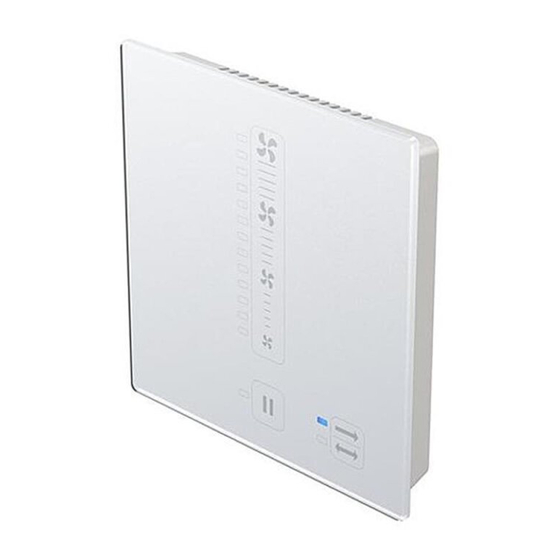
SYSTEM OVERVIEW Construction The sMove controller consists of a base plate for mounting on the inner wall and an operating unit. The operating unit contains the electronics of the sMove and the control panel (acrylic glass cover). With its integrated indicator lights, the control panel also serves as a display interface for the user. -
Page 8: Function
SYSTEM OVERVIEW Function Regler sMove ohne angeschlossene Schnittstelle sMove controller without connected interface If the external interface is not connected, the mode and the intensity of the air flow can be set on the sMove controller. The heat recovery and ventilation modes can easily be set by touching the Mode button. The OFF mode or the pause function can be selected by touching the Off/Pause button. - Page 9 SYSTEM OVERVIEW If the external interface is used to connect a • CO sensor, the CO content in the interior is measured continuously. • hygrostat, the relative humidity in the interior is measured continuously. • VOC sensor, the composition of the air and the resulting air quality are measured continu- ously.
-
Page 10: Design And Features
SYSTEM OVERVIEW Design and features Control panel The control panel is located on the front of the control unit and also serves as a display surface. It is composed of capacitive buttons and various indicator lights. It is operated by touching the various buttons (marked in grey in figure 2). -
Page 11: Electrical Connections
ELECTRICAL CONNECTIONS Electrical connections DANGER Exposed electrical components. Electric shock and injury due to live components (230V, 50Hz)! • Before working on electrical installations, disconnect all affected equipment from the power supply. • Observe the requirements for protection class II when laying the power supply cable. Do not lay or connect live cables. -
Page 12: Controller Smove S4
+ 24 V DC Steckbrücke/ Jumper Lü1 Ub (+) Lü2 Fan-BUS: cable type LiYY3x0.75 / Maximale Kabel-Länge: 33 m (sternförmig) Figure 3: Connection example for controller sMove s4 with cabinet mounted PSU and distribution sMove controller • Installation and operating manual... - Page 13 + 24 V DC Steckbrücke / Jumper Lü1 Ub (+) Lü2 Figure 4: Connection example for controller sMove s4 with flush mounted PSU and distribution Components 1 Plug-in connection 8 Terminal, 2-pole (External interface) 2 Reversible fan 9 Terminal, 5-pole (fan-BUS/...
-
Page 14: Controller Smove S8
ELECTRICAL CONNECTIONS Controller sMove s8 Maximum cable lengths Operating voltage cable, 2-wire, 24 V DC Between power supply unit (PSU) and controller: Max. 100 m Fan-BUS (cable LiYY3x0,75): 1. Star-shaped connection of the fans to the controller: • Between sMove s8 and iV-Smart+/ iV14-Zero/ iV-Light/ iV-Compact: Max. - Page 15 ELECTRICAL CONNECTIONS Connection example for controller sMove s8 with flush-mounted PSU + 24 V DC Lü1 Ub (+) Lü2 V IV III V IV III Fan-BUS: cable type LiYY3x0.75 / V IV III V IV III Maximum length: 33 m each (star-shaped) Figure 6: Connection example for controller sMove s8 with flush mounted PSU and distribution Components...
-
Page 16: Terminal Assignments
ELECTRICAL CONNECTIONS Terminal assignments The terminals on the circuit board are finger-operated spring-loaded terminals. The terminals have a connection capacity of 0.1 to 1.5 mm². They are suitable for solid and stranded wires. The use of wire ferrules is not necessary. If wire ferrules are used, they must increase the cross-section (their material thickness is thereby not included). -
Page 17: Jumper
ELECTRICAL CONNECTIONS Jumper Jumper 2 is used to assign functions to the external interface when a potential-free switching contact is connected (pressure monitor: Opener (normally closed NC) / other sensors: Closer (normally open NO) and for integration into a house control system. The position of the jumper may only be changed in a voltage-free state. -
Page 18: Preparing For Installation
• sMove s4 / s8 incl. control panel PSU: 1 flush-mounted / plasterboard box, min. depth 66 mm • sMove s4 incl. flush-mounted PSU: 1 flush-mounted box / 1 wall-installation box, min. depth 87 mm •... -
Page 19: Dimensioned Drawings
PREPARING FOR INSTALLATION Width Height Depth Designation Ø [mm] [mm] [mm] [mm] Control panel switching PSU NT17-s4 ‒ Control panel switching PSU NT17-s8 ‒ Flush-mounted switching PSU NT17-s8 – – Flush-mounted switching PSU NT17-s4 – 32,5 – Dimensioned drawings sMove controller 1 Guides (4 x) for attaching the operating unit 2 Installation marking TOP... - Page 20 PREPARING FOR INSTALLATION Mounting boxes ≥ 95 (66) Figure 10: Flush-mounted box 60x92 (60x66) 1 Flush-mounted box 60x66 3 Base plate fixing points (2 x) 2 Putzausgleichsring 4 Wall opening (preassembled, box 60x92 only) Ø Figure 11: Plasterboard wall box 61x68 1 Fixing screw for plasterboard wall box 2 Fixing screw for operating unit (2x) Ø...
-
Page 21: Installation And Assembly
INSTALLATION AND ASSEMBLY Installation and assembly DANGER Exposed electrical components. Electric shock and injury due to live components (230V, 50Hz)! • Before working on electrical installations, disconnect all affected equipment from the power supply. • Observe the requirements for protection class II when laying the power supply cable. Do not lay live cables. -
Page 22: Fitting The Wall Openings
► Create a hole for the box in the interior wall. Observe the maximum cable lengths ( 4). Ø sMove s4/s8 with cabinet mounted PSU flush mounted box: Ø 82 mm, depth 66 mm plasterboard box: Ø 68 mm, depth 66 mm sMove s4 with flush-mounted PSU flush mounted box: Ø... -
Page 23: Laying The Cables
INSTALLATION AND ASSEMBLY Laying the cables Requirement: The wall openings are created. sMove s4 / s8 with cabinet mounted PSU ► Lay the operating voltage cable, 2-wire, to the wall opening for the max. 8 x operating unit's connection. 16 V DC ►... -
Page 24: Smove S4 / S8 Controller: Installation With Cabinted Mounted Psu
INSTALLATION AND ASSEMBLY sMove s4 / s8 controller: Installation with cabinted mounted PSU When mounting the sMove controller with a control cabinet power supply, the power supply is mounted and connected on the top-hat rail of the control cabinet. The operating voltage cable and the fan cables are routed to the sMove mounting location (wall opening). - Page 25 INSTALLATION AND ASSEMBLY Installing the wall box NOTE Laying cables whilst live damages the sMove controller! • Lay and connect the cable only while in a voltage-free state. • The installation and connection must only be performed by qualified and trained personnel. Filler for mounting the box, flush-mounted/ plasterboard box min.
-
Page 26: Smove S4 Controller: Installation With Flush-Mounted Switching Psu
INSTALLATION AND ASSEMBLY sMove s4 controller: Installation with flush-mounted switching PSU When mounting the sMove s4 with flush-mounted switching power supply unit, the operating unit is mounted on a flush-mounted or cavity/plasterboard wall box. The flush-mounted swit- ching power supply unit in the box. The fan cables are distributed in the box. Make sure that the socket is deep enough (≤... -
Page 27: Smove S8 Controller: Installation With Flush-Mounted Switching Psu
INSTALLATION AND ASSEMBLY ► Connect the PSU's input cable (blue/brown) via the lustre terminal: • Connect the phase conductor with cable L(brown). • Connect the neutral conductor with cable N (blue). ► Slide the connected PSU into the box. Ensure that the cable end protrudes into the interior space. - Page 28 INSTALLATION AND ASSEMBLY ► Lay the fan-BUS cables in pairs into the flush-mounted box. ► Remove about 8.5 mm of insulation from each fan-BUS cable. ► Fill the space between the interior wall and the box with a suitable filler. ►...
- Page 29 INSTALLATION AND ASSEMBLY Connecting the flush mounted switching PSU DANGER Exposed electrical components. Electric shock and injury due to live components (230V, 50Hz)! • Before working on electrical installations, disconnect all affected equipment from the power supply. • Observe the requirements for protection class II when laying the power supply cable. Do not lay live cables.
-
Page 30: Installing The Operating Unit
The operating unit is mounted onto the installed flush-mounted or cavity wall box for the ope- rating unit. The fan cables for the versions with cabinet power supply unit and for the sMove s4 with flush-mounted power supply unit are located inside the box and distributed in it. - Page 31 INSTALLATION AND ASSEMBLY sMove s4/s8 with cabinet mounted PSU and sMove s4 mit flush-mounted PSU: ► Remove about 8.5 mm of insulation from each fan-BUS cable. ► Connect the fan-BUS cables to terminal blocks, 5-pole, as follows: The cable ends •...
- Page 32 INSTALLATION AND ASSEMBLY NOTE: If jumer 2 is set incorrect on the controller's rear side the controller does not fulfill the desired functions! • Observe the position of Jumper 2. ► Attach Jumper 2 (upper Jumper, in accessories pack) in a way, that the desired function is activated (see electrical connection, page 17).
-
Page 33: Operation
OPERATION Operation The sMove controller consists of a base plate for mounting on the inner wall and an operating unit. The operating unit contains the electronics of the sMove as well as the control panel (acrylic glass cover). The control panel serves as input and display surface for the user. Control panel The control panel is located on the front of the control unit and also serves as a display surface. - Page 34 OPERATION Pause/Off button: A brief press allows you to set the pause function for one, two, four or eight hours as re- quired. In the standard version, pressing the button for 5 seconds allows you to complete- ly switch off all ventilation units connected to the controller. Pressing it again switches the connected ventilation units back on.In Flat version the ventilation unit cannot be shut off completely.
-
Page 35: First Activation
OPERATION First activation When the sMove controller is put into operation for the first time, the reversing fans of the ven- tilation units automatically start at the lowest output level (25 %) in the heat recovery operating mode. Requirements: The controller is connected to the power supply. ►... -
Page 36: Setting Heat Recovery And Continuous Ventilation Modes
OPERATION Setting heat recovery and continuous ventilation modes Setting heat recovery mode The ventilation unit operates on the generator principle. The fan changes direction at 70-second intervals. The integrated thermal accumulator charges itself with heat energy from the room's air as it flows to the exterior (extract air). When the reversible fan changes direction, it releases the stored heat energy into the incoming outside air (supply air). -
Page 37: Pause Function
OPERATION Pause function Setting pause function mode When setting the pause function, the controller will first switch off the connected ventilation units. Pause duration can be selected for one, two, four or eight hours. After the pause, all ventilation units connected to the controller will restart in the last stored configuration of output level and mode. - Page 38 OPERATION Display of remaining pause time If the controller sMove is in pause, the remaining time in which the controller is in pause can be viewed. Requirements: The controller is in pause function. Remaining ► Press any button on the control panel. pause time The control panel is activated.
-
Page 39: Set Output Level
OPERATION Set output level The intensity of the ventilation can be adjusted continuously by moving the slide control, or in four steps by touching the fan icons on the slide control. The fan icons on the slide control indicate output levels 1 and 4 . -
Page 40: Confirm Filter Change
OPERATION Set the Boost function The controller can be manually set to Boost to quickly remove moisture or odour peaks. In the Boost function, the output of the reversing fan increases to 100 % for 15 minutes. The operating mode is maintained. The output is then lowered back to the original level. -
Page 41: View Hours Run
OPERATION View hours run The sMove controller comes with an integrated hours-run counter. The operating time is displayed in days. The maximum displayable number is 4,000 days. One day corresponds to a calculation period of 24 hours. There is no further split within these 24 hours. The operating time is displayed as a 4-digit number. -
Page 42: Cleaning And Maintenance
• lint-free, soft cloth • soft brush Recommended maintenance The maintenance tasks and intervals listed here are recommended by inVENTer GmbH to maintain the functionality and performance of the sMove controller. Depending on requirements and/or air quality, your personal maintenance plan may deviate from these recommendations. -
Page 43: Specifications
SPECIFICATIONS Specifications Feature Value Protection class (EN 61140) / IP20 / II Type of protecion (EN 60529) Input voltage Switching PSU / mains [V AC] [Hz] 230 / 50 Output voltage Switching PSU / operating voltage [V DC] Power consumption (Standby) [W] <... -
Page 44: Accessories And Spare Parts
ACCESSORIES AND SPARE PARTS Accessories and spare parts To order parts for your sMove controller, contact your nearest factory outlet or our service staff. Accessories Component Item number sensor CS1 1004-0145 Hygrostat HYG18 1002-0044 Hygrostat HYG12 1002-0015 Flush-mounted box 60x66 3002-0244 Flush-mounted box 60x90 1003-0104... -
Page 45: Troubleshooting And Disposal
Troubleshooting If your ventilation units or controllers are not functioning properly, consult the following troubleshooting table. If the fault persists, contact your supplier, distributor or the technical service department at inVENTer GmbH (see chapter 11 – service) Malfunction Possible cause... -
Page 46: Guarantee And Warranty
Failure to observe the intended use will invalidate all warranty claims. Manufacturer guarantee inVENTer GmbH provides a five-year guarantee for all electrical components and the wall mounting sleeve, as well as a thirty-year guarantee on the heat accumulator ceramic. This covers premature product wear. - Page 47 WEBSITE: WWW.INVENTER.DE CEO: ANNETT WETTIG VAT ID NUMBER: DE 815494982 JENA DISTRICT COURT HRB 510380 PICTURE CREDITS: © INVENTER GMBH 2014-19 ALL RIGHTS RESERVED: © INVENTER GMBH 2014-19 SUBJECT TO MODIFICATIONS. ALL INFORMATION IS SUPPLIED WITHOUT GUARANTEE. NO LIABILITY IS ACCEPTED FOR PRINTING ERRORS.
- Page 48 GmbH Ortsstraße 4a D-07751 Löberschütz +49 (0) 36427 211-0 +49 (0) 36427 211-113 info@inventer.de Version 04/2019 Subject to changes Article number 5021-0016 www.inventer.eu © inVENTer GmbH 2014–19...
Need help?
Do you have a question about the sMove s4 and is the answer not in the manual?
Questions and answers