Table of Contents
Advertisement
Quick Links
Model No. PFEVEX74010.0
Serial No.
Write the serial number in the
space above for reference.
Serial Number Decal
(under frame)
QUESTIONS?
If you have questions, or if there are
missing parts, please contact us:
UK
Call: 08457 089 009
From Ireland: 053 92 36102
Website: www.iconsupport.eu
E-mail: csuk@iconeurope.com
Write:
ICON Health & Fitness, Ltd.
c/o HI Group PLC
Express Way
Whitwood, West Yorkshire
WF10 5QJ
UK
AUSTRALIA
Call: 1-800-237-173
E-mail:
australiacc@iconfitness.com
CAUTION
Read all precautions and instruc-
tions in this manual before using
this equipment. Keep this manual
for future reference.
Get other manuals https://www.bkmanuals.com
USER'S MANUAL
www.iconeurope.com
Advertisement
Table of Contents

Subscribe to Our Youtube Channel
Related Manuals for Pro-Form 300 ZLX


Summary of Contents for Pro-Form 300 ZLX
- Page 1 Model No. PFEVEX74010.0 USER'S MANUAL Serial No. Write the serial number in the space above for reference. Serial Number Decal (under frame) QUESTIONS? If you have questions, or if there are missing parts, please contact us: Call: 08457 089 009 From Ireland: 053 92 36102 Website: www.iconsupport.eu E-mail: csuk@iconeurope.com...
-
Page 2: Table Of Contents
TABLE OF CONTENTS WARNING DECAL PLACEMENT ............. .2 IMPORTANT PRECAUTIONS . -
Page 3: Important Precautions
IMPORTANT PRECAUTIONS WARNING: To reduce the risk of serious injury, read all important precautions and instructions in this manual and all warnings on your exercise bike before using your exercise bike. ICON assumes no responsibility for personal injury or property damage sustained by or through the use of this product. -
Page 4: Before You Begin
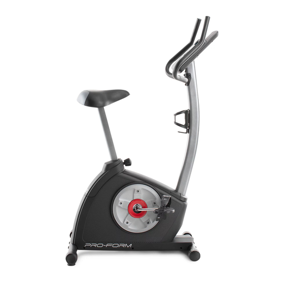
The 300 ZLX exercise bike pro- us. The model number and the location of the serial vides an impressive selection of features designed to... -
Page 5: Assembly
ASSEMBLY Assembly requires two persons. Place all parts of the exercise bike in a cleared area and remove the packing materials. Do not dispose of the packing materials until assembly is completed. In addition to the included tool(s), assembly requires a Phillips screwdriver , an adjustable wrench , and a rubber mallet... - Page 6 To make assembly easier, read the information on page 5 before you begin. Attach the Rear Stabilizer (3) to the Frame (1) with two M10 x 95mm Patch Screws (76). 2. Attach the Front Stabilizer (2) to the Frame (1) with two M10 x 95mm Patch Screws (76).
- Page 7 3. Loosen the Adjustment Knob (27) in the Frame (1) a few turns. Orient the Seat Post (6) as shown. Then, pull the Adjustment Knob (27) outward and insert Adjustment the Seat Post into the Frame (1). Slide the Seat Holes Post upward or downward to the desired posi- tion, and release the Adjustment Knob.
- Page 8 5. Apply some of the included grease to an M6 x 70mm Bolt Set (50). Orient the Handlebar (5) and the Upright (4) as shown. While a second person holds the Handlebar (5) near the Upright (4), insert the Extension Wire (59) upward through the Handlebar.
- Page 9 7. While another person holds the Console (13) near the Handlebar (5), connect the wires on the Console to the Extension Wire (59) and the Pulse Wire (61). Insert the excess wire downward into the Handlebar (5) or upward into the Console (13). Tip: Avoid pinching the wires.
- Page 10 9. Slide the Front Shield Cover (7) upward onto the Upright (4). While another person holds the Upright (4) near the Frame (1), connect the Extension Wire (59) to the Wire Harness (58). Avoid pinching Insert the Upright (4) into the Frame (1). the wires Tip: Avoid pinching the wires.
-
Page 11: How To Use The Exercise Bike
HOW TO USE THE EXERCISE BIKE HOW TO ADJUST THE HEIGHT OF THE SEAT HOW TO ADJUST THE HORIZONTAL POSITION OF THE SEAT For effective exercise, the seat should be at the proper height. As you pedal, there should be a slight To adjust the hori- bend in your knees when the pedals are in the lowest zontal position of... - Page 12 HOW TO ADJUST THE ANGLE OF THE HOW TO LEVEL THE EXERCISE BIKE HANDLEBAR If the exercise To adjust the bike rocks slightly angle of the han- on your floor dur- dlebar, first ing use, turn one loosen the adjust- or both of the lev- Handlebar ment knob a few...
- Page 13 CONSOLE DIAGRAM Workouts Button Volume Buttons Display Button Resistance Buttons FEATURES OF THE CONSOLE For example, lose unwanted pounds with the 8-week Weight Loss workout. iFit workouts control the resis- This console offers an array of features designed to tance of the pedals while the voice of a personal make your workouts more effective and enjoyable.
- Page 14 HOW TO USE THE MANUAL MODE 4. Follow your progress with the display. 1. Begin pedaling or press any button on the The console offers several display modes. The console to turn on the console. display mode that you select will determine which workout information is shown.
- Page 15 Pulse—This display will show your heart rate When your pulse is detected, dashes will appear when you use the handgrip pulse sensor (see step in the display, and then your heart rate will be 5 below). shown. For the most accurate heart rate reading, hold the contacts for at least 15 seconds.
- Page 16 HOW TO USE A PRESET WORKOUT If a different resistance level and/or target speed is programmed for the next segment, the resistance 1. Begin pedaling or press any button on the level and/or the target speed will flash in the dis- console to turn on the console.
- Page 17 HOW TO USE AN IFIT WORKOUT A moment after you select a workout, the voice of a personal trainer will begin guiding you through iFit cards are available separately. To purchase iFit your workout. cards, go to www.iFit.com or see the front cover of this manual.
- Page 18 HOW TO CHANGE THE CONSOLE SETTINGS 3. Select a unit of measurement if desired. The console features a display settings mode that The console can show pedaling speed and dis- allows you to select a backlight option and to select a tance in either miles or kilometers.
-
Page 19: Maintenance And Troubleshooting
MAINTENANCE AND TROUBLESHOOTING Inspect and tighten all parts of the exercise bike regu- Next, rotate the Left larly. Replace any worn parts immediately. Crank Arm (20) to a vertical position with To clean the exercise bike, use a damp cloth and a the end of the Left small amount of mild soap. - Page 20 HOW TO ADJUST THE DRIVE BELT Next, rotate the Right Crank Arm (19) to a vertical position with the end of the Right Crank Arm pointing If you can feel the pedals slip while you are pedaling, upward. even when the resistance is adjusted to the highest level, the drive belt may need to be adjusted.
-
Page 21: Exercise Guidelines
EXERCISE GUIDELINES WARNING: Burning Fat—To burn fat effectively, you must exer- cise at a low intensity level for a sustained period of Before beginning this time. During the first few minutes of exercise, your or any exercise program, consult your physi- body uses carbohydrate calories for energy. -
Page 22: Part List
PART LIST—Model No. PFEVEX74010.0 R0910A Key No. Qty. Description Key No. Qty. Description Frame Resistance Arm Front Stabilizer M6 x 70mm Bolt Set Rear Stabilizer M6 x 60mm Bolt Set Upright Arm Lock Handlebar C-magnet Seat Post Drive Belt Front Shield Cover Magnet Top Shield Cover Clamp... -
Page 23: Exploded Drawing
EXPLODED DRAWING—Model No. PFEVEX74010.0 R0910A Get other manuals https://www.bkmanuals.com... -
Page 24: Ordering Replacement Parts
ORDERING REPLACEMENT PARTS To order replacement parts, please see the front cover of this manual. To help us assist you, be prepared to provide the following information when contacting us: • the model number and serial number of the product (see the front cover of this manual) •...
Need help?
Do you have a question about the 300 ZLX and is the answer not in the manual?
Questions and answers
Hi there, our Proforma 300ZLX has set to the 'heaviest pedal push' so very hard to peddle. It changes on the screen to Resistance 1 etc but it doesn't change on the belt. Can you advise what we could do to try and fix this please?
To fix the resistance issue on your Pro-Form 300 ZLX exercise bike when it is stuck on the heaviest pedal push, you may need to adjust the drive belt. Follow these steps:
1. Remove the right pedal by turning it counterclockwise with an adjustable wrench.
2. Remove the seat post, top shield cover, rear shield cover, front shield cover, right disc cover, right pedal disc, and right shield.
3. Locate the drive belt and check if it is too tight or misaligned.
4. Loosen the M6 x 20mm Hex Screw to adjust the belt tension as needed.
5. Reassemble all removed parts in reverse order.
This should help restore proper resistance adjustment.
This answer is automatically generated