Table of Contents
Advertisement
proform.com
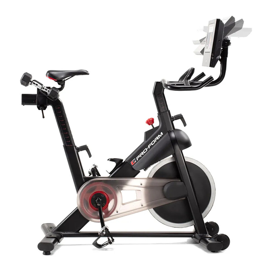
Model No. PFEX16718.0
Serial No.
Write the serial number in the space
above for reference.
Serial
Number
Decal
ACTIVATE YOUR
WARRANTY
To register your product and
activate your warranty today,
go to my.proform.com.
CUSTOMER CARE
For service at any time, go to
proformservice.com.
Or call 1-888-533-1333
Mon.–Fri. 6 a.m.–6 p.m. MT
Sat. 8 a.m.–12 p.m. MT
Please do not contact the store.
CAUTION
Read all precautions and
instructions in this manual before
using this equipment. Keep this
manual for future reference.
USER'S MANUAL
Advertisement
Table of Contents

Subscribe to Our Youtube Channel
Related Manuals for Pro-Form Smart Power 10.0


Summary of Contents for Pro-Form Smart Power 10.0
- Page 1 proform.com USER’S MANUAL Model No. PFEX16718.0 Serial No. Write the serial number in the space above for reference. Serial Number Decal ACTIVATE YOUR WARRANTY To register your product and activate your warranty today, go to my.proform.com. CUSTOMER CARE For service at any time, go to proformservice.com.
-
Page 2: Table Of Contents
TABLE OF CONTENTS WARNING DECAL PLACEMENT ............. . .2 IMPORTANT PRECAUTIONS . -
Page 3: Important Precautions
IMPORTANT PRECAUTIONS WARNING: To reduce the risk of serious injury, read all important precautions and instructions in this manual and all warnings on your exercise bike before using your exercise bike. ICON assumes no responsibility for personal injury or property damage sustained by or through the use of this product. - Page 4 STANDARD SERVICE PLANS...
-
Page 5: Before You Begin
Thank you for choosing the new PROFORM reading this manual, please see the front cover of this ® SMART POWER 10.0 exercise bike. Cycling is an manual. To help us assist you, note the product model effective exercise for increasing cardiovascular fit- number and serial number before contacting us. -
Page 6: Part Identification Chart
PART IDENTIFICATION CHART Use the drawings below to identify the small parts needed for assembly. The number in parentheses below each drawing is the key number of the part, from the PART LIST near the end of this manual. The number following the key number is the quantity needed for assembly. -
Page 7: Assembly
ASSEMBLY • To hire an authorized service technician to requires the following tool(s): assemble this product, call 1-800-445-2480. one Phillips screwdriver • Assembly requires two persons. one adjustable wrench • Place all parts in a cleared area and remove the one rubber mallet packing materials. - Page 8 2. If there are shipping tubes (not shown) attached to the front and rear of the Frame (1), remove and discard the shipping tubes and the hardware attaching them. Orient the Front Stabilizer (2) as shown, and attach it to the Frame (1) with two M10 x 25mm Screws (69).
- Page 9 4. Tip: See the inset drawing to learn how to operate the Adjustment Handle (14). Loosen handle Locate the Adjustment Handle (14) on the rear of the Frame (1). Pull the Adjustment Handle Pull handle outward, and insert the Saddle Post (7) into the Frame.
- Page 10 6. Note: You can attach your own pedals if desired. Identify the Right Pedal (16). Using the included wrench, firmly tighten the Right Pedal clockwise into the Right Crank Arm (18). Firmly tighten the Left Pedal (17) counterclockwise into the Left Crank Arm (not shown).
- Page 11 8. See the inset drawing. Connect the connector on the Upper Wire (B) to the connector on the Lower Wire (82). Next, tighten the zip tie (D) around the indicated mark (E) on the Upper Wire (B). Then, cut off the excess zip tie.
- Page 12 10. While a second person holds the Console Mount (5) near the Handlebar (4), connect the 6-pin and 8-pin Wires (90, 91) in the Console Mount to the matching connectors on the Upper Wire (B) in the Handlebar. Avoid pinching the wires Tip: Avoid pinching the wires.
- Page 13 12. Have a second person hold the Console (6) near the Console Bracket (26). Plug the 6-pin and 8-pin Wires (90, 91) into the matching receptacles on the back of the Console (6); make sure to plug the Wire marked with red into the receptacle marked with red, and plug the Wire marked with yellow into the receptacle marked with yellow.
- Page 14 14. Plug the Power Adapter (86) into the receptacle in the Frame (1). Note: To plug the Power Adapter (86) into an outlet see HOW TO PLUG IN THE POWER ADAPTER on page 15. 15. After the exercise bike is assembled, inspect it to make sure that it is assembled correctly, that it functions properly, and that all parts are properly tightened.
-
Page 15: How To Use The Exercise Bike
HOW TO USE THE EXERCISE BIKE HOW TO PLUG IN THE POWER ADAPTER HOW TO ADJUST THE ANGLE OF THE SADDLE IMPORTANT: If the exercise bike has been exposed You can adjust the angle of the saddle to the position to cold temperatures, allow it to warm to room tem- that is most comfortable. - Page 16 HOW TO ADJUST THE SADDLE POST HOW TO ADJUST THE HANDLEBAR For effective exercise, the saddle should be at the To adjust the height of the proper height. As you pedal, there should be a slight handlebar, first bend in your knees when the pedals are in the lowest position.
- Page 17 HOW TO USE THE PEDALS HOW TO USE THE BRAKE KNOB To use the pedals To change the resis- (G), insert your shoes tance of the pedals, into the toe cages press the buttons on and pull the ends of the console (see step the toe straps.
- Page 18 CONSOLE DIAGRAM FEATURES OF THE CONSOLE When you use the manual mode of the console, you can change the resistance of the pedals with the touch The advanced console offers an array of features of a button. designed to make your workouts more effective and enjoyable.
- Page 19 HOW TO ACTIVATE THE CONSOLE HOW TO USE THE TOUCH SCREEN The included power adapter must be used to operate The console features a tablet with a full-color touch the exercise bike. See HOW TO PLUG IN THE screen. The following information will help you use the POWER ADAPTER on page 15.
- Page 20 HOW TO SET UP THE CONSOLE 5. Check for firmware updates. Before you use the exercise bike for the first time, set First, touch the profile button, touch Settings, touch Maintenance, and then touch Update. The up the console. console will check for firmware updates. For more 1.
- Page 21 HOW TO USE THE MANUAL MODE To select the desired display mode or to view statistics and charts, drag downward on the screen. 1. Touch the screen or press any button on the You can also touch the more button (+ symbol) to console to turn on the console.
- Page 22 HOW TO USE A MAP WORKOUT OR AN ONBOARD To draw your own map for a workout, see HOW TO WORKOUT CREATE A DRAW-YOUR-OWN-MAP WORKOUT on page 24. 1. Touch the screen or press any button on the console to turn on the console. When you select a workout, the screen will show an overview of the workout that includes details See HOW TO ACTIVATE THE CONSOLE on...
- Page 23 If the resistance level is too high or too low, you When the workout comes to an end, a workout can manually override the setting by pressing the summary will appear on the screen. If desired, you Digital Quick Resistance buttons. If you press a can publish your results using one of the options on Digital Quick Resistance button, you can then the screen.
- Page 24 HOW TO CREATE A DRAW-YOUR-OWN-MAP If you make a mistake, touch Undo on the left side WORKOUT of the screen. 1. Touch the screen or press any button on the The screen will display the elevation and distance console to turn on the console. statistics for your workout.
- Page 25 HOW TO USE AN IFIT WORKOUT 4. Select an iFit workout that you have previously added to your schedule on iFit.com. To use an iFit workout, the console must be connected IMPORTANT: Before iFit workouts will load, you to a wireless network (see HOW TO CONNECT TO A must add them to your schedule on iFit.com WIRELESS NETWORK on page 27).
- Page 26 HOW TO CHANGE CONSOLE SETTINGS 3. View the console tour presentation. IMPORTANT: Some of the settings and features To view a tour presentation that will guide you described may not be enabled. Occasionally, a through the features of the console, touch How It firmware update may cause your console to function Works.
- Page 27 HOW TO CONNECT TO A WIRELESS NETWORK Note: You must have your own wireless network and an 802.11b/g/n router with SSID broadcast To use iFit workouts and to use several other features enabled (hidden networks are not supported). of the console, the console must be connected to a wireless network.
- Page 28 HOW TO USE THE SOUND SYSTEM THE OPTIONAL CHEST HEART RATE MONITOR To play music or audio books through the console Whether your sound system while you exercise, plug a 3.5 mm male goal is to to 3.5 mm male audio cable (not included) into the burn fat or to jack on the right side of the console and into a jack on strengthen your...
-
Page 29: Fcc Information
FCC INFORMATION This equipment has been tested and found to comply with the limits for a Class B digital device, pursuant to part 15 of the FCC Rules. These limits are designed to provide reasonable protection against harmful interference in a residential installation. This equipment generates, uses, and can radiate radio frequency energy and, if not installed and used in accordance with the instructions, may cause harmful interference to radio communications. -
Page 30: Maintenance And Troubleshooting
MAINTENANCE AND TROUBLESHOOTING HOW TO MAINTAIN THE EXERCISE BIKE HOW TO ADJUST THE REED SWITCH Regular maintenance is important for optimal If the console does not display correct feedback, the performance and to reduce wear. Inspect and properly reed switch should be adjusted. tighten all parts each time the exercise bike is used. - Page 31 HOW TO ADJUST THE DRIVE BELT Then, tighten the M10 x 60mm Screw (65) until the Drive Belt (not shown) is tight. If you feel the pedals slip while you are pedaling, even when the resistance is adjusted to the highest level, When the Drive Belt (not shown) is tight, reattach the the drive belt may need to be adjusted.
-
Page 32: Exercise Guidelines
EXERCISE GUIDELINES Aerobic Exercise—If your goal is to strengthen your WARNING: cardiovascular system, you must perform aerobic Before beginning this exercise, which is activity that requires large amounts or any exercise program, consult your physi- of oxygen for prolonged periods of time. For aerobic cian. -
Page 33: Part List
PART LIST Model No. PFEX16718.0 R1218A Key No. Qty. Description Key No. Qty. Description Frame Foot Front Stabilizer Leveling Foot Rear Stabilizer Handlebar/Upper Wire Saddle Post Cap Console Mount Bracket Mount Console Reed Switch/Wire Saddle Post Clamp Saddle Hand Weight Saddle Arm Flywheel Washer Saddle Carriage... -
Page 34: Exploded Drawing
EXPLODED DRAWING A Model No. PFEX16718.0 R1218A... - Page 35 EXPLODED DRAWING B Model No. PFEX16718.0 R1218A...
-
Page 36: Ordering Replacement Parts
ORDERING REPLACEMENT PARTS To order replacement parts, please see the front cover of this manual. To help us assist you, be prepared to provide the following information when contacting us: • the model number and serial number of the product (see the front cover of this manual) •...
Need help?
Do you have a question about the Smart Power 10.0 and is the answer not in the manual?
Questions and answers
Where is the power plug on bike
How to the console work