Advertisement
Table of Contents
- 1 Table of Contents
- 2 Warning Decal Placement
- 3 Important Precautions
- 4 Before You Begin
- 5 Part Identification Chart
- 6 Assembly
- 7 How to Use the Exercise Bike
- 8 Fcc Information
- 9 Maintenance and Troubleshooting
- 10 Exercise Guidelines
- 11 Part List
- 12 Exploded Drawing
- 13 Ordering Replacement Parts
- 14 Limited Warranty
- Download this manual
www.proform.com
Model No. PFEX14914.0
Serial No.
Write the serial number in the
space above for reference.
Serial Number
Decal
ACTIVATE YOUR
WARRANTY
To register your product and
activate your warranty today,
go to www.proformservice.com/
registration.
CUSTOMER CARE
For service at any time, go to
www.proformservice.com.
Or call 1-888-533-1333
Mon.–Fri. 6 a.m.–6 p.m. MT
Sat. 8 a.m.–12 p.m. MT
Please do not contact the store.
CAUTION
Read all precautions and instruc-
tions in this manual before using
this equipment. Keep this manual
for future reference.
USER'S MANUAL
Advertisement
Table of Contents

Subscribe to Our Youtube Channel
Related Manuals for Pro-Form PFEX14914.0


Summary of Contents for Pro-Form PFEX14914.0
- Page 1 USER’S MANUAL Model No. PFEX14914.0 Serial No. Write the serial number in the space above for reference. Serial Number Decal ACTIVATE YOUR WARRANTY To register your product and activate your warranty today, go to www.proformservice.com/ registration. CUSTOMER CARE For service at any time, go to www.proformservice.com.
-
Page 2: Table Of Contents
TABLE OF CONTENTS WARNING DECAL PLACEMENT ............. . .2 IMPORTANT PRECAUTIONS . -
Page 3: Important Precautions
IMPORTANT PRECAUTIONS WARNING: To reduce the risk of serious injury, read all important precautions and instructions in this manual and all warnings on your exercise bike before using your exercise bike. ICON assumes no responsibility for personal injury or property damage sustained by or through the use of this product. - Page 5 STANDARD SERVICE PLANS...
-
Page 6: Before You Begin
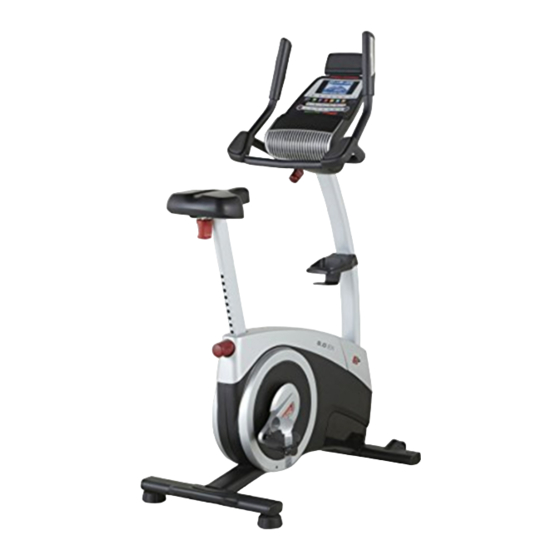
BEFORE YOU BEGIN Thank you for selecting the revolutionary PROFORM reading this manual, please see the front cover of this ® 8.0 EX exercise bike. Cycling is one of the most effec- manual. To help us assist you, note the product model tive exercises for increasing cardiovascular fitness, number and serial number before contacting us. -
Page 7: Part Identification Chart
PART IDENTIFICATION CHART Use the drawings below to identify the small parts needed for assembly. The number in parentheses below each drawing is the key number of the part, from the PART LIST near the end of this manual. The number following the key number is the quantity needed for assembly. -
Page 8: Assembly
ASSEMBLY • To hire an authorized service technician to • To identify small parts, see page 7. assemble this product, call 1-800-445-2480. • In addition to the included tool(s), assembly • Assembly requires two persons. requires the following tools: one Phillips screwdriver •... - Page 9 3. Set a sturdy piece of packing material under the front of the Frame (1). Attach the Front Stabilizer (2) to the Frame (1) with two M10 x 98mm Screws (53). Remove the packing material. 4. With the help of a second person, raise the Upright (4) to the vertical position.
- Page 10 5. Attach the Accessory Tray (8) to the Upright (4) with an M6 x 50mm Screw (89). 6. Have a second person hold the Handlebar (5) near the Upright (4). See the inset drawing. Route the Upper Wire (87) through the Pivot Post (78) and the Pivot Bracket (71) as shown.
- Page 11 7. While a second person holds the Console (13) near the Pivot Bracket (71), connect the wires on the Console to the Upper Wire (87) and the Pulse Wires (61). Insert the excess wire downward through the Pivot Bracket (71). Do not insert the excess wire into the Console (13);...
- Page 12 9. Remove the Seat Knob (26) from the Seat Bracket (30) inside the Seat Carriage (24). Next, hold the Seat Carriage (24) on the Seat Post (6). Insert the Seat Knob (26) upward into the Seat Post, and tighten the Seat Knob into the Seat Bracket (30) inside the Seat Carriage.
- Page 13 11. Identify the Right Pedal (21). Using an adjustable wrench, firmly tighten the Right Pedal (21) clockwise into the Right Crank Arm (19). Firmly tighten the Left Pedal (not shown) coun- terclockwise into the Left Crank Arm (not shown). IMPORTANT: You must turn the Left Pedal coun- terclockwise to attach it.
- Page 14 13. Plug the Power Adapter (67) into the receptacle on the frame of the exercise bike. Note: To plug the Power Adapter (67) into an outlet, see HOW TO PLUG IN THE POWER ADAPTER on page 15. 14. After the exercise bike is assembled, inspect it to make sure that it is assembled correctly and that it functions properly.
-
Page 15: How To Use The Exercise Bike
HOW TO USE THE EXERCISE BIKE HOW TO PLUG IN THE POWER ADAPTER HOW TO ADJUST THE LATERAL POSITION OF THE SEAT IMPORTANT: If the exercise bike has been exposed to cold temperatures, allow it to warm to room To adjust the lateral temperature before you plug in the power adapter. - Page 16 HOW TO ADJUST THE CONSOLE HOW TO LEVEL THE EXERCISE BIKE The console can be If the exercise bike adjusted to several rocks slightly on angles. To adjust your floor during the console, turn the use, turn one or console knob until both of the leveling the console is at the feet beneath the...
- Page 17 CONSOLE DIAGRAM MAKE YOUR FITNESS GOALS A REALITY WITH Upload your workout results to the iFit cloud IFIT.COM and track your accomplishments. With your new iFit-compatible fitness equipment, you can use an array of features on iFit.com to make your Set calorie, time, or distance goals for your fitness goals a reality: workouts.
- Page 18 FEATURES OF THE CONSOLE HOW TO USE THE MANUAL MODE The advanced console offers an array of features 1. Begin pedaling or press any button on the designed to make your workouts more effective and console to turn on the console. enjoyable.
- Page 19 Distance (Dist.)—This display mode will show When a wireless iFit module the distance that you have pedaled in miles or is connected, the wireless kilometers. symbol at the top of the dis- play will show the strength of Pulse—This display mode will show your heart rate your wireless signal.
- Page 20 6. Turn on the fan if desired. The maximum resistance level and the maximum speed for the workout will also appear in the The fan has low and high display. speed settings. Press the fan 3. Start the workout. increase and decrease but- tons repeatedly to select a fan speed or to turn off the fan.
- Page 21 If the resistance level for the current segment is Then, press the increase and decrease buttons too high or too low, you can manually override the next to the Enter button to set the desired goal. setting by pressing the Quick Resistance buttons. IMPORTANT: When the current segment of the 3.
- Page 22 HOW TO USE AN IFIT WORKOUT Press the Map button, the Train button, or the Lose Wt. button to download the next workout of that You must have an iFit module to use an iFit workout. type in your schedule. To purchase an iFit module at any time, go to www.iFit.com or call the telephone number on the Press the Compete button to compete in a race...
- Page 23 6. Follow your progress with the display. HOW TO USE THE CHARGING PORT See step 4 on page 18. The console features a charging port that you can use to charge USB-compatible devices, such as The My Trail tab will show a map of the trail or it will smartphones, while you exercise.
- Page 24 HOW TO CHANGE CONSOLE SETTINGS To view distance in miles, select ENGLISH. To view distance in kilometers, select METRIC. 1. Select the settings mode. Demo—The console features a display demo To select the settings mode, press the gear button. mode, designed to be used if the exercise bike is The settings information will appear in the display.
-
Page 25: Fcc Information
FCC INFORMATION This equipment has been tested and found to comply with the limits for a Class B digital device, pursuant to part 15 of the FCC Rules. These limits are designed to provide reasonable protection against harmful interference in a residential installation. This equipment generates, uses, and can radiate radio frequency energy and, if not installed and used in accordance with the instructions, may cause harmful interference to radio communications. -
Page 26: Maintenance And Troubleshooting
MAINTENANCE AND TROUBLESHOOTING MAINTENANCE HOW TO ADJUST THE DRIVE BELT Inspect and tighten all parts of the exercise bike If the pedals slip while you are pedaling, even while the regularly. Replace any worn parts immediately. resistance is adjusted to the highest setting, the drive belt may need to be adjusted. - Page 27 HOW TO ADJUST THE REED SWITCH Locate the Reed Switch (57). Rotate the Left Crank Arm (20) until a Magnet (55) is aligned with the Reed If the console does not display correct feedback, the Switch. Next, loosen the M5 x 16mm Flat Head Screw reed switch should be adjusted.
-
Page 28: Exercise Guidelines
EXERCISE GUIDELINES Burning Fat—To burn fat effectively, you must exer- WARNING: cise at a low intensity level for a sustained period of Before beginning this time. During the first few minutes of exercise, your or any exercise program, consult your physi- body uses carbohydrate calories for energy. -
Page 29: Part List
PART LIST Model No. PFEX14914.0 R1114A Key No. Qty. Description Key No. Qty. Description Frame Knob Nut Front Stabilizer M8 x 76mm Bolt Rear Stabilizer J-bolt Upright #10 x 12mm Screw Handlebar M10 x 98mm Screw Seat Post Drive Belt... -
Page 30: Exploded Drawing
EXPLODED DRAWING A Model No. PFEX14914.0 R1114A... - Page 31 EXPLODED DRAWING B Model No. PFEX14914.0 R1114A...
-
Page 32: Ordering Replacement Parts
ORDERING REPLACEMENT PARTS To order replacement parts, please see the front cover of this manual. To help us assist you, be prepared to provide the following information when contacting us: • the model number and serial number of the product (see the front cover of this manual) •...
Need help?
Do you have a question about the PFEX14914.0 and is the answer not in the manual?
Questions and answers
The fan in the console is not working. What is the part number for the replacement fan?