Table of Contents
Advertisement
Quick Links
Advertisement
Table of Contents

Subscribe to Our Youtube Channel
Related Manuals for TYAN FS65-B5521


Summary of Contents for TYAN FS65-B5521
- Page 1 FS65-B5521 MicroServer Series Service Engineer’s Manual http://www.tyan.com...
- Page 2 http://www.tyan.com...
- Page 3 Neither this manual, nor any material contained herein, may be reproduced without written consent of manufacturer. ® Copyright 2013 MiTAC International Corporation. All rights reserved. TYAN a registered trademark of MiTAC International Corporation. Version 1.0 Disclaimer Information contained in this document is furnished by MiTAC International Corporation and has been reviewed for accuracy and reliability prior to printing.
- Page 4 There will be danger of explosion if battery is incorrectly replaced. Replace only with the same or equivalent type recommended by manufacturer. Dispose of used battery according to manufacturer instructions and in accordance with your local regulations. http://www.tyan.com...
- Page 5 About this Manual This manual is intended for experienced users and integrators with hardware knowledge of personal computers. It is aimed to provide you with instructions on installing your TYAN FS65-B5521. How this guide is organized This guide contains the following parts:...
- Page 6 Safety and Compliance Information Before installing and using TYAN FS65-B5521, take note of the following precautions: ·Read all instructions carefully. ·Do not place the unit on an unstable surface, cart, or stand. ·Do not block the slots and opening on the unit, which are provided for ventilation.
- Page 7 You must become familiar with the safety information in this guide before you install, operate, or service TYAN products. Symbols on Equipment Caution. This symbol indicates a potential hazard.
- Page 8 · Make sure racks are coupled together if it is a multiple-rack installation. · Make sure the rack is level and stable before installing an appliance in the rack. · Make sure the leveling jacks are extended to the floor. http://www.tyan.com...
- Page 9 If you do not ground the Green/Yellow tab, it can cause an electrical shock due to high leakage currents. · Do not place objects on AC power cords or cables. Arrange them so that no http://www.tyan.com...
- Page 10 TYAN, your authorized TYAN partner, or their agents. Equipment Modifications · Do not make mechanical modifications to the system. TYAN is not responsible for the regulatory compliance of TYAN equipment that has been modified.
- Page 11 – Liquid has been spilled on the product or an object has fallen into the product. – The product has been exposed to rain or water. – The product has been dropped or damaged. – The product does not operate normally when you follow the operating instructions. http://www.tyan.com...
- Page 12 http://www.tyan.com...
-
Page 13: Table Of Contents
Table of Contents Chapter 1: Overview............... 17 About the TYAN FS65-B5521 ..........17 Product Models............... 17 Features.................. 18 Standard Parts List ..............22 1.4.1 Box Contents..............22 1.4.2 Accessories ..............22 About the Product..............23 1.5.1 System Front View............23 1.5.2... - Page 14 5.3.10 Power Management Configuration........ 103 5.3.11 Serial Port Console Redirection ........104 5.3.12 CPU PPM Configuration..........105 Chipset Menu ............... 107 5.4.1 South Bridge..............108 5.4.2 North Bridge ..............109 5.4.3 WatchDog Timer Configuration ........112 Boot ..................113 Security................. 115 http://www.tyan.com...
- Page 15 Save & Exit ................120 Chapter 6: Diagnostics ..............123 Flash Utility ................123 AMIBIOS Post Code (Aptio) ..........124 Appendix I: Cable Connection Tables ........131 Appendix II: FRU Parts Table ............133 Appendix III: Technical Support ..........135 http://www.tyan.com...
- Page 16 NOTE http://www.tyan.com...
-
Page 17: Chapter 1: Overview
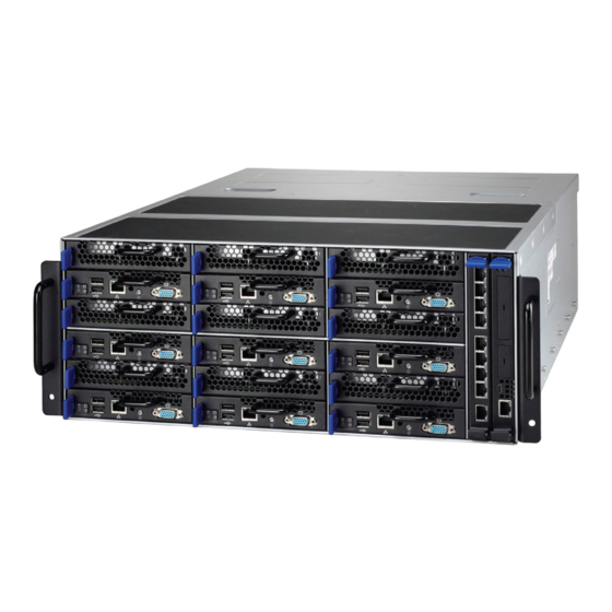
® TYAN also offers the FS65-B5521 in a version that can support up to 54 2.5” fixed hard drives. The FS65-B5521 uses TYAN’s latest chassis featuring a robust structure and a solid mechanical enclosure. All of this provides FS65-B5521 the power and flexibility to meet the needs of nowadays server application. -
Page 18: Features
Features TYAN FS65B5521 (B5521F65X9-090PV6R) Form Factor 4U Rackmount Frame w/ 9x Blades Gross Weight 55 kg Chassis Model FS65 System Dimension (D x W x 25.6" x 17.32" x 7.17" (650 x 440 x 175.7mm) Motherboard S5521GM3N Buttons (1) PWR... - Page 19 RoHS 6/6 Compliant Yes Barebone (1) FS65B5521 Barebone Heatsink / Cooler (9) AL/CU coper-base CPU heatsinks Installation CD (1) TYAN installation CD Package Contains Others (6) HDD screw pack (1) USB 4 pin TYPE A to MINI-USB 5 pin cable Cable Power Cord (3) US type power cord / (3) EU type power cord http://www.tyan.com...
- Page 20 TYAN FS65B5521 (B5521F65X9-160PV6R) Form Factor 4U Rackmount Frame w/ 9x Blades Gross Weight 55 kg Chassis Model FS65 System Dimension (D x W x 25.6" x 17.32" x 7.17" (650 x 440 x 175.7mm) Motherboard S5521GM3N Buttons (1) PWR LEDs...
- Page 21 RoHS 6/6 Compliant Yes Barebone (1) FS65B5521 Barebone Heatsink / Cooler (9) AL/CU coper-base CPU heatsinks Installation CD (1) TYAN installation CD Package Contains Others (6) HDD screw pack (1) USB 4 pin TYPE A to MINI-USB 5 pin cable Cable Power Cord (3) US type power cord / (3) EU type power cord http://www.tyan.com...
-
Page 22: Standard Parts List
If any items are missing or appear damaged, contact your retailer or browse to TYAN’s website for service: http://www.tyan.com The web site also provides information of other TYAN products, as well as FAQs, compatibility lists, BIOS settings, etc. Accessory Kit (3) US Power Cord ... -
Page 23: About The Product
About the Product The following views show you the product. 1.5.1 System Front View Description 1 ~ 9 Compute Blades 10 ~18 Storage Blades 9-port networking pass-through module for data uplink Switch module for consolidated IPMI uplink http://www.tyan.com... -
Page 24: System Rear View
1.5.2 System Rear View Description 1 ~ 8 System Fan Module P1/P2/P3 Power Supply Module http://www.tyan.com... -
Page 25: About The Blade
The following views show you the Compute Blade and Storage Blade. 1.6.1 Blade Front view Compute Blade Description Blade Release Latch HDD Activity LED System Health/ID LED USB Ports RJ45 LAN Port Handle Power LED/Power Button VGA Port Storage Blade Description Blade Release Latch Handle http://www.tyan.com... -
Page 26: Led Definitions
1. System FAN failed Power Green Green solid on 2. System OTP 3. PSU Warning (*) (*) PSU Warning: 1. AC Loss System Warning System Health 2. PSU Status Alert / Red solid on 3. None 2+1 PSU Redundancy http://www.tyan.com... -
Page 27: Blade Top View
1.6.3 Blade Top View Compute Blade Top View Description Memory Slots CPU Socket SATA Connector for 2.5” SATA3.0/SATA2.0 HDD NOTE: The compute blade is pre-installed with S5521 mainboard. http://www.tyan.com... - Page 28 Storage Blade Top View Description SATA Connector for 2.5” SATA3.0/SATA2.0 HDD NOTE: The storage blade is pre-installed with M1258F65-BP6-4 HDD Backplane Board. http://www.tyan.com...
-
Page 29: Pass-Through Module Top View
1.6.4 Pass-through Module Top View Description RJ45 10G Base-T LAN Ports (x9) PCI-E x16 gold finger to Mid-Plane NOTE: The pass-through module is pre-installed with M1906F65-PT Board. http://www.tyan.com... -
Page 30: Switch Module Top View
Switch Module Top View Description RJ45 1G Base-T LAN Port for Pass-Through Module Mini-USB Port for Internal Maintain Only PCI-E x16 gold finger to Mid-Plane Power LED System Health LED NOTE: The switch module is pre-installed with M1901F65-GS Board. http://www.tyan.com... -
Page 31: Blade Block Diagram
1.6.6 Blade Block Diagram Compute Blade Block Diagram NOTE: The M1257F64-BP is also known as Mid-Plane. http://www.tyan.com... - Page 32 Storage Blade Block Diagram http://www.tyan.com...
-
Page 33: Chapter 2: Setting Up
Caution! To avoid damaging the motherboard and associated components, do not use torque force greater than 7kgf/cm (6.09 lb/in) on each mounting screw for motherboard installation. Do not apply power to the board if it has been damaged. http://www.tyan.com... -
Page 34: Precautions
Working on a system that is connected to a power supply can be extremely dangerous. Follow the guidelines below to avoid damage to FS65-B5521 or injury to yourself. Ground yourself properly before removing the top cover of the system. -
Page 35: Installing Motherboard Components
Follow these instructions to install (2) two 2.5” hard drives for a single compute blade. Warning!!! Always install the hard disk drive to the chassis after the chassis is secured on the rack. Push the latch to pull the HDD tray out. http://www.tyan.com... - Page 36 Unscrew the HDD tray to take out the HDD cage. http://www.tyan.com...
- Page 37 Place a 2.5" hard drive into the HDD tray. Turn over the HDD unit and secure the HDD using 4 HDD screws. Install the HDD cage back into the storage blade. Push the latch to reinsert the HDD tray into the chassis. http://www.tyan.com...
-
Page 38: Installing The Cpu And Heatsink
Follow the steps below on installing CPUs and CPU heatsinks. Locate the CPU socket. Pull the lever slightly away from the socket and then push it to a fully open position. Push the CPU socket cover to a fully open position. http://www.tyan.com... - Page 39 Place the CPU into the socket and make sure that the gold arrow is located in the right direction. Take out the protection cap after installing the CPU. Close the CPU socket cover and press the lever down to secure the CPU. http://www.tyan.com...
- Page 40 Position the heatsink on top of the CPU and secure it with 4 screws. Repeat the procedures mentioned earlier to install the CPU and heatsink for other compute blades. http://www.tyan.com...
-
Page 41: Installing The Memory
Align the memory module with the slot. When inserted properly, the memory slot locking levers lock automatically onto the indentations at the ends of the module. Follow the recommended memory population table to install the other memory modules. http://www.tyan.com... - Page 42 √ NOTE: Max Memory Combination Single Rank Unbuffered DIMMs with ECC 16GB (4x4GB DIMMs) Dual Rank Unbuffered DIMMs with ECC 32GB (4x8GB DIMMs) For single rank memory, both A0 or A1, B0 or B1 DIMM can be installed first. http://www.tyan.com...
-
Page 43: Installing Hard Drives For Storage Blades
Follow these instructions to install (4) four 2.5” hard drives for a single storage blade. Warning!!! Always install the hard disk drive to the chassis after the chassis is secured on the rack. Push the latch to pull the HDD tray out. Unscrew the HDD tray to take out the HDD cage. http://www.tyan.com... - Page 44 Place a 2.5" hard drive into the HDD tray. Turn over the HDD unit and secure the HDD using 4 HDD screws. Install the HDD cage back into the storage blade. Push the latch to reinsert the HDD tray into the chassis. http://www.tyan.com...
-
Page 45: Rack Mounting
Follow these instructions to mount the TYAN FS65-B5521 into an industry standard 19” rack. NOTE: Before mounting the TYAN FS65-B5521 in a rack, ensure that all internal components have been installed and that the unit has been fully tested. Screw Kit List... -
Page 46: Installing The Inner Rails To The Chassis
2.2.2 Installing the inner Rails to the Chassis Draw out the inner rails from the rail assembly. Attach the inner rails to both sides of the chassis. Push the rails forwards to lock the rails in place. http://www.tyan.com... -
Page 47: Installing The Outer Rails To The Rack
Secure the outer rail to the rack using 4 M5 screws and 4 washers (2 sets front / 2 sets rear) for each side. Secure the rails to the rack as shown. Repeat Step 2 if you want to install more chassis to the rack. http://www.tyan.com... -
Page 48: Rack Mounting The Server
To make the installation easier, we suggest that you remove all blades before you insert the chassis to the rack. Lift the chassis and then insert the inner slide rails into the outside rails. Push the chassis into the rack. http://www.tyan.com... - Page 49 Screw the chassis to the rack. Insert the blades into the chassis. http://www.tyan.com...
- Page 50 Press the locking tabs on both sides of the chassis to pull the chassis out. Note: To avoid injury, it is strongly recommended that two people lift the TYAN FS65-B5521 into the place while a third person screws it to the rack. http://www.tyan.com...
-
Page 51: Chapter 3: Replacing Pre-Installed Components
This chapter explains how to replace the pre-installed components, including the S5521 Motherboard, M1257F65-BP HDD Backplane Board, M1258F65-BP6-4 Backplane Board, M1901F65-GS Switch Blade Board, M1906F65-PT Pass-through Blade Board, M1608F65-D-PDB Power Distribution Board, System Fan and Power Supply Unit etc. 3.0.2 Disassembly Flowchart The following flowchart outlines the disassembly procedures. http://www.tyan.com... -
Page 52: Removing The Cover
Removing the Cover Follow these instructions to remove the FS65-B5521 chassis cover. Unscrew the top cover. Slide the top cover off. Remove the top cover from the chassis. http://www.tyan.com... -
Page 53: Replacing The Hdd Backplane Board
Replacing the HDD Backplane Board Follow these instructions to replace the M1257F65-BP SATA/SAS HDD Backplane Board. Unscrew the HDD BP Board. http://www.tyan.com... - Page 54 Pull the blades slightly away from the HDD BP Board. Disconnect all cables attached to the HDD BP Board. http://www.tyan.com...
- Page 55 Take out the HDD BP Board. Unscrew to replace a new HDD BP Board. Reinstall the HDD BP Board into the chassis following the steps in reverse. http://www.tyan.com...
-
Page 56: Hdd Bp Board Features
Form Factor W76.2 x L152 (mm), 12-layer PCB (2) PCI-E x16 Slot for Switch Blade (18) PCI-E x8 Slot (compute blade x9 + storage blade x9) Specifications (1) 2x15-pin FAN Connector (1) 2x5-pin PDB Signal Connector (4) 2x6-pin Power Connector http://www.tyan.com... -
Page 57: Connector Pin Definitions
J39: 2x5-pin PDB Signal Connector Definition Definition BMC_PSMI_DATA BMC_PSMI_CLK BMC_GPIOB3_PSU_OK BMC_GPIOB2_SMBALERT_N BMC_GPIOB4_PMBUS_EN J40: 2x15-pin FAN Connector Definition Definition FAN1_VCC FAN1_VCC FAN1_VCC FAN1_VCC FAN1_VCC FAN1_VCC FAN1_VCC FAN1_VCC FAN7_PWM FAN7_TACH FAN8_PWM FAN8_TACH FAN1_PWM FAN1_TACH FAN2_PWM FAN2_TACH FAN3_PWM FAN3_TACH FAN4_PWM FAN4_TACH FAN5_PWM FAN5_TACH FAN6_PWM FAN6_TACH http://www.tyan.com... -
Page 58: Replacing The Power Distribution Board
Replacing the Power Distribution Board Follow these instructions to replace the M1608F65-D-PDB Power Distribution Board. Remove the power supply modules and unscrew the Power Supply Cage. Disconnect all power cables. http://www.tyan.com... - Page 59 Push the Power Supply Cage backwards. Unscrew the Power Supply Cage. Left Right Take out the front cover. http://www.tyan.com...
- Page 60 Unscrew the power distribution board to replace a new one. Follow the steps described earlier in reverse order to reinstall the power distribution board into the chassis. http://www.tyan.com...
-
Page 61: Power Distribution Board Features
3.3.1 Power Distribution Board Features Front View Rear View Form Factor W76.2 x L152 (mm), 4-layer PCB (3) 50-pin PSU Power Connector (4) 2x6-pin Power Connector Connectors (2) 2x4-pin Power Connector (1) 2x5-pin Backplane Connector http://www.tyan.com... -
Page 62: Pin Definitions
+12V +12V +12V +12V +12V +12V +12V +12V +12V +12V +12V +12V +12V +12V +12V PWOK +12VSB LPO_N ACFAIL PSOFF PSKILL SMBALERT W_PROT RETURN_S 12LS 12VS PRESENT_N J1: 2×5-Pin Backplane Connector Definition Definition BMC_PSMI_DATA BMC_PSMI_CLK PSU_OK PMBUS_SMBALERT# PMBUS_EN PMBUS_3V http://www.tyan.com... - Page 63 BP_PWR1/BP_PWR2/BP_PWR3/BP_PWR4: 2×6-Pin Power Connector Definition Definition P12V P12V P12V P12V P12V P12V PW1/PW2: 2×4-Pin Power Connector Definition Definition P12V P12V P12V P12V http://www.tyan.com...
-
Page 64: Replacing The System Fan
Replacing the System Fan Follow these instructions to replace the system fan. Push the latch in the direction as the arrow shows to pull out the failed fan. http://www.tyan.com... - Page 65 Unscrew the fan cage and release the snap rivets. Remove the fan module from the fan cage. http://www.tyan.com...
- Page 66 Use a screw driver to gently press the locking latch and push the tab in the direction as the arrow shows to release. Prepare a new fan to replace. Follow the steps described earlier in reverse order to reinstall the fan module into the fan cage. http://www.tyan.com...
-
Page 67: Replacing The Blade Boards
Follow these instructions to replace the blade boards. Push the latch to pull out the blade. Remove all components on the compute or storage blade, including the processor, heat-sink, hard drive and hard drive cage. Unscrew the board and replace with a new one. http://www.tyan.com... - Page 68 Follow the procedures described earlier in reverse order to reinsert the blade back into the chassis. http://www.tyan.com...
-
Page 69: Blade Board Features
(4) 7-pin+15-pin SATA reception Connector HDD Type Support 9.5mm & 15mm height 2.5” SATA HDD @3.0G/s M1906F65-PT for Pass-through Module Form Factor W162 x L364.5 (mm), 6-layer PCB (9) RJ45 10G Base-T LAN Ports Connectors (1) PCI-E x16 Golden Finger to Mid-Plane http://www.tyan.com... - Page 70 (1) Power LED (1) System Health LED S5521 for Compute Blade Form Factor W118.38 x L363.6 (mm), 8-layer PCB (2) SATA Connector (1) Clear CMOS Jumper Connectors (1) SATA Redriver IC Enable/Disable Jumper NOTE: Please refer to Chapter 4 for details on the S5521. http://www.tyan.com...
-
Page 71: Replacing The Power Supply
Press the latch to pull the power supply out. After replacing a new power supply, press the latch to push the power supply back into the chassis. http://www.tyan.com... - Page 72 NOTE http://www.tyan.com...
-
Page 73: Chapter 4: Mainboard Information
Caution! To avoid damaging the motherboard and associated components, do not use torque force greater than 7kgf/cm (6.09 lb/in) on each mounting screw for motherboard installation. Do not apply power to the board if it has been damaged. http://www.tyan.com... -
Page 74: Board Image
Board Image S5521 This picture is representative of the latest board revision available at the time of publishing. The board you receive may not look exactly like the above picture. http://www.tyan.com... -
Page 75: Block Diagram
Block Diagram S5521 Block Diagram http://www.tyan.com... -
Page 76: Mainboard Mechanical Drawing
Mainboard Mechanical Drawing http://www.tyan.com... -
Page 77: Board Parts, Jumpers And Connectors
The board you receive may not look exactly like the above diagram. The DIMM slot numbers shown above can be used as a reference when reviewing the DIMM population guidelines shown later in the manual. For the latest board revision, please visit our web site at http://www.tyan.com. Jumpers & Connectors Jumper/Connector... - Page 78 http://www.tyan.com...
- Page 79 4. Put jumper cap back to Pin_1 and Pin_2 (Default setting). 5. Reconnect power connectors to the motherboard and power on Clear CMOS / Data system. JP2: SATA Redriver IC Enable/Disable Jumper Pin 1-2 Closed: Enable SATA Redriver IC (Default) Pin 2-3 Closed: Disable SATA Redriver IC http://www.tyan.com...
-
Page 80: Thermal Interface Material
CPU lid (applying too much will actually reduce the cooling). NOTE: Always check with the manufacturer of the heat sink & processor to ensure that the thermal interface material is compatible with the processor and meets the manufacturer’s warranty requirements. http://www.tyan.com... -
Page 81: Tips On Installing Motherboard In Chassis
Be especially careful to look for extra stand-offs. If there are any stand-offs present that are not aligned with a mounting hole on the motherboard, it will likely short components on the back of the motherboard when installed. This will cause malfunction and/or damage to your motherboard. http://www.tyan.com... - Page 82 Some chassis include plastic studs instead of metal. Although the plastic studs are usable, MiTAC recommends using metal studs with screws that will fasten the motherboard more securely in place. Below is a chart detailing what the most common motherboard studs look like and how they should be installed. http://www.tyan.com...
-
Page 83: Installing The Memory
Installing the Memory Before installing memory, ensure that the memory you have is compatible with the motherboard and processor. Check the TYAN Web site at http://www.tyan.com details of the type of memory recommended for your motherboard. The following pictures show common types of DDR3 memory modules. -
Page 84: Finishing Up
In the rare circumstance that you have experienced difficulty, you can find help by asking your vendor for assistance. If they are not available for assistance, please find setup information and documentation online at our website or by calling your vendor’s support line. http://www.tyan.com... -
Page 85: Chapter 5: Bios Setup
The table below shows how to navigate in the setup program using the keyboard. Function Left/Right Arrow Keys Change from one menu to the next Up/Down Arrow Keys Move between selections Enter Open highlighted section PgUp/PgDn Keys Change pages Change options Exit http://www.tyan.com... -
Page 86: Getting Help
The following pages provide the details of BIOS menu. Please be noticed that the BIOS menu are continually changing due to the BIOS updating. The BIOS menu provided are the most updated ones when this manual is written. Please visit TYAN’s website at http://www.tyan.com for the information of BIOS updating. -
Page 87: Main Menu
It displays BIOS related information. Memory Information This displays the total memory size. System Date Adjust the system date. MM (Months): DD (Days): YYYY (Years) System Time Adjust the system clock. HH (24 hours format): MM (Minutes): SS (Seconds) Access Level Read only. http://www.tyan.com... -
Page 88: Advanced Menu
PCI, PCI-X and PCI Express Settings. ACPI Settings System ACPI Parameters. S5 RTC Wake Settings Enable system to wake from S5 using RTC alarm. CPU Configuration CPU Configuration Parameters. SATA Configuration SATA Devices Configuration. Onboard Device Configuration Onboard Device Configuration. http://www.tyan.com... - Page 89 Info Report Configuration Info Report Configuration. USB Configuration USB Configuration Parameters. Hardware Health Configuration Hardware health Configuration Parameters. Power Management Configuration Power Management Parameters. Serial Port Console Redirection Serial Port Console Redirection. CPU PPM Configuration CPU PPM Configuration Parameters. http://www.tyan.com...
-
Page 90: Pci Subsystem Settings
5.3.1 PCI Subsystem Settings Single Root I/O Virtualization Enable or disable Single Root I/O Virtualization. Enabled / Disabled http://www.tyan.com... -
Page 91: Acpi Settings
Both S1 and S3 available for OS to choose from / S1 only (CPU Stop Clock) / S3 only (Suspend to RAM) / Suspend Disabled Lock Legacy Resources Enable or disable Lock of Legacy Resources. Disabled / Enabled http://www.tyan.com... - Page 92 S3 Video Repost Enable or disable S3 Video Repost. Disabled / Enabled http://www.tyan.com...
-
Page 93: S5 Rtc Wake Settings
Enable or disable System wake on alarm event. When enabled, System will wake on the hr:min:sec specified. Disabled / Enabled Wake System with Dynamic Time Enable or disable System wake on alarm event. When enabled, System will wake on the current time + Increased minute(s). Disabled / Enabled http://www.tyan.com... -
Page 94: Cpu Configuration
When disabled only one thread per enabled core is enabled. Enabled / Disabled Active Processor Cores Number of cores to enable in each processor package. All / 1 / 2 / 4 / 6 Limit CPUID Maximum Disabled for Windows XP. Disabled / Enabled http://www.tyan.com... - Page 95 To turn on/off prefetching of adjacent cache lines. Enabled / Disabled TCC Activation Offset Offset from the factory TCC activation temperature. Primary Plane Current Value The maximum instantaneous current allow for Primary Plane. Secondary Plane Current Value The maximum instantaneous current allow for Secondary Plane. http://www.tyan.com...
-
Page 96: Sata Configuration
5.3.5 SATA Configuration SATA Mode Selection Determine how SATA controller(s) operate. IDE / AHCI / RAID Aggressive LPM (Link Power Management) Support Enable PCH to aggressively enter link power state. Enabled / Disabled http://www.tyan.com... - Page 97 Designate this port as Hot Pluggable. Enabled / Disabled External SATA Port External SATA Port Support. Enabled / Disabled Spin Up Device On an edge detect from 0 to 1, the PCH starts a COMRESET initialization sequence to the device. Enabled / Disabled http://www.tyan.com...
-
Page 98: Onboard Device Configuration
Enable or disable the PCI Express Ports in the Chipset. Disabled / Enabled NOTE: The Onboard LAN2 OPTROM will appear when LAN2 is set to [Enabled]. Onboard LAN2 OPTROM Enable or disable the LAN Option ROM in the Chipset. Disabled / PXE http://www.tyan.com... -
Page 99: Info Report Configuration
Post Report Support enabled/disabled. Enabled / Disabled Delay Time Post Report Wait Time: 0 ~ 10 Seconds. 2 / 0 / 1 / 3 / 4 / 5 / 6 / 7 / 8 / 9 / 10 / Until Press ESC http://www.tyan.com... -
Page 100: Usb Configuration
Maximum time the device will take before it properly reports itself to the Host Controller. AUTO uses default value: for a Root port it is 100 ms, for a Hub port the delay is taken from Hub descriptor. Auto / Manual http://www.tyan.com... -
Page 101: Hardware Health Configuration
Hardware Health Configuration BMC Alert Beep BMC Alert Beep On/Off. On / Off 5.3.9.1 Sensor Data Register Monitoring When you enter the Sensor Data Register Monitoring submenu, you will see the following dialog window pop out. Please wait 8~10 seconds. http://www.tyan.com... - Page 102 NOTE: SDR can not be modified. Read only. http://www.tyan.com...
-
Page 103: 5.3.10 Power Management Configuration
5.3.10 Power Management Configuration ERP Support Enable or disable ERP Support. Enable for Energy-related Products. The function of BMC, WOL, USB wake up function would not usable after enable. Disabled / Enabled http://www.tyan.com... -
Page 104: 5.3.11 Serial Port Console Redirection
5.3.11 Serial Port Console Redirection Console Redirection Serial Over Lan (virtual com) Console Redirection enable or disable. Disabled / Enabled http://www.tyan.com... -
Page 105: 5.3.12 Cpu Ppm Configuration
Enable/Disable CPU Core C3 report to OS. Disabled / Enabled CPU C6 Report Enable/Disable CPU Core C6 report to OS. Disabled / Enabled CPU C7 Report Enable/Disable CPU Core C7 report to OS. Enabled / Disabled Config TDP LOCK Lock the Config TDP Control register. http://www.tyan.com... - Page 106 Long duration power limit in Watts. Long Duration Maintained Time window which the long duration power is maintained. Short duration power limit Short duration power limit in Watts. ACPI T State Enable or disable ACPI T State support. Disabled / Enabled http://www.tyan.com...
-
Page 107: Chipset Menu
Chipset Menu South Bridge South Bridge Parameters. North Bridge North Bridge Parameters. WatchDog Timer Configuration WatchDog Timer Configuration. http://www.tyan.com... -
Page 108: South Bridge
Configure the DeepSx Mode Configuration. WOL wake up function would not usable when user enable Sx function. Disabled / Enabled in S4 / Enabled in S4-S5 SLP_S4 Assertion Width Select a minimum assertion width of the SLP_S4# signal. 4-5 Seconds / 1-2 Seconds / 2-3 Seconds / 3-4 Seconds http://www.tyan.com... -
Page 109: North Bridge
Check to enable VT-d function on MCH. Enabled / Disabled Boots Graphic Adapter Priority Select which Graphic controller to use as the primary boot device. Auto / Onboard VGA C-State Pre-Wake Control C-State Pre-Wake feature for ARAT, in SSKPD[57]. Enabled / Disabled http://www.tyan.com... - Page 110 Auto / 1067 / 1333 / 1600 / 1867 / 2133 / 2400 / 2667 ECC Support Enable or disable DDR ECC Support. Enabled / Disabled Max TOLUD Maximum Value of TOLUD. Dynamic assignment would adjust TOLUD automatically based on largest MMIO length of installed graphic controller. http://www.tyan.com...
- Page 111 MRC execution. NOTE: If ME 5.0MB is present, Force Cold Reset is required. Enabled / Disabled DIMM Exit Mode DIMM Exit Mode Control. Fast Exit / Slow Exit / Auto Power Down Mode Power Down Mode Control. PPD / No Power Down / APD / APD-PPD http://www.tyan.com...
-
Page 112: Watchdog Timer Configuration
Disabled / POST / OS / PowerOn NOTE: Watch Dog Timer will not appear when Watch Dog Mode is set to [Disabled]. Watch Dog Timer Watch Dog Timer Help. 2 MINS / 4 MINS / 6 MINS / 8 MINS / 10 MINS http://www.tyan.com... -
Page 113: Boot
INT19 Trap Response BIOS reaction on INT19 trapping by Option ROM: Immediate --- execute the trap right away; Postponed --- execute the trap during the legacy boot. Immediate / Postponed Endless Boot Enable or disable Endless Boot. Disabled / Enabled http://www.tyan.com... - Page 114 Boot Option #1 Select the first boot device. Device Name / Disabled http://www.tyan.com...
-
Page 115: Security
Confirm New Password window will pop out to ask for confirmation. User Password Set user password in the Create New Password window. After you key in the password, the Confirm New Password window will pop out to ask for confirmation. http://www.tyan.com... -
Page 116: Server Management
Server Management Press <Enter> to change the SEL event log configuration. Enable/Disable interfaces to communicate with BMC. http://www.tyan.com... -
Page 117: System Event Log
Choose options for reactions to a full SEL. Do Nothing / Erase Immediately Log EFI Status Codes Disable the logging of EFI Status Codes or log only error code or only progress code or both. Both / Disabled / Error Code / Progress Code http://www.tyan.com... -
Page 118: Bmc Network Configuration
Select the configure LAN channel parameters statically or dynamically (by BIOS or BMC). Unspecified option will not modify any BMC network parameters during BIOS phase. No Nothing / Static / Dynamic-Obtained by BMC Station IP Address / Subnet Mask / Station MAC Address / Router IP Address Read only. http://www.tyan.com... -
Page 119: Event Logs
Event Logs Read only. http://www.tyan.com... -
Page 120: Save & Exit
Save Changes and Reset Reset the system after saving the changes. Discard Changes and Reset Reset system setup without saving any changes. Save Options Read only. Save Changes Save changes done so far to any of the setup options. http://www.tyan.com... - Page 121 Restore Defaults Restore/Load Default values for all the setup options. Save as User Defaults Save the changes done so far as User Defaults. Restore User Defaults Restore the User Defaults to all the setup options. Boot Override Read only. http://www.tyan.com...
- Page 122 NOTE http://www.tyan.com...
-
Page 123: Chapter 6: Diagnostics
BIOS flash failure, you must contact your dealer for a replacement BIOS. There are no exceptions. TYAN does not have a policy for replacing BIOS chips directly with end users. In no event will TYAN be held responsible for damages done by the end user. -
Page 124: Amibios Post Code (Aptio)
South Bridge initialization before microcode loading 0x05 OEM initialization before microcode loading 0x06 Microcode loading 0x07 AP initialization after microcode loading 0x08 North Bridge initialization after microcode loading 0x09 South Bridge initialization after microcode loading 0x0A OEM initialization after microcode loading 0x0B Cache initialization http://www.tyan.com... - Page 125 CPU post-memory initialization is started. 0x33 CPU post-memory initialization. Cache initialization 0x34 CPU post-memory initialization. Application Processor(s) (AP) initialization 0x35 CPU post-memory initialization. Boot Strap Processor (BSP) selection 0x36 CPU post-memory initialization. System Management Mode(SMM) initialization 0x37 Post-Memory North Bridge initialization is started. http://www.tyan.com...
- Page 126 Reserved for future AMI progress codes S3 Resume Error Codes 0xE8 S3 Resume failed 0xE9 S3 Resume PPI not found 0xEA S3 Resume Boot Script error 0xEB S3 OS wake error 0xEC – 0xEF Reserved for future AMI error codes http://www.tyan.com...
- Page 127 CPU DXE initialization (CPU module specific) 0x67 CPU DXE initialization (CPU module specific) 0x68 PCI host bridge initialization 0x69 North Bridge DXE initialization is started. 0x6A North Bridge DXE SMM initialization is started. 0x6B North Bridge DXE initialization (North Bridge module specific) http://www.tyan.com...
- Page 128 USB initialization is started. 0x9B USB Reset 0x9C USB Detect 0x9D USB Enable 0x9E -0x9F Reserved for future AMI codes 0xA0 IDE initialization is started 0xA1 IDE Reset 0xA2 IDE Detect 0xA3 IDE Enable 0xA4 SCSI initialization is started. http://www.tyan.com...
- Page 129 No Console Output Devices are found. 0xD7 No Console Input Devices are found. 0xD8 Invalid password 0xD9 Error loading Boot Option (LoadImage returned error) 0xDA Boot Option is failed (StartImage returned error). 0xDB Flash update is failed. 0xDC Reset protocol is not available. http://www.tyan.com...
- Page 130 System is waking up from the S3 sleep state. 0x40 System is waking up from the S4 sleep state. 0xAC System has transitioned into ACPI mode. Interrupt controller is in APIC mode. 0xAA System has transitioned into ACPI mode. Interrupt controller is in APIC mode. http://www.tyan.com...
-
Page 131: Appendix I: Cable Connection Tables
2. PDB Control Cable M1257F65-BP Backplane to M1608F65-D PDB Board M1257 Connect to M1608 PDB Signal connector → 3. Power Cables M1257F65-BP Backplane to M1608F65-D PDB Board M1257 Connect to M1608 → BP_PWR1 → BP_PWR2 → BP_PWR3 → BP_PWR4 http://www.tyan.com... - Page 132 NOTE http://www.tyan.com...
-
Page 133: Appendix Ii: Fru Parts Table
Appendix II: FRU Parts Table FS65-B5521 FRU Parts Model Item Part Number Picture Description Number CCBL-0317 332810000397 A/C Power Cord, L=1800mm, US type Cable A/C Power Cord, L=1830mm, EU type CCBL-0300 332810000281 CPSU-0590 471100000061 DELTA, DPS-800NB B Power Supply CPSU-0510... - Page 134 NOTE http://www.tyan.com...
-
Page 135: Appendix Iii: Technical Support
By offering plenty of options for users, MiTAC serves multiple market segments with the industry’s most competitive services to support them. Please feel free to contact us directly for this service at tech-support@tyan.com Help Resources: 1. See the beep codes section of this manual. - Page 136 (RMA) number. The RMA number should be prominently displayed on the outside of the shipping carton and the package should be mailed prepaid. TYAN will pay to have the board shipped back to you. TYAN® FS65-B5521 Service Engineer’s Manual V1.0 Document No.: D2195-100 http://www.tyan.com...
Need help?
Do you have a question about the FS65-B5521 and is the answer not in the manual?
Questions and answers