Table of Contents
Advertisement
Advertisement
Table of Contents

Related Manuals for ACME LED BEAM 350


Summary of Contents for ACME LED BEAM 350
- Page 1 LED-MB350 User Manual Please read the instruction carefully before use...
-
Page 2: Table Of Contents
CONTENTS 1. Safety Instruction ....................2 2. Technical Specifications ..................3 3. How To Set The Unit ....................4 3.1 Rear Panel ......................4 3.2 Main Function ....................6 3.3 Home Position Adjustment ................12 4. How to Control the Unit ..................13 4.1 Master/Slave Built In Preprogrammed Function .......... -
Page 3: Safety Instruction
1. Safety Instruction Please read carefully the instruction, which includes important information about the installation, usage and maintenance. WARNING Please keep this User Guide for future consultation. If you sell the unit to another user, be sure that they also receive this instruction manual. ... -
Page 4: Technical Specifications
moisture. DO NOT open the unit within five minutes after switching off. The housing, the lenses, or the ultraviolet filter must be replaced if they are visibly damaged. For AC 120V, 60Hz power supply, maximum fixtures that can be connected together from the same mains outlet is 4pcs;... -
Page 5: How To Set The Unit
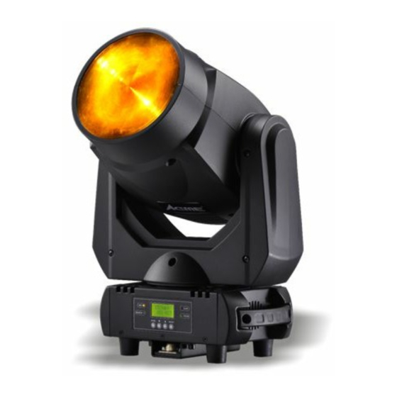
Specification: Power Voltage: AC 100~240V, 50/60Hz Power Consumption: 130W Light Source: 1 x 60W White LED Beam Angle: 6° Fuse: T 3.15A Dimension: 292 x 185 x 461mm Weight: 7.5Kgs 3. How To Set The Unit 3.1 Rear Panel... - Page 6 1. LED: DMX input present MASTER Master Mode SLAVE Slave Mode SOUND Flashing Sound activation 2. Function Display: Show the various menus and the selected functions; 3. Button: MENU To select the programming functions DOWN To go backward in the selected functions To go forward in the selected functions ENTER To confirm the selected functions...
-
Page 7: Main Function
3.2 Main Function To select any functions, press the MENU button until the required function is showing on the display. Select the function by pressing the ENTER button and the display will blink. Use the DOWN and UP button to change the mode. Once the required mode has been selected, press the ENTER button to setup to go back to the functions without any changes press the MENU button again. - Page 9 DMX Address To select the DMX Address, press the ENTER button to show the DMX ADDRESS on the display. Use the DOWN/UP button to adjust the address from 001 to 512. Once the address has been selected, press the ENTER button to setup, to go back to the functions without any changes press the MENU button again.
- Page 10 press the ENTER button to setup, to go back to the functions without any change press the MENU button again. Hold and press the MENU button about one second or wait for one minute to exit the menu mode. Black Out To select the Black Out, press the ENTER button to show the BLACK OUT on the display.
- Page 11 Tilt Inverse To select he Tilt Inverse, press the ENTER button to show the TILT INVERSE on the display. Use the DOWN and UP button to select the Yes (tilt inversion) or No (normal) mode. Once the mode has been selected, press the ENTER button to setup, to go back to the functions without any change press the MENU button again.
- Page 12 unit will run a self-test. To go back to the functions press the MENU button again. Hold and press the MENU button about one second or wait for one minute to exit the menu mode. Temp. To select the Temp., press the ENTER button to show the TEMP. on the display and the display will show the temperature of the unit.
-
Page 13: Home Position Adjustment
Function Delay 3S Delay AUTO Defaults: Mostly automatic mode, for non professional users, detailed explanation as followings: Channel Mode 8Chan Split Color Mode No Slave Mode Slave 1 Black Out No ... -
Page 14: How To Control The Unit
PAN OFFSET —Pan home position adjustment To select the Pan Offset, press the ENTER button to show the PAN OFFSET on the display. Use the DOWN and UP button to adjust the value from -127 to 127, press the ENTER button to store. Press the MENU button to exit. -
Page 15: Master/Slave Built In Preprogrammed Function
move all the motors to their ‘home’ position and you may hear some noises for about 20 seconds. After that the unit will be ready to receive DMX signal or run the built in programs. 4.1 Master/Slave Built In Preprogrammed Function By linking the units in master/slave connection, the first unit will control the other units to give an automatic, sound activated, synchronized light show. -
Page 16: Dmx Controller
4.3 DMX Controller Using a universal DMX controller to control the units, you have to set DMX address from 1 to 512 channel so that the units can receive DMX signal. Press the MENU button up to when the DMX Address is showing on the display. Press the ENTER button and the display will blink. -
Page 17: Dmx512 Configuration
5. DMX512 Configuration 8 Channels Mode:... - Page 18 11 Channels Mode:...
-
Page 19: Dmx Connection
6. DMX Connection Unit 1 Unit 2 Unit 3 Unit 4 1. At last unit, the DMX cable has to be terminated with a terminator. Solder a 120 ohm 1/4W resistor between pin 2(DMX-) and pin 3(DMX+) into a 3-pin XLR-plug and plug it in the DMX-output of the last unit. -
Page 20: Troubleshooting
3 pin XLR: Pin 1: GND, Pin 2: Negative signal (-), Pin 3: Positive signal (+) 5 pin XLR: Pin 1: GND, Pin 2: Negative signal (-), Pin 3: Positive signal (+) Pin 4/5: Not used. 7. Troubleshooting Following are a few common problems that may occur during operation. Here are some suggestions for easy troubleshooting: A. -
Page 21: Fixture Cleaning
E. One of the channels is not working well 1. The stepper motor might be damaged or the cable connected to the PCB is broken. 2. The motor’s drive IC on the PCB might be out of condition. 8. Fixture Cleaning The cleaning must be carried out periodically to optimize light output. - Page 23 Declaration of Conformity We declare that our products (lighting equipments) comply with the following specification and bears CE mark in accordance with the provision of the Electromagnetic Compatibility (EMC) Directive 89/336/EEC. EN55103-1: 2009 ; EN55103-2: 2009; EN62471: 2008; EN61000-3-2: 2006 + A1:2009 + A2:2009; EN61000-3-3: 2008. &...
- Page 24 Широкий ассортимент оборудования ACME на www.maxlight.ru Innovation, Quality, Performance...
Need help?
Do you have a question about the LED BEAM 350 and is the answer not in the manual?
Questions and answers