Table of Contents
Advertisement
Quick Links
Advertisement
Table of Contents

Related Manuals for ACME COOLIE 545


Summary of Contents for ACME COOLIE 545
-
Page 2: Table Of Contents
CONTENTS 1. Safety Instructions ....................2 2. Technical Specifications ..................4 3. How To Set The Unit ....................5 3.1 Control Panel ....................5 3.2 Main Function ....................6 4. Control By Universal DMX Controller ..............12 4.1 DMX512 Connection ..................12 4.2 Address Setting .................... -
Page 3: Safety Instructions
1. Safety Instructions Please read the instruction carefully which includes important information about the installation, usage and maintenance. WARNING Please keep this User Guide for future consultation. If you sell the unit to another user, be sure that they also receive this instruction manual. Important: Damages caused by the disregard of this user manual are not subject to warranty. - Page 4 DO NOT touch any wire during operation as there might be a hazard of electric shock. Avoid power wires together twist other cables. In the event of serious operating problem, stop using the unit immediately. Never turn on and off the unit time after time. ...
-
Page 5: Technical Specifications
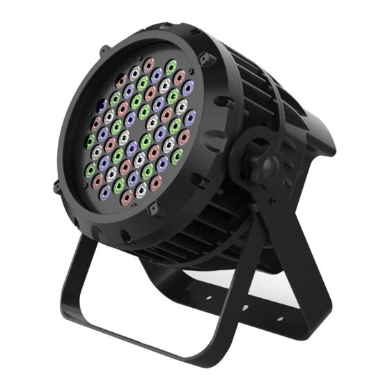
2. Technical Specifications Power Voltage: AC 100~240V, 50/60Hz Power Consumption: 170W Light Source: 54x3W RGBW LED Beam Angles: 19° Control: DMX Channel: 4/5/7 channel Control Mode: DMX, Primary/Secondary Firmware Upgrade: Update via DMX link Construction: Display: LED display Data In/Out Socket: 3-pin XLR socket Protection Rating: IP66 Features: Outstanding color mixing effect... -
Page 6: How To Set The Unit
Photometrics Diagram: 3. How To Set The Unit 3.1 Control Panel 1. POWER IN/OUT: Water proof connectors for power input/output 2. DMX IN/OUT: Water proof connectors for DMX 512 operation, use 3-pin XLR cable to link the units together 3. Display: To show the menu and the selected functions... -
Page 7: Main Function
Button: 4. MENU To select the programming functions 5. DOWN To go forward in the selected functions 6. UP To go backward in the selected functions 7. ENTER To confirm the selected functions 3.2 Main Function Turn on the unit, press the MENU button into menu mode, and press the UP/DOWN button until the required function is shown on the monitor. - Page 9 DMX Address Press the MENU button up to when the is shown on the display. Press ENTER button and the display will blink. Use DOWN and UP button to change the DMX 512 address. Once the address has been selected, press ENTER button to setup or automatically exit menu mode without any change after 30 seconds.
- Page 10 Dimmer Curve Press the MENU button up to when the is shown on the display. Press ENTER button and the display will blink. Use DOWN and UP button to select the (Dimmer Curve 1) … (Dimmer Curve 4). Once select, press ENTER button to store or automatically return to the main functions without any change after 30 seconds.
- Page 11 Invert Display Press the MENU button up to when the is shown on the display. Press ENTER button and the display will blink. Use DOWN and UP button to select the (Normal) or (Invert Display). Once select, press ENTER button to store or automatically return to the main functions without any change after 30 seconds.
- Page 12 Auto Test Press the MENU button up to when the is blinking on the display. Press ENTER button and the unit will run self-test by built-in program. To go back to the functions press the MENU button again. Fixture Temperature Press the MENU button up to when the is blinking on the display.
-
Page 13: Control By Universal Dmx Controller
4. Control By Universal DMX Controller 4.1 DMX512 Connection 1. At last unit, the DMX cable has to be terminated with a terminator. Solder a 120-ohm 1/4W resistor between pin 2(DMX-) and pin 3(DMX+) into a 3-pin XLR-plug and plug it in the DMX-output of the last unit. -
Page 14: Address Setting
4.2 Address Setting Use universal DMX controller to control the units, you have to set DMX address from 1 to 512 channel so that the units can receive DMX signal. Press the MENU button up to when the is showing on the display. Press the ENTER button and the display will blink. - Page 15 5 Channels Mode (Mode 2): Channel Value Function 0-255 0%100% GREEN 0-255 0%100% BLUE 0-255 0%100% WHITE 0-255 0%100% DIMMER 0-255 0%100% 7 Channels Mode (Mode 3): Channel Value Function 0-255 0%100% GREEN 0-255 0%100% BLUE 0-255 0%100% WHITE 0-255 0%100% COLOR WHEEL 8-15...
- Page 16 128-135 PRESET COLOR 16 136-143 PRESET COLOR 17 144-151 PRESET COLOR 18 152-159 PRESET COLOR 19 160-167 PRESET COLOR 20 168-175 PRESET COLOR 21 176-183 PRESET COLOR 22 184-191 PRESET COLOR 23 192-199 PRESET COLOR 24 200-207 PRESET COLOR 25 208-215 PRESET COLOR 26 216-223...
-
Page 17: Troubleshooting
5. Troubleshooting Following are a few common problems that may occur during operation. Here are some suggestions for easy troubleshooting: A. The unit does not work, no light and the fan does not work 1. Check the connect power. 2. Measure the mains voltage on the main connector. 3. - Page 20 Innovation, Quality, Performance...
Need help?
Do you have a question about the COOLIE 545 and is the answer not in the manual?
Questions and answers