
Related Manuals for ACME VB-8-10FC


Summary of Contents for ACME VB-8-10FC
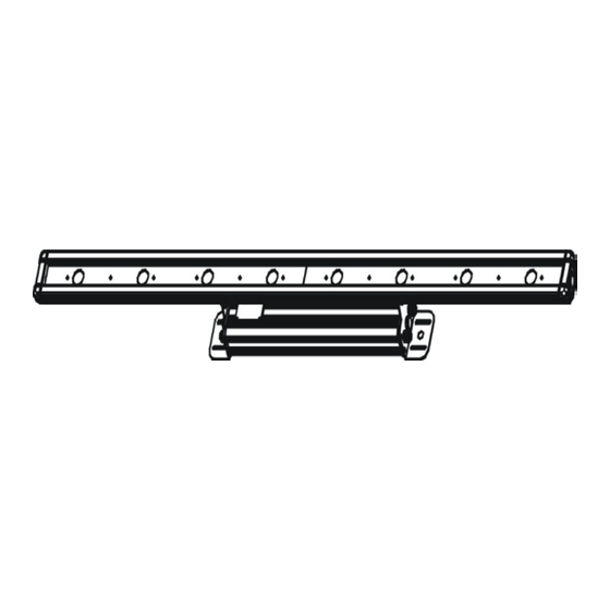
- Page 1 VBar Integral VB-4-10FC VB-8-10FC User Manual Please read the instructions carefully before use...
-
Page 2: Table Of Contents
TABLE OF CONTENTS 1. Safety Instructions 2. Technical Specifications 3. Installation 4. How To Set The Fixture 5. How To Control The Fixture 6. DMX 512 Configuration 7. DMX 512 Connections 8. Troubleshooting 9. Fixture Cleaning... - Page 3 1. Safety Introductions Please read the instructions carefully which includes important information about the installation, operation and maintenance. WARNING Please keep this User Manual for future consultation. If you sell the unit to another user, be sure that they also receive this instruction booklet. ...
-
Page 4: Technical Specifications
Voltage: 100~250V 50/60Hz Power Consumption: 46W LEDs: 4 X 10W(RGBW) IP:66 Dimension: 637 x 79 x 126 mm Weight: 4kg VB-8-10FC Voltage:100~250V 50/60Hz Power Consumption: 89 W LEDs: 8 X 10W(RGBW) IP:66 ... - Page 5 DOWN and UP button until the required one is shown on the display. Select the function by ENTER button and the display will blink. Use DOWN and UP button to change the mode. Once the required mode has been selected, press ENTER button to setup or it will automatically return to the main functions without any change after idling one minute.
- Page 7 DMX 512 Address Setting Press the MENU button up to when the is shown on the display. Pressing ENTER button and the display will blink. Use DOWN and UP button to change the DMX 512 address. Once the address has been selected, press ENTER button to setup (or automatically exit menu mode after idling one minute).
- Page 8 (dimmer) or (strobe). Press ENTER button to confine and use DOWN and UP button to adjust the values. Once select, press the ENTER button to setup (or automatically exit menu mode after idling one minute). Back to the previous functions without any change press MENU button. White Balance Press the MENU button up to when the is shown on the display.
- Page 9 Fixture Hours Press the MENU button up to when the is blinking on the display. Pressing ENTER button and the display will show the number of working hours of the unit. To go back to the main functions press the MENU button. Software version Press the MENU button up to when the is blinking on the display.
- Page 10 Once the address has been selected, press ENTER button to setup (or automatically exit menu mode after idling one minute). To go back to the main functions press the MENU button. Please refer to the following diagram to address your DMX512 channel for the first 4 units.
-
Page 11: Dmx512 Configuration
6. DMX512 Configuration 4 &5 &7 channels mode:... -
Page 12: Dmx512 Connections
7. DMX512 Connections The DMX512 is widely used in intelligent lighting control, with a maximum of 512 channels. Connect the fixture together in a “daisy chain” by XLR plug cable from the output of the fixture to the input of the next fixture. The cable cannot be branched or split to a “Y” cable. -
Page 13: Fixture Cleaning
of the fixture or the previous one. 4. Try to use another DMX controller. 5. Check if the DMX cables run near or run alongside to high voltage cables that may cause damage or interference to DMX interface circuit. C. One of the channel is not working well 1. - Page 14 EC - Declaration of Conformity We declare that our products (lighting equipments) comply with the following specification and bears CE mark in accordance with the provision of the Electromagnetic Compatibility (EMC) Directive 89/336/EEC. EN55014-2: 1997 A1: 2001, EN61000-4-2: 1995; EN61000-4-3: 2002; EN61000-4-4: 1995;...
Need help?
Do you have a question about the VB-8-10FC and is the answer not in the manual?
Questions and answers