Table of Contents
Advertisement
User Manual
Installation
Industrial Ethernet Rail Switch
RS20/RS30-...U Family (unmanaged)
+24V(P1)
3
4
P
LS
DA
5
6
LA learn
SW2
1
7
8
9
10
11
12
LS
DA
13
14
2
15
16
17
18
RS20
FAULT
+24V(P1)
0V 0V
+24V(P2)
LS
DA
P
FAULT
LA learn
ON
1
SW2
LS
DA
1
3
4
LS
DA
5
6
1
7
8
Installation RS20/RS30-...U
Release 03 08/2019
RS20
FAULT
0V 0V
+24V(P2)
LS
DA
FAULT
1
ON
LS
DA
1
LS
DA
1
19
20
LS
DA
21
22
1
23
24
+24V(P1)
3
4
LS
1
5
6
LA learn
DA
7
8
9
10
11
12
13
14
LS
2
15
16
DA
17
18
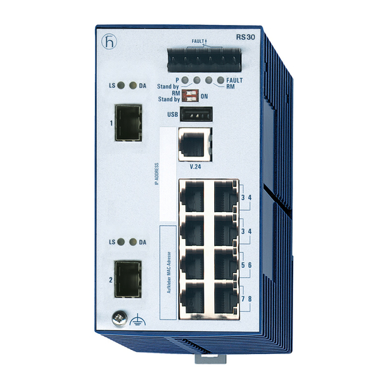
RS30
FAULT
+24V(P1)
0V 0V
+24V(P2)
P
FAULT
LA learn
ON
SW2
3
4
5
6
11
7
8
13
9
10
15
RS30
FAULT
0V 0V
+24V(P2)
P
FAULT
LS
DA
ON
SW2
1
19
20
21
22
LS
DA
23
24
2
25
26
12
14
16
RS30
FAULT
+24V(P1)
0V 0V
+24V(P2)
P
FAULT
LA learn
ON
SW2
3
4
5
6
7
8
9
10
Technical support
https://hirschmann-support.belden.com
Advertisement
Table of Contents

Related Manuals for Belden Hirschmann RS20 U Series


Summary of Contents for Belden Hirschmann RS20 U Series
- Page 1 FAULT LA learn LA learn RS20 RS30 RS30 FAULT FAULT FAULT +24V(P1) 0V 0V +24V(P2) +24V(P1) 0V 0V +24V(P2) +24V(P1) 0V 0V +24V(P2) FAULT FAULT FAULT LA learn LA learn LA learn Installation RS20/RS30-...U Technical support Release 03 08/2019 https://hirschmann-support.belden.com...
- Page 2 The naming of copyrighted trademarks in this manual, even when not specially indicated, should not be taken to mean that these names may be considered as free in the sense of the trademark and tradename protection law and hence that they may be freely used by anyone. ©...
-
Page 3: Table Of Contents
Contents Safety instructions About this Manual Description Description of the device variants 1.1.1 Combination options for RS20/30-...U 1.1.2 Number of ports and media for RS20...U 1.1.3 Number of ports and media for RS30...U Ethernet ports 1.2.1 10/100 Mbit/s twisted pair port 1.2.2 10/100/1000 Mbit/s twisted pair port 1.2.3 100 Mbit/s F/O port 1.2.4 1000 Mbit/s F/O port... - Page 4 Monitoring the ambient air temperature Maintenance and service Disassembly Removing the device Removing an SFP transceiver (optional) Technical data Further support Installation RS20/RS30-...U Release 03 08/2019...
-
Page 5: Safety Instructions
Safety instructions WARNING UNCONTROLLED MACHINE ACTIONS To avoid uncontrolled machine actions caused by data loss, configure all the data transmission devices individually. Before you start any machine which is controlled via data transmission, be sure to complete the configuration of all data transmission devices. Failure to follow these instructions can result in death, serious injury, or equipment damage. - Page 6 Ground the device before connecting any other cables. Observe the maximum values for the contact load of the signal contact. Relevant for North America: The device may only be connected to a Class 2 supply voltage that fulfills the requirements of the National Electrical Code, Table 11(b).
- Page 7 Relevant for use in explosion hazard areas (Hazardous Locations, Class I, Division 2): Relevant for North America for devices certified for Hazardous Locations: Power, input and output (I/O) wiring must be in accordance with Class I, Division 2 wiring methods [Article 501-4(b) of the National Electrical Code, NFPA 70] and in accordance with the authority having jurisdiction.
- Page 8 CONTROL DRAWING: Hazardous Locations Class I, Division 2, Groups A, B ,C ,D NON HAZARDOUS LOCATION HAZARDOUS LOCATION Power supply: USB Port for Auto Configuration (Redundant: P1 P2) Adapter. Type “D”: 9.6Vdc – 60Vdc For maintenance only Fault contacts. Equipment with nonincendive field wiring parameters: V<30V I<90mA L <1,0µH C...
- Page 9 ATEX directive 94/9/EG – specific regulations for safe operation Relevant for RS20/RS30-...U devices when operating in explosive gas atmospheres according to ATEX Directive 94/9 EC, the following applies: List of standards: EN 60079-0:2009 EN 60079-15:2010 Certificate No.: DEKRA 11ATEX0139 X. ...
- Page 10 IECEx – Certification Scheme for Explosive Atmospheres For RS20/RS30-...U devices labeled with an IECEx certificate number, the following applies: List of standards: IEC 60079-0:2011 + Corr.2012 + Corr.2013 IEC 60079-15:2010 The equipment shall only be used in an area of not more than pollution degree 2, as defined in IEC 60664-1.
- Page 11 Device casing Only technicians authorized by the manufacturer are permitted to open the housing. Never insert pointed objects (narrow screwdrivers, wires, etc.) into the device or into the connection terminals for electric conductors. Do not touch the connection terminals. ...
- Page 12 CE marking The labeled devices comply with the regulations contained in the following European directive(s): 2011/65/EU and 2015/863/EU (RoHS) Directive of the European Parliament and of the Council on the restriction of the use of certain hazardous substances in electrical and electronic equipment.
- Page 13 Appropriate testing has established that this device fulfills the requirements of a class A digital device in line with part 15 of the FCC regulations. These requirements are designed to provide sufficient protection against interference when the device is being used in a business environment. The device creates and uses high frequencies and can also radiate these frequencies.
-
Page 14: About This Manual
About this Manual The “Installation” user manual contains a device description, safety instructions, a description of the display, and the other information that you need to install the device. The symbols used in this manual have the following meanings: Listing Work step ... -
Page 15: Description
Description You can choose from between a wide range of variants. You have the option to set up your device individually based on different criteria: Number of ports Transmission speed Media type Types of connectors Temperature range ... -
Page 16: Description Of The Device Variants
3 and 4. You have numerous options of combining the device characteristics. You can determine the possible combinations using the configurator which is available in the Belden E-Catalog (www.e-catalog.beldensolutions.com) on the web page of the device. Position Characteristic Ident. - Page 17 Position Characteristic Ident. Ident.2 Property 6 bis 7 Number of 10/100 8 × 10/100 Mbit/s Ethernet Mbit/s ports 9 × 10/100 Mbit/s Ethernet 16 × 10/100 Mbit/s Ethernet 17 × 10/100 Mbit/s Ethernet 24 × 10/100 Mbit/s Ethernet 25 × 10/100 Mbit/s Ethernet 8 and 9 Number of 0 ×...
-
Page 18: Number Of Ports And Media For Rs20...U
1.1.2 Number of ports and media for RS20...U RS20 FAULT +24V(P1) 0V 0V +24V(P2) FAULT LA learn RS20 RS20 FAULT FAULT +24V(P1) 0V 0V +24V(P2) +24V(P1) 0V 0V +24V(P2) FAULT FAULT LA learn LA learn RS20-0800M2M2...D...U RS20-0800M2T1...D...U RS20-0800T1T1...D...U Figure 1: Device variants with 8 * 10/100 Mbit/s ports (RS20-0800...U) 1 –... - Page 19 RS20 FAULT +24V(P1) 0V 0V +24V(P2) FAULT LA learn FAULT RS20 FAULT RS20 +24V(P1) 0V 0V +24V(P2) +24V(P1) 0V 0V +24V(P2) FAULT FAULT LA learn LA learn RS20-1600M2M2...D...U RS20-1600M2T1...D...U RS20-1600T1T1...D...U Figure 2: Device variants with 16 * 10/100 Mbit/s ports (RS20-1600...U) 1 to 5 –...
- Page 20 RS20 RS20 RS20 FAULT FAULT FAULT +24V(P1) 0V 0V +24V(P2) +24V(P1) 0V 0V +24V(P2) +24V(P1) 0V 0V +24V(P2) FAULT FAULT FAULT LA learn LA learn LA learn RS20-2500MMM2...D...U RS20-1700MMM2...D...U RS20-0900MMM2...D...U Figure 4: Device variants with 3 uplink ports (100 Mbit/s) 1 to 4 –...
-
Page 21: Number Of Ports And Media For Rs30...U
1.1.3 Number of ports and media for RS30...U RS30 FAULT +24V(P1) 0V 0V +24V(P2) FAULT LA learn FAULT RS30 FAULT RS30 +24V(P1) 0V 0V +24V(P2) +24V(P1) 0V 0V +24V(P2) FAULT FAULT LA learn LA learn RS30-0802T1T1...D...U RS30-0802O6O6...D...U RS30-0802O6T1...D...U Figure 5: Device variants with 2 * 1000 Mbit/s ports and 8 * 10/100 Mbit/s ports (RS30-0802...U) 1 –... - Page 22 RS30 FAULT +24V(P1) 0V 0V +24V(P2) FAULT LA learn RS30 RS30 FAULT FAULT +24V(P1) 0V 0V +24V(P2) +24V(P1) 0V 0V +24V(P2) FAULT FAULT LA learn LA learn RS30-1602T1T1...D...U RS30-1602O6O6...D...U RS30-1602O6T1...D...U Figure 6: Device variants with 2 * 1000 Mbit/s ports and 16 * 10/100 Mbit/s ports (RS30-1602...U) 1 to 5 –...
-
Page 23: Ethernet Ports
RS30 RS30 RS30 FAULT FAULT FAULT +24V(P1) 0V 0V +24V(P2) +24V(P1) 0V 0V +24V(P2) +24V(P1) 0V 0V +24V(P2) FAULT FAULT FAULT LA learn LA learn LA learn RS30-2402OOZZ...D...U RS30-1602OOZZ...D...U RS30-0802OOZZ...D...U Figure 8: Device variants with 4 uplink ports 1 to 4 – see figure 5 5 –... -
Page 24: Mbit/S Twisted Pair Port
Function Receive path RD− Receive path Transmission path TD− Transmission path 4,5,7,8 — Table 3: Pin assignment of the 10/100 Mbit/ twisted pair port, RJ-45 socket, MDI-X mode 1.2.2 10/100/1000 Mbit/s twisted pair port This port is an RJ45 socket. The 10/100/1000 Mbit/s twisted pair port offers you the ability to connect network components according to the IEEE 802.3 10BASE-T/100BASE- TX/1000BASE-T standard. -
Page 25: Mbit/S F/O Port
1.2.3 100 Mbit/s F/O port In device variants RS20...U, these ports are DSC connectors or ST connectors. In device variants RS30...U, these ports are SFP slots. The 100 Mbit/s F/O port offers you the ability to connect network components according to the IEEE 802.3 100BASE-FX standard. This port supports: ... -
Page 26: Display Elements
Display elements After the supply voltage is switched on, the device performs a self-test. 1.3.1 Device state These LEDs provide information about conditions which affect the operation of the whole device. FAULT Figure 9: Device status LEDs P - Power (green/yellow LED) Glowing green Both supply voltages are on Glowing yellow... -
Page 27: Port State
1.3.2 Port state These LEDs display port-related information. Figure 10: Port status LEDs 1 – Port status LEDs for isolated or single-row RJ45 sockets: one green and one yellow LED per port. 2 – Port status LEDs for double-row RJ45 sockets: one LED per port, glowing/flashing either green or yellow. -
Page 28: Installation
Installation The devices have been developed for practical application in a harsh industrial environment. On delivery, the device is ready for operation. Perform the following steps to install and configure the device: Checking the package contents Installing and grounding the device ... -
Page 29: Installing The Device Onto The Din Rail
2.2.1 Installing the device onto the DIN rail Verify that the device maintains the minimum clearing in order to meet the climatic conditions: Top and bottom device side: 3.94 in (10 cm) Left and right device side: 0.79 in (2 cm) To mount the device onto a horizontally mounted 35 mm DIN rail according to DIN EN 60715, proceed as follows: ... -
Page 30: Adjust Dip Switch Settings
Proceed as follows: Remove the protective cap from the SFP transceiver. Push the SFP transceiver with the lock closed into the slot until it latches Adjust DIP switch settings The 2-pin DIP switch on the front panel of the device gives you the following options: LA learn Figure 11: 2-pin DIP switch... -
Page 31: Connecting The Terminal Block
Connecting the terminal block WARNING ELECTRIC SHOCK Connect only a supply voltage that corresponds to the type plate of your device. Never insert sharp objects (small screwdrivers, wires, etc.) into the connection terminals for electric conductors, and do not touch the terminals. Observe the maximum values for the contact load of the signal contact. -
Page 32: Fault" Signal Contact
2.6.2 “FAULT” signal contact The signal contact (“FAULT”, for pin assignment of terminal block, see figure 12) monitors the functioning of the device, thus enabling remote diagnostics. The potential-free signal contact (relay contact, closed circuit) reports through a break in contact: ... -
Page 33: Filling Out The Inscription Label
When using copper cables, provide a sufficient separation between the power supply cables and the data cables. Ideally, install the cables in separate cable channels. Used shielded cables (SF/UTP cables as per ISO/IEC 11801:2002). Connect the data cables according to your requirements. For further information see “Description of the device variants”... - Page 34 Monitoring the ambient air temperature Operate the device below the specified maximum ambient air temperature exclusively. See “General technical data” on page 38. The ambient air temperature is the temperature of the air at a distance of 2 in (5 cm) from the device. It depends on the installation conditions of the device, e.g.
- Page 35 Maintenance and service When designing this device, Hirschmann largely avoided using high-wear parts. The parts subject to wear and tear are dimensioned to last longer than the lifetime of the product when it is operated normally. Operate this device according to the specifications. ...
- Page 36 Disassembly Removing the device WARNING ELECTRIC SHOCK Disconnect the grounding only after disconnecting all other cables. Failure to follow these instructions can result in death, serious injury, or equipment damage. Proceed as follows: Disconnect the data cables. Disable the supply voltage. ...
- Page 37 Removing an SFP transceiver (optional) Proceed as follows: Pull the SFP transceiver out of the slot by means of the opened lock. Close the SFP transceiver with the protective cap. Installation RS20/RS30-...U Release 03 08/2019...
- Page 38 Technical data General technical data Dimensions RS20-08..., RS20-09..., RS30-0802 2.91 in. × 5.16 in. × 4.37 in. (74 mm × W × H × D RS20-16..., RS20-17..., RS30-1602 131 mm × 111 mm) RS20-24..., RS20-25..., RS30-2402 4.33 in. × 5.16 in. × 4.37 in. (110 mm ×...
- Page 39 Dimension drawings inch 2.84 4.17 0.55 Figure 14: Dimensions of device variants RS20...U/RS30...U with 8 to max. 10 ports inch 4.17 0.55 4.33 Figure 15: Dimensions of device variants RS20...U/RS30...U with 16 to max. 26 ports Installation RS20/RS30-...U Release 03 08/2019...
- Page 40 EMC and immunity EMC compliance – IEC/EN 61000-6-2:2005 EMI TYPE tests, test acc. to: IEC/EN 61000-4-2 Electrostatic discharge Contact discharge 4 kV 8 kV 8 kV Air discharge 8 kV 15 kV 15 kV IEC/EN 61000-4-3 Electromagnetic field 80 MHz ... 3000 MHz 10 V/m 20 V/m 20 V/m...
- Page 41 Network range Note: The line lengths specified for the transceivers apply for the respective fiber data (fiber attenuation and BLP/dispersion). Product Wave Fiber System Example Fiber code length attenuatio for F/O attenuatio dispersion M-SFP-... line length -SX/LC... MM 850 nm 50/125 µm 0-7.5 dB 0-550 m...
- Page 42 Product Wave Fiber System Example Fiber BLP/ code length attenuatio for F/O line attenuation dispersion M-FAST- length SFP-... -MM/LC... MM 1310 nm 50/125 µm 0-8 dB 0-5 km 1.0 dB/km 800 MHz×km -MM/LC... MM 1310 nm 62.5/125 µm 0-11 dB 0-4 km 1.0 dB/km 500 MHz×km...
- Page 43 Device name Device model Maximum Power output power consumption RS30-1602-... 2xTX port 13.0 W 44.4 Btu (IT)/h RS30-1602-... 1xFX port, 1xTX port 12.7 W 43.4 Btu (IT)/h RS30-1602-... 2xFX port 12.4 W 42.4 Btu (IT)/h RS30-2402-... 2xTX port 15.7 W 53.6 Btu (IT)/h RS30-2402-...
- Page 44 Accessories Note that products recommended as accessories may have different characteristics to those of the device, which may limit the application range of the overall system. For example, if you add an accessory with IP 20 to a device with IP 65, the IP of the overall system is reduced to 20. Gigabit Ethernet SFP transceiver Order number M-SFP-TX/RJ45...
- Page 45 Fast Ethernet SFP transceiver Order number M-FAST SFP-MM/LC 943 865-001 M-FAST SFP-MM/LC EEC 943 945-001 M-FAST SFP-SM/LC 943 866-001 M-FAST SFP-SM/LC EEC 943 946-001 M-FAST SFP-SM+/LC 943 867-001 M-FAST SFP-SM+/LC EEC 943 947-001 M-FAST SFP-LH/LC 943 868-001 M-FAST SFP-LH/LC EEC 943 948-001 Other accessories Order number...
- Page 46 Underlying technical standards Standard EN 50121-4 Railway applications - EMC - emitted interference and interference immunity for signal and telecommunication systems EN 55032 Electromagnetic compatibility of multimedia equipment – Emission Requirements IEC/EN 60079-15 Explosive atmospheres – Part 15: Equipment protection by type of protection “n”...
- Page 47 You find the addresses of our partners on the Internet at http://www.hirschmann.com. A list of local telephone numbers and email addresses for technical support directly from Hirschmann is available at https://hirschmann-support.belden.com. This site also includes a free of charge knowledge base and a software download section. Hirschmann Competence Center...
Need help?
Do you have a question about the Hirschmann RS20 U Series and is the answer not in the manual?
Questions and answers