S&C TripSaver II Installation, Operation, And Configuration
Cutout-mounted recloser
Hide thumbs
Also See for TripSaver II:
- Manual (132 pages) ,
- Installation, operation, and configuration (89 pages) ,
- Installation and operation manual (36 pages)
Table of Contents
Advertisement
Quick Links
TripSaver
II Cutout-Mounted Recloser
®
Outdoor Distribution (15.5 kV, 25 kV)
Installation, Operation, and Configuration
Table of Contents
Section
Qualified Persons . . . . . . . . . . . . . . . . . . . . . . . . . . . 2
Read this Instruction Sheet . . . . . . . . . . . . . . . . . . . 2
Retain this Instruction Sheet . . . . . . . . . . . . . . . . . . . 2
Video . . . . . . . . . . . . . . . . . . . . . . . . . . . . . . . . . . . . . 2
Proper Application . . . . . . . . . . . . . . . . . . . . . . . . . . 2
Warranty . . . . . . . . . . . . . . . . . . . . . . . . . . . . . . . . . . 2
Understanding Safety-Alert Messages . . . . . . . . . . . 3
Following Safety Instructions . . . . . . . . . . . . . . . . . . 3
Replacement Instructions and Labels . . . . . . . . . . . 3
Location of Safety Labels . . . . . . . . . . . . . . . . . . . . . 4
. . . . . . . . . . . . . . . . . . . . . . . . . 5
Packing . . . . . . . . . . . . . . . . . . . . . . . . . . . . . . . . . . . 6
Inspection . . . . . . . . . . . . . . . . . . . . . . . . . . . . . . . . . 6
Handling . . . . . . . . . . . . . . . . . . . . . . . . . . . . . . . . . . 6
Storage . . . . . . . . . . . . . . . . . . . . . . . . . . . . . . . . . . . 6
Returning . . . . . . . . . . . . . . . . . . . . . . . . . . . . . . . . . 6
Powering the Communications Gateway . . . . . . . . . 9
Securing the Communications Gateway . . . . . . . . . 9
Installing a New Radio . . . . . . . . . . . . . . . . . . . . . . .10
Replacing a Radio . . . . . . . . . . . . . . . . . . . . . . . . . .11
Installing a New Battery . . . . . . . . . . . . . . . . . . . . . .12
Replacing a Battery . . . . . . . . . . . . . . . . . . . . . . . . .13
Installing Local Antenna 904-002450-02 . . . . . . . . .16
Replacing a Local Antenna . . . . . . . . . . . . . . . . . . . .16
June 1, 2021
© S&C Electric Company 2021, all rights reserved
Page
. . . . . . . . . . . . . . . . . . . 7
TripSaver
II Communications via Gateway
®
using the IEC 60870-5-104 Protocol
Section
Software User's Guide . . . . . . . . . . . . . . . . . . . . . . .17
Enabling IEC 60870-5-104 Communication
Protocol in the Communications Gateway . . . . . .19
General Status . . . . . . . . . . . . . . . . . . . . . . . . . . . . 20
Gateway Settings . . . . . . . . . . . . . . . . . . . . . . . . . . .21
Device Management . . . . . . . . . . . . . . . . . . . . . . . . 37
®
Software . . . . . . . . . . . . . . . . . . . . . . . . . . . . . . . . . 38
Remote Drop Open . . . . . . . . . . . . . . . . . . . . . . . . . 40
Gang/Local Operation . . . . . . . . . . . . . . . . . . . . . . 42
User Roles . . . . . . . . . . . . . . . . . . . . . . . . . . . . . . . 46
IEC 104 Setpoints . . . . . . . . . . . . . . . . . . . . . . . . . . .47
IEC104 Controlling Station . . . . . . . . . . . . . . . . . . . 53
IEC104 Controlled Station . . . . . . . . . . . . . . . . . . . 53
Security Settings . . . . . . . . . . . . . . . . . . . . . . . . . . . 54
Profile . . . . . . . . . . . . . . . . . . . . . . . . . . . . . . . . . . . 58
Diagnostics . . . . . . . . . . . . . . . . . . . . . . . . . . . . . . . 58
for Use with the Communications Gateway
with Firmware Version 1 .9 or 1 .8 . . . . . . . . . . . . 60
Version 1 .6 or 1 .7 Installed on the Utility Pole
and Powered by Line Current . . . . . . . . . . . . . . . .61
Signal Interference . . . . . . . . . . . . . . . . . . . . . . . . . 63
Appendix A
Interface Pinouts . . . . . . . . . . . . . . . . . . . . . . . . . . . 65
Power System Diagram . . . . . . . . . . . . . . . . . . . . . 66
Understanding the Radio Mode . . . . . . . . . . . . . . . 66
Appendix B
. . . . . . . . . . . . . . . . 64
. . . . . . . . . . . . . . . . . . . . . 68
Instruction Sheet 461-519
Page
Advertisement
Table of Contents

Subscribe to Our Youtube Channel
Related Manuals for S&C TripSaver II


Summary of Contents for S&C TripSaver II
-
Page 1: Table Of Contents
. . . . . . . . . . . . . . . . . . . 7 Field Pairing a TripSaver II Recloser with Firmware Mounting the Communications Gateway to a Pole . -
Page 2: Introduction
Sheet Video A video of the how to pair a communications gateway with a TripSaver II Cutout-Mounted Recloser is available at sandc.com/GatewayPairing-video. The goal of the video is to provide a clear and simple visual reference. In no way is the video meant as a complete replacement of these written instructions. -
Page 3: Safety Information
Understanding Several types of safety-alert messages may appear throughout this instruction sheet and on labels and tags attached to your TripSaver II Communications Gateway. Familiarize yourself with these Safety-Alert types of messages and the importance of these various signal words:... -
Page 4: Location Of Safety Labels
Safety Information Location of Safety Labels (Not Shown) Reorder Information for Safety Labels Location Safety Alert Message Description Part Number CAUTION 180-000070-00 Rev A This control is connected to electrical distribution equipment . . . CAUTION 180-002533-01 Risk of electric shock . . . CAUTION 180-002577-01 Earth Ground... -
Page 5: Safety Precautions
Safety Precautions DANGER The TripSaver II Communications via Gateway system connects to a 120/240-Vac source. Failure to observe these precautions will result in serious personal injury or death. Some of these precautions may differ from your company’s operating procedures and rules . Where a discrepancy exists, follow your company’s operating procedures and rules . -
Page 6: Shipping And Handling
. The communications gateway weighs about 20 lbs . (9 kg); follow proper lifting techniques to avoid minor injury . TripSaver II Communications Gateways are shipped on pallets banded with plastic wrap. Storage This packaging is designed to protect the communications gateway from freight damage. -
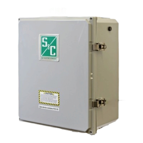
Page 7: Mounting, Powering, And Securing The Communications Gateway
Mounting, Powering, and Securing the Communications Gateway Antenna Radio PS/Battery Board Gateway Controller Battery Module Module Ac line fuse Ac line fuse Ground wire Figure 1. The TripSaver II Communications Gateway. S&C Instruction Sheet 461-519... -
Page 8: Mounting The Communications Gateway To A Pole
The communications gateway antenna is directional. The communications gateway should be mounted ideally no more than 30 feet (9.1 m) below the TripSaver II reclosers to which it will be paired. There should be an unobstructed line of sight between the gateway antenna and the LCD screen of each TripSaver II recloser. -
Page 9: Powering The Communications Gateway
Mounting, Powering, and Securing the Communications Gateway Powering the Follow these steps to power up the communications gateway: Communications Remove the red protection cap attached to the power-connection terminal at STEP 1. Gateway the bottom of the communications gateway. ● STEP 2. -
Page 10: Installing And Replacing A Radio
Installing and Replacing a Radio Installing a New Radio A radio providing fi eld-area network capability for SCADA applications, if specifi ed, is furnished factory-installed in the communications gateway. Alternately, the customer may install a user-furnished radio. See Figure 4. Follow these steps to install a radio in the communications gateway: Disconnect the ac power cable connected to the bottom of the gateway and then STEP 1. -
Page 11: Replacing A Radio
Installing and Replacing a Radio Attach the antenna connector to the user-furnished radio. If using the standard STEP 4. S&C-provided antenna, the applicable leads are LTE 1 (890- to 960-MHz/1710- to 2700-MHz bands) and LTE 2 (diversity). If using a remote antenna, use the leads from the surge-suppressor connector. -
Page 12: Installing And Replacing A Backup Battery
Installing and Replacing a Backup Battery Installing a New A backup battery to support the loss of control power and the Gang Operation feature, if specifi ed, is furnished factory-installed in the communications gateway. For Battery customers who initially choose not to have a backup battery, a backup battery system kit (903-002460-01) can be retrofi tted to the communications gateway. -
Page 13: Replacing A Battery
Installing and Replacing a Backup Battery Replacing a Battery Follow these steps to replace a battery in the communications gateway: STEP 1. Disconnect the ac power cable connected to the bottom of the gateway (See Figure 2 on page 8) and then disconnect the ac line fuse located at the lower right corner of the gateway box. -
Page 14: Installing Remote Antenna Kits
Installing Remote Antenna Kits Installing Remote The 403- to 470-MHz, 2-dBi antenna kit includes an omnidirectional antenna with an N-male connector, pole mounting and bracket BM-1009, two pieces of shrink tubing, Antenna Kit grounding kits for the LMR-400, and a weather-resistant cable tie. Also available are 903-002702-02/01 40-foot (12.2-m) or 60-foot (18.3-m) coaxial cable-length options. -
Page 15: Installing Remote Antenna Kit 903-002701-01/02
Installing Remote Antenna Kits Installing Remote The 890- to 960-MHz, 10-dBi antenna includes an omnidirectional Yagi antenna, a pole-mounted single antenna arm with 30-foot (9.1-m) or 50-foot (15.2-m) coaxial cable, Antenna Kit and N-type male connectors on both ends. The customer must provide 1.375-inch (35-mm) 903-002701-01/02 OD pipe for the antenna. -
Page 16: Installing And Replacing A Local Antenna
Installing and Replacing a Local Antenna Installing Local The 403- to 470-MHz, 2-dBi antenna includes an omnidirectional antenna with an N-type male connector. Antenna 904-002450-02 STEP 1. Remove the protection cap attached to the antenna connector terminal at the bottom of the communications gateway box. STEP 2. -
Page 17: Configuring The Communications Gateway
Confi guring the Communications Gateway Software User’s Logging on to the Communications Gateway Guide The communications gateway is accessed via a Web browser interface. Connect a personal computer (PC) with a CAT5 Ethernet cable to the communications gateway’s Ethernet Port 1. - Page 18 Configuring the Communications Gateway Note: If the interface indicates “media disconnected,” this is an indication the Ethernet connection between the host PC and the communications gateway is not functional, and it should be investigated. NOTICE Because the end user can change the IP address range, or even disable DHCP completely and change the communications gateway to a static IP, it is important to make a note of any IP settings changes .
-
Page 19: Protocol In The Communications Gateway
Configuring the Communications Gateway Figure 12. The Profile screen for changing the default password. After a successful login, the browser will open to the communications gateway General Status screen with an application Navigation menu on the left side of the screen. The Navigation menu will remain visible for all subordinate menu interface screens. -
Page 20: General Status
Configuring the Communications Gateway A success message will display, and the IEC104 Setpoints, IEC104 Controlling Station, and IEC104 Controlled Station menu items will show on the menu bar. See Figure 14. Figure 14. IEC104 Enabled. General Status NOTICE Simultaneous access to the Web-user interface by multiple users is not officially supported . -
Page 21: Gateway Settings
Configuring the Communications Gateway Gateway Settings The Gateway Settings screen contains the “General Gateway Settings,” “Ethernet 1 (LAN),” “Ethernet 2 (WAN),” “SCADA Protocol,” “Time Synchronization,” “Gateway Configuration,” “Firmware Upgrade,” “Reboot Gateway,” and “Ping Station” panels. Note: For all field edits within each menu, the Save button must be clicked on for field modifications to occur. - Page 22 Confi guring the Communications Gateway General Gateway Settings The “General Gateway Settings” panel contains the Gateway Name fi eld that allows unique naming of the communications gateway. Enter a user-defined name for the communications gateway and click on the Save button.
- Page 23 Confi guring the Communications Gateway Ethernet 2 (WAN) The “Ethernet 2 (WAN)” panel defi nes the IP addressing for the communications gateway’s Ethernet Port 2 and subsequent network linkage and settings respective to the customer’s legacy back-haul WAN network. See Figure 18. Note: The use of these fi elds is for WANs that use Ethernet as a back-haul transport protocol.
- Page 24 Confi guring the Communications Gateway Note: For both the DHCP On and Off states, the Ping Response toggle button when toggled to the On position will make the gateway responsive to a ping command. This toggle button is in the Off position by default. Scroll up and click on the Save button to make changes.
- Page 25 Configuring the Communications Gateway Time Synchronization The communications gateway supports three primary methods of time synchronization: “GPS only,” “SCADA only,” and “GPS Primary, SCADA backup.” Select the desired option from the Time Synchronization Source dropdown menu and click on the Save button. The communications gateway also supports a fourth method of time synchronization.
- Page 26 Configuring the Communications Gateway XML File Description The XML file format is split into two sections. The first section is encapsulated by <ConfigDB> and <configuration> tags. Each item in this section is a simple name/value pair, for example: <ConfigDB> <configuration> <item value=”True”...
- Page 27 Gang/Local Boolean True or False tab for each TripSaver II recloser . When set to “False,” the Gang Operation feature will not operate . The maximum number of times the gateway will retry a Gang operation after timing out gangOperationMaxRetries in its initial attempt .
- Page 28 Configuring the Communications Gateway The second section in the XML file format is encapsulated by <IEC104> tags. This contains all the IEC104 related settings, for example: <IEC104> <SinglePoints> <singlepoint eventsEnabled=”1” periodicReportingEnabled=”1” interrogationGroup=”6” ioa=”10000” codeDescription=”9”/> <singlepoint eventsEnabled=”0” periodicReportingEnabled=”1” interrogationGroup=”0” ioa=”10001” codeDescription=”4”/> </SinglePoints>...
- Page 29 Configuring the Communications Gateway Table 2. Import and Export Settings Configuration - Continued Parameter Group Attribute Description Data Range of Type Value Information Object Address for this setpoint . Integer value 20000 to Integer starting at 20000 . 29999 Valid values Integer value referring to the setpoint code description defined codeDescription Integer...
- Page 30 Confi guring the Communications Gateway Import Configuration Follow these steps to complete the Import Confi guration function. See Figures 23 and 24. STEP 1. Under the “Gateway Confi guration” panel, click on the Import Confi guration button. A dialog box opens. Click on the Browse button, which invokes a Windows fi le navigation box.
- Page 31 Confi guring the Communications Gateway Export Configuration Follow these steps to complete the Export Confi guration function. See Figures 25 and 26. On the “Gateway Confi guration” panel, click on the Export Confi guration STEP 1. button. A dialog box opens with a suggested fi lename for the exported confi guration.
- Page 32 Confi guring the Communications Gateway Firmware Upgrade The “Firmware Upgrade” panel enables the loading of fi rmware versions onto the communications gateway. See Figure 27. Follow these steps to perform a fi rmware upgrade: STEP 1. Download the fi rmware fi le. Firmware fi les can be found in the S&C Customer Portal at sandc.com/en/support/sc-customer-portal/.
- Page 33 Confi guring the Communications Gateway STEP 4. The fi le loads to the communications gateway. After the upload completes, the gateway will confi rm that the upload was successful. See Figures 29 and 30. Figure 29. The Firmware Upload progress bar. Figure 30.
- Page 34 Confi guring the Communications Gateway After the fi le is verifi ed, a notifi cation will appear. Click on the OK button to STEP 6. dismiss this window. The Upgrade button will become active. See Figure 32. Figure 32. The dialog box showing the firmware-verification process is complete. STEP 7.
- Page 35 Confi guring the Communications Gateway STEP 8. When the gateway has completed processing the upgrade, it will display a notifi cation. See Figure 35. When the user clicks on the OK button on this notifi cation, the browser will display a screen indicating the gateway is unavailable while it reboots.
- Page 36 Confi guring the Communications Gateway Reboot Gateway The red Reboot button enables the user to restart the communications gateway. See Figure 36. When selected, a dialog box opens for confi rmation of the Reboot command. After the user clicks on the OK button, the user interface will display the Gateway Unavailable screen.
-
Page 37: Device Management
Gateway” section on page 60 for a walk-through of the pairing process . To add a TripSaver II recloser, click on the Add TripSaver II button on the top right of the screen. A pop-up dialogue box will open. Enter the recloser’s transceiver ID and the desired device name. -
Page 38: Tripsaver ® Ii Service Center Configuration
ID, link status, and RSSI are displayed. A TripSaver II recloser may be changed or removed by clicking on the Edit or Remove button. Clicking on the Identify button will cause the TripSaver II recloser to update its LCD screen to all blue, and then all white, and repeat. - Page 39 Select the desired recloser and click on the Connect button. The Identify button can be used to help identify a TripSaver II recloser. It will cycle the recloser’s LCD screen to solid blue, and then back again. See Figure 43.
-
Page 40: Remote Drop Open
Confi guring the Communications Gateway Remote Drop Open TripSaver II reclosers supplied with the 30-second option (-O) and fi rmware version 1.8 or 1.9, and ordered with the Remote Drop Open option (“-D”) factory-enabled, can be confi gured using the Remote Drop Open settings to operate when issued an IEC104 command. - Page 41 Confi guring the Communications Gateway After the Remote Drop Open feature is activated in the TripSaver II recloser and in the communications gateway by toggling the Activated in TSII and Activated in GW toggle buttons to the On position, click on the Save button to save the settings. See Figure 45.
-
Page 42: Gang/Local Operation
Configuring the Communications Gateway When a TripSaver II recloser that does not have the Remote Drop Open option (“-D”) factory-enabled is paired with the communications gateway, the Factory Enabled in TSII setting will show a grey “NO” label, and the two Activation Status indicators will also show a grey “NO”... - Page 43 Command” column. This single-unit operation feature works regardless of whether the TripSaver II recloser is configured to work in a gang. For this feature to work, the Receive Local Drop Open setting must be enabled in both the gateway and the TripSaver II recloser by toggling the appropriate buttons to the On position.
- Page 44 Confi guring the Communications Gateway To enable a TripSaver II recloser to be an initiator of a Gang operation, one or more of the Initiate Gang Operation toggle buttons must be toggled to the On position. The three initiator buttons are Permanent Fault, Local Manual Open (LMO), or Orientation Change.
- Page 45 Enter a walkaway time long enough to give any personnel underneath the TripSaver II reclosers enough time to walk away . Do not stand underneath the TripSaver II reclosers during a Gang operation . Failure to walk away could result in severe personal injury .
-
Page 46: User Roles
The purpose of the User Roles menu is for adding users and corresponding access privileges. The types of user roles include Admin, Gateway User, TripSaver II User, and Technician. The addition of a user is initiated by clicking on the Add User button. A dialog box will open with the required User, Password, and Confi rm Password fi elds, and a drop-down box to select user type. -
Page 47: Iec 104 Setpoints
Allowed Allowed Allowed Allowed configuration Install firmware Allowed Blocked Blocked Blocked Add/Update/Remove Device Allowed Allowed Allowed Blocked TripSaver II recloser Management buttons Remote Drop Open Allowed Blocked Blocked Blocked Configure Gang Gang/Local Allowed Allowed Blocked Blocked Operation Operation settings Perform Gang Trip/... - Page 48 Code Description field in line with the respective IOA field. A drop-down dialog box will appear with code definitions for all TripSaver II reclosers paired with the com- munications gateway. See Figure 55. When a code definition has been chosen, select the Check Mark icon to finalize it.
- Page 49 Description field in line with the respective IOA field. A drop-down dialog box will appear with code definitions for all TripSaver II reclosers paired with the communica- tions gateway. See Figure 56. When a code definition has been chosen, select the Check Mark icon to finalize it.
- Page 50 Code Description field in line with the respective IOA field. A drop-down dialog box will appear with code definitions for all TripSaver II reclosers paired with the com- munications gateway. See Figure 57. When a code definition has been chosen, select the Check Mark icon to finalize it.
- Page 51 Code Description field in line with the respective IOA field. A drop-down dialog box will appear with code definitions for all TripSaver II reclosers paired with the com- munications gateway. See Figure 58. When a code definition has been chosen, select the Check Mark icon to finalize it.
- Page 52 Code Description field in line with the respective IOA field. A drop-down dialog box will appear with code definitions for all TripSaver II reclosers paired with the com- munications gateway. See Figure 59. When a code definition has been chosen, select the Check Mark icon to finalize it.
-
Page 53: Iec104 Controlling Station
Confi guring the Communications Gateway IEC104 Controlling The purpose of the IEC104 Controlling Station screen is to update the IP settings for connecting to the IEC104 controlling station. The gateway will only allow connections Station from a confi gured IP address. To enable communication with the controlling station, IP Address #1 must be set to a valid IPv4 address. -
Page 54: Security Settings
Configuring the Communications Gateway Cyclic/Periodic Reporting interval (Seconds): This is the time between IEC104 cyclic/periodic reports initiated by the gateway. (Range: 15 to 3600) Max Allowable Command Delay: This defines the maximum allowed difference between the timestamp provided in an IEC 104 command with time and the present system time. - Page 55 Configuring the Communications Gateway OpenVPN Configuration This setting allows the administrator to create an OpenVPN tunnel to encapsulate IP packets from the local interface to the remote OpenVPN server. As with the tunnel configuration above, select the Open VPN option from the drop- down menu.
- Page 56 • The Drop Open commands on the Gang/Local Operation screen will not be available . • The Enable command on the TripSaver II Service Center Configuration Software screen will not be available . Follow these steps to enable the Remote Web Access feature: In the Profi le tab, the gateway admin password must be changed locally from STEP 1.
- Page 57 Confi guring the Communications Gateway See Figure 65. On the IEC104 Setpoints screen, a Single Command or STEP 3. Double Command point must be confi gured with a code description: “1: Communication Gateway remote web user interface switch.” Figure 65. The remote Web access command point. See Figure 66 on page 58.
-
Page 58: Profile
Confi guring the Communications Gateway From the IEC 104 controlling station, send a single command or double STEP 6. command to the information object address (IOA) confi gured in Step 3. See Figure 65 on page 57. At the IEC 104 controlling station, check the Single Point Information or Double STEP 7. - Page 59 Confi guring the Communications Gateway When any of the Retrieve buttons are selected, a dialog box opens with a Download and Cancel button. See Figure 69. After clicking the Download button, a completion bar will display. Figure 69. The Diagnostic Log download dialog box. If the Download button is clicked, a notifi cation of fi le download completion appears, and the log fi le will be saved in the computer’s Download fi le folder.
-
Page 60: Commissioning (Pairing) A Tripsaver Ii Recloser
Pairing the reclosers one at a time is the fastest method to pair a TripSaver II recloser and a communications gateway. TripSaver II reclosers must be furnished with the Extended Open Interval option, which allows up to a 30-second open interval between reclose operations. -
Page 61: Field Pairing A Tripsaver Ii Recloser With Firmware
1.8 or later, there may be a need to pair a TripSaver II recloser using an older version of the firmware with a communications gateway. For TripSaver II reclosers furnished with firmware version 1.6 or 1.7, pairing can only be performed at the installation site with the... - Page 62 Mounted Recloser, Outdoor Distribution (15 kV and 25 kV): Installation and Operation,” and power it via line current. Install the communications gateway no more than 30 feet (9.1 m) from the TripSaver II recloser(s) to be paired. Connect the communications gateway to ac power.
-
Page 63: Troubleshooting
Difficulties in pairing a TripSaver II recloser with a communications gateway are usually caused by signal interference. Remember, the communications gateway should be no more than 100 feet (30.5 m) away from the TripSaver II recloser and should have an unobstructed view of the recloser. The communications gateway antenna is directional, and the TripSaver II reclosers must be installed above the communications gateway, ideally on the same pole. -
Page 64: Quick Installation Checklist
Quick Installation Checklist Pre-Installation □ Examine the shipment(s) and make sure it includes: • The communications gateway • Mounting hardware for securing the gateway to the pole • An ac power cable • Make sure the recloser uses firmware v1.6 or later for Extended Open Interval functionality. -
Page 65: Interface Pinouts
Appendix A Interface Pinouts The RS-232 port of the gateway controller module (green box) is configured as data-terminal equipment. See Table 4. Table 4. Gateway Controller Module RS-232 Interface Pinout Function Description No Connection RX from Radio RS-232 Receive TX to Radio RS-232 Transmit No Connection TX to Radio GND... -
Page 66: Power System Diagram
“corded” power module (power module with ac adapter and extension cord) to the base of the TripSaver II recloser . The corded power module is ONLY intended to be used for setup and data collection when the TripSaver II recloser is de-energized and removed from the utility pole . - Page 67 Upon powering up, a TripSaver II recloser will identify itself to the communications gateway and use a secure algorithm to establish an authenticated and encrypted con- nection to the gateway. The gateway operator must then explicitly add the TripSaver II recloser to the local network via the secure Web-user interface.
-
Page 68: Regulatory Information
Appendix B Regulatory Information This document contains statements that are required for compliance with the rules and policies of various national and international regulatory agencies. The information is current as of the date of this publication but may be subject to change without notice. For the most recent version of this Instruction Manual with the most up to date regulatory information, visit www.sandc.com.
Need help?
Do you have a question about the TripSaver II and is the answer not in the manual?
Questions and answers