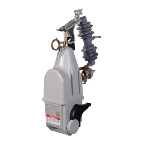
S&C TripSaver II Manual
Cutout-mounted recloser
Hide thumbs
Also See for TripSaver II:
- Manual (132 pages) ,
- Installation, operation, and configuration (89 pages) ,
- Installation and operation manual (36 pages)
Table of Contents
Advertisement
Quick Links
TripSaver
II Cutout-Mounted Recloser
®
Outdoor Distribution (15 kV and 25 kV)
Table of Contents
Section
Qualified Persons . . . . . . . . . . . . . . . . . . . . . . . . . . . 2
Read This Instruction Sheet . . . . . . . . . . . . . . . . . . . 2
Retain This Instruction Sheet. . . . . . . . . . . . . . . . . . . 2
Proper Application . . . . . . . . . . . . . . . . . . . . . . . . . . 2
Warranty . . . . . . . . . . . . . . . . . . . . . . . . . . . . . . . . . . 3
End User License Agreement . . . . . . . . . . . . . . . . . . 3
Understanding Safety-Alert Messages . . . . . . . . . . . 4
Following Safety Instructions . . . . . . . . . . . . . . . . . . 4
Replacement Instructions And Labels . . . . . . . . . . . 4
. . . . . . . . . . . . . . . . . . . . . . . . . 5
Packing . . . . . . . . . . . . . . . . . . . . . . . . . . . . . . . . . . . 6
Inspection . . . . . . . . . . . . . . . . . . . . . . . . . . . . . . . . . 7
Handling . . . . . . . . . . . . . . . . . . . . . . . . . . . . . . . . . . 7
Installing TripSaver® II Service
CenterConfiguration Software Version 1.8
Computer Requirements . . . . . . . . . . . . . . . . . . . . . 8
Downloading Software . . . . . . . . . . . . . . . . . . . . . . . 8
Software Installation . . . . . . . . . . . . . . . . . . . . . . . . . 9
Power Supply
Installing the USB Transceiver . . . . . . . . . . . . . . . . .13
Powering Up The Tripsaver Ii Recloser . . . . . . . .13
Transceiver ID
Obtaining The Transceiver Id . . . . . . . . . . . . . . . . . .15
July 13, 2020
© S&C Electric Company 2014-2020, all rights reserved
Protection Setup Using
Service Center Con guration Kit
For Overhead Distribution Systems
Page
Section
Using TripSaver II Service Center Configuration
Software Version 1.8
Launching The Software . . . . . . . . . . . . . . . . . . . . . .17
Reading and Understanding the
Warning Message . . . . . . . . . . . . . . . . . . . . . . . .17
Terminology . . . . . . . . . . . . . . . . . . . . . . . . . . . . . . .17
Overview . . . . . . . . . . . . . . . . . . . . . . . . . . . . . . . . . .18
Menu Bar Functions . . . . . . . . . . . . . . . . . . . . . . . . 23
Additional Information Bar . . . . . . . . . . . . . . . . . . . 39
Entering Data . . . . . . . . . . . . . . . . . . . . . . . . . . . . . 40
Tcc Settings Screen . . . . . . . . . . . . . . . . . . . . . . . 43
Nr Curve Settings Screen . . . . . . . . . . . . . . . . . . . 59
Sectionalizing Settings Screen . . . . . . . . . . . . . . . . 62
Lcd Screen Settings Screen . . . . . . . . . . . . . . . . . 64
Status Screen . . . . . . . . . . . . . . . . . . . . . . . . . . . . . 70
Event Logs Screen . . . . . . . . . . . . . . . . . . . . . . . . . 76
Functional Test Screen . . . . . . . . . . . . . . . . . . . . . . .81
Local Manual Open Settings . . . . . . . . . . . . . . . . . 86
Communication Settings Screen . . . . . . . . . . . . . . 89
R-Nr Functions Screen . . . . . . . . . . . . . . . . . . . . . 92
Gateway Drop Open Screen . . . . . . . . . . . . . . . . . . 93
Dnp Remote Drop Open Screen . . . . . . . . . . . . . . 95
Appendix A
List Of Available Curves . . . . . . . . . . . . . . . . . . . . . 97
Appendix B
Available Screens for "Screens When
Dropped-Open" Selection . . . . . . . . . . . . . . . . . 99
Appendix C
Available Screens to Be Added to the "Display"
Screen Sequence. . . . . . . . . . . . . . . . . . . . . . . .101
Appendix D
Tripsaver Ii Recloser Is In R-Nr Mode . . . . . . .104
Appendix E
Regulatory Information . . . . . . . . . . . . . . . . . . . . . .105
Instruction Sheet 461-504
Page
Advertisement
Table of Contents

Related Manuals for S&C TripSaver II


Summary of Contents for S&C TripSaver II
- Page 1 Assembling the Power Supply and Dropped-Open” Selection ....99 Powering Up the TripSaver II Recloser ..13 Appendix C Transceiver ID Available Screens to Be Added to the “Display”...
- Page 2 Safety Precautions on pages 4 and 5. The latest version of this publication is available online in PDF format at sandc.com/en/support/product-literature/. Retain this This instruction sheet is a permanent part of your TripSaver II Cutout-Mounted Recloser. Designate a location where you can easily retrieve and refer to this publication. Instruction Sheet...
- Page 3 Price Sheet 155. Speci cally, for each con guration kit purchased, the user is entitled to install and use S&C TripSaver II Service Center Con guration Software on no more than two computers at a time.
- Page 4 Understanding Several types of safety-alert messages may appear throughout this instruction sheet and on labels attached to the TripSaver II Cutout-Mounted Recloser or in the TripSaver II Safety-Alert Messages Service Center Con guration Software. Familiarize yourself with these types of messages...
- Page 5 TripSaver II recloser is de-energized and removed from the utility pole. (To provide power to a TripSaver II recloser while it is mounted to the pole, use the cordless power module, S&C catalog number 5954.) Failure to remove the TripSaver II recloser from the utility pole before connecting the corded power module can cause arcing, burns, electric shock, and death.
- Page 6 Shipping and Handling Packing A complete TripSaver II Con guration Kit, which weighs about 4 lbs. (1.8 kg) and works with both 15-kV and 25-kV TripSaver II reclosers, consists of the following items enclosed in a carrying case: Ac adapter...
- Page 7 After a TripSaver II recloser has been configured, always return components to the carrying case for protection. In addition, DO NOT drop a TripSaver II recloser or subject any of its parts to undue stress during configuration or installation. Only remove a TripSaver II recloser from the carton when it is ready for configuration or installation.
- Page 8 • Administrative privileges for software installation. Downloading Software TripSaver II Service Center Con guration Software (SCC) Version 1.8 is available for download only to customers who have purchased the con guration kit. The latest release is posted on the S&C Automation Customer Support Portal at sandc.com/en/support/SC- customer-portal/.
- Page 9 Software Installation For each configuration kit purchased, the user is entitled to install and use S&C TripSaver II Service Center Con guration Software on no more than two computers at a time. Use the following steps to install the software: Double-click on the downloaded installation le to self-extract and start the STEP 1.
- Page 10 Installing TripSaver II Service Center Con guration Software Version 1.8 ® STEP 3. Click on the Next button to continue, or click on the Cancel button to quit the installation process. STEP 4. The next dialog box to open allows the installer to select the installation folder. Click on the Change button to select a speci c destination folder, or use the default folder shown.
- Page 11 Installing TripSaver II Service Center Con guration Software Version 1.8 ® STEP 5. When the installation folder has been selected, the Ready to install dialog box opens. See Figure 6. Click on the Install button to begin the installation. Click on the Back button to review or change the setting, or click on the Cancel button to quit the installation process.
- Page 12 II Service Center Con guration Software Version 1.8 ® STEP 6. When the TripSaver II Service Center Con guration Software Version 1.8 has been installed successfully, the Installation Successful dialog box appears. See Figure 8. Click on the Close button to exit the installer.
- Page 13 Installing the USB Transceiver and Power Supply Installing the USB A USB transceiver must be installed on the computer to communicate with a TripSaver II recloser. Note: Installing the con guration software and running the software in an Transceiver of ine mode does not require the presence of a USB transceiver.
- Page 14 Figure 14. Plugging the ac adapter into a live outlet. To verify the TripSaver II recloser is powered up, rotate the MODE-SELECTOR lever and observe the LCD screen. If the LCD screen begins to scroll, it indicates the recloser has been successfully powered.
- Page 15 • Method 1: The Transceiver ID is embedded in the QR code laser-etched onto the lower housing of each TripSaver II recloser. See Figure 15 on page 16. Download a free QR scanner app to a smart phone and scan the QR code to obtain the Transceiver ID.
- Page 16 Transceiver ID • Method 3: The Transceiver ID is also printed on the back of the yellow “DO NOT DROP—HANDLE WITH CARE” tag attached to each TripSaver II recloser when it leaves S&C Electric Company. See Figure 17. QR code Figure 15.
- Page 17 II Service Center Con guration Software Version 1.8 ® Launching the Click on the SCC 1.8 icon on the desktop or in the Start menu to launch TripSaver II Service Center Con guration Software Version 1.8. See Figure 9 on page 12. Software...
- Page 18 II Service Center Con guration Software Version 1.8 ® Overview S&C TripSaver II Service Center Configuration Software Version 1.8 is used to communicate with and con gure S&C TripSaver II Cutout-Mounted Reclosers. The user interface is organized in the following way: Menu Bar and Quick Access Toolbar At the top of the user interface is a menu bar that has a number of commands.
- Page 19 Using TripSaver II Service Center Con guration Software Version 1.8 ® Menu Tree On the left side of the user interface is a menu tree that contains the names of available screens. Click on the menu tree items to navigate through screens. Active screens are highlighted, and the rest stay gray.
- Page 20 Using TripSaver II Service Center Con guration Software Version 1.8 ® Main Body To the right of the menu tree is the main body of the user interface, where con guration and other tasks are performed. See Figure 21. Figure 21. The main body of the screen is to the right of the menu tree. Additional Information Bar At the bottom of the screen is an information bar that contains additional recloser-related information.
- Page 21 ® Standalone Mode TripSaver II Service Center Con guration Software Version 1.8 has two operating modes: Standalone (of ine) and Connected (online). The software automatically enters the Standalone mode after the software is launched. It starts with S&C default con guration settings.
- Page 22 Under Connected mode, one can v iew existing settings, status informa- tion, and event logs of the TripSaver II recloser, apply new settings to the control, download a snapshot file, or perform functional tests. Three addi- tional screens are available under this mode.
- Page 23 Using TripSaver II Service Center Con guration Software Version 1.8 ® Menu Bar Functions At the top of the user interface is a menu bar that contains a number of commands that are described in this section. Below the menu bar is a quick access toolbar that contains the most frequently used commands found in the menu bar.
- Page 24 II recloser. If no setpoint changes have been saved in the edit buffer, a prompt will open asking you to do so. The TripSaver II recloser can be reconnected after a snapshot file is opened by clicking on the Connect to Device button.
- Page 25 Figure 30. The prompt dialog box for completing TCC curve selection before Close Snapshot. Save Snapshot This feature is only available when connected to and communicating with a TripSaver II recloser. To save a snapshot, select the File>Save Snapshot option from the main menu or click on the Save Snapshot icon in the quick access toolbar.
- Page 26 TripSaver II recloser using version 1.8 rmware, the older setpoints le will con gure the TripSaver II recloser with the 1.7 (or earlier) settings by default. If any of the new functions available in SCC Software version 1.8 are required, they must be manually set after the older setpoints le is loaded.
- Page 27 Setpoint files have the .xspt extension. When connected to a TripSaver II recloser or when a Snapshot file is open, the setpoint files saved only contain setting fields avail- able to the firmware version of the TripSaver II recloser or snapshot file from which the setpoint files have been generated.
- Page 28 Next, a Transceiver ID Request dialog box will open. Enter the Transceiver ID of the TripSaver II recloser to be connected, and click on the OK button to connect. If the TripSaver II recloser is furnished with firmware version 1.8, the Auto Detect button can be used to auto-detect the Transceiver ID.
- Page 29 Otherwise, a message will be displayed. The combination of Transceiver version 1.6 and SCC Software version 1.8 will be backward-compatible with all earlier TripSaver II recloser firmware versions : 1.7, 1.6, 1.5, 1.3, and 1.0. S&C Instruction Sheet 461-504...
- Page 30 II Service Center Con guration Software Version 1.8 ® The connection may not succeed if the TripSaver II recloser is not powered up or the 32-bit transceiver ID is incorrect. If the connection is not successful, the message shown in Figure 42 will open. Click on the Retry button to restart the connection process, or click on the Cancel button to quit the process.
- Page 31 TripSaver II recloser (40 A, 100 A, or 200 A) and validate settings accordingly. If a setpoint value entered is out of range, the border of that edit field will be highlighted in red automatically.
- Page 32 Using TripSaver II Service Center Con guration Software Version 1.8 ® Figure 45. The border of the erroneous field highlighted in red. For validation under the Connected (online) mode, various error messages are also generated if mandatory setpoint fields are not filled in. For validation in the Standalone mode, the software only validates settings that have already been entered.
- Page 33 The Apply function is only available when connected to and communicating with a TripSaver II recloser. To apply newly con gured settings to the TripSaver II recloser, select the Data>Apply option from the main menu or click on the Apply button in the quick access toolbar.
- Page 34 TripSaver II Service Center Con guration Software 1.8 (this release) is backward- compatible with all earlier TripSaver II rmware versions: 1.7, 1.6, 1.5, 1.3, and 1.0. It is also able to update rmware version 1.5, 1.6, and 1.7, and rmware version 1.0 to 1.3.
- Page 35 A repor t of the con f igu ration settings a nd the Event log d isplayed in the TripSaver II Service Center Con guration Software can be printed by selecting the TripSaver II Service Center Con guration Software can be printed by selecting the Tools>Create Report option or by clicking on the Create Report button...
- Page 36 Using TripSaver II Service Center Con guration Software Version 1.8 ® Logging Enable Log. Select the checkbox to enable communication-related logging. Deselect the checkbox to disable communication-related logging. When deselected, all elds under the Logging tab will be grayed out. Default is Enabled. The interaction between the PC and the USB transceiver is also included in the log.
- Page 37 Intersend Delay, ms. Specify the duration (in milliseconds) the software waits before it sends the next communication request to a TripSaver II recloser. The default is 20. Note: These settings are optimally set and should only be changed when directed by an S&C technician.
- Page 38 Using TripSaver II Service Center Con guration Software Version 1.8 ® Zoom In/Out To magnify the main body of the screen, click on the Zoom In button. See Figure 51. To zoom out, click on the Zoom Out button. See Figure 52. Figure 51.
- Page 39 See Figure 53. “Snapshot From” is displayed when a snapshot file is open. It indicates the serial number of the TripSaver II recloser from which the snapshot being viewed was saved. See Figure 54. Figure 54. The “Snapshot From” serial number.
- Page 40 Using TripSaver II Service Center Con guration Software Version 1.8 ® Entering Data Working with Setpoints and Setpoint Files Setpoints Setpoints are user-changeable settings entered into the control to con gure a TripSaver II recloser. Setpoints are displayed as checkboxes, data-entry elds, and selection menus.
- Page 41 • For Connected (online) mode—This is the active setpoint currently residing in the TripSaver II recloser. • When a snapshot le is open—This is the setpoint saved in the snapshot le.
- Page 42 .xdss. Saving a snapshot is available only in the Connected (online) mode. The snapshot saved always has the same version number as the firmware version of the TripSaver II recloser where the snapshot file was generated. A snapshot file can be opened in the Standalone (offline), the Connected (online) mode, or when another snapshot is already open.
- Page 43 The Initial Trip operation is required; if that is the only trip operation selected, the TripSaver II recloser will operate one time and then drop open (i.e., single shot to lockout). One of the available TCC curves listed in Appendix A on page 97 must be selected for the initial trip and for each of the additional tests to be added.
- Page 44 TripSaver II Cutout-Mounted Recloser and downstream recloser when each is set with fast and slow TCC curves. If the downstream recloser operates, the upstream TripSaver II recloser will shift (without operating) from its Initial Trip curve setting to a user-con gured (usually slower) Sequence Coordination time-current characteristic curve.
- Page 45 Using TripSaver II Service Center Con guration Software Version 1.8 ® Copy and Paste Feature The Copy and Paste feature can be used to copy TCC curve settings from one trip operation to another trip operation. This eliminates the need to re-enter TCC curve settings multiple times.
- Page 46 O/C Sequence Time. Specify the reset time for the test sequence, in seconds (minimum value = 0.5; maximum value = 1000). If a TripSaver II recloser remains closed upon completion of an action in the test sequence—and the overcurrent element has not picked up and started timing again within this setting—the test sequence counter will reset...
- Page 47 The software launches with a set of default TCC curve settings that match those programmed into every standard TripSaver II recloser before it leaves the factory. This is the starting point of the con guration process. The S&C default TCC curve settings are shown below: Initial Trip: Microprocessor Recloser S&C 104 curve;...
- Page 48 Using TripSaver II Service Center Con guration Software Version 1.8 ® TCC Curve Settings—Clear Settings for a Trip Operation To clear settings for a Trip operation, either remove the Trip operation and then reinstate it using the Remove Last Test and Add a Test buttons, or select the Blank option under the Emulated Device selection menu for that Trip operation, as shown in Figure 67.
- Page 49 All existing settings will then be erased. See Figure 68. Note: Any unwanted curve must be removed before applying new settings to a TripSaver II recloser. Leaving a curve added with completely blank settings will not allow the settings to be applied.
- Page 50 Using TripSaver II Service Center Con guration Software Version 1.8 ® TCC Curve Settings—Configure a Trip Operation When a test is added, a new con guration area for that Test operation will be displayed, but with only two user-con gurable elds available at the beginning—the Emulated Device drop-down menu and the Open Interval setting between the newly added Trip operation and the previous Trip operation.
- Page 51 400 A, the software will prompt with an overload warning of 40 A for TripSaver II reclosers rated 40 A continuous, 100 A for TripSaver II reclosers rated 100 A continuous, and 200 A for TripSaver II reclosers rated 200 A continuous.
- Page 52 “D/T” (De nite Time) or “E/M” (Electromechanical). (This is not to be confused with O/C Sequence Time setting. “Reset” here means how fast that curve will reset if it has picked up but the fault disappears before the TripSaver II recloser could trip.) This eld is mandatory. See Figure 72 on page 51.
- Page 53 Using TripSaver II Service Center Con guration Software Version 1.8 ® Advanced TCC Curve Setup (optional). (Click on the Advanced TCC Curve Setup button to expand/collapse area.) See Figure 74. Figure 74. The Advanced TCC Curve Setup fields. Low Cutof f (checkbox). Select this checkbox to enable low-current cutoff. See Figure 74.
- Page 54 “D/T” (De nite Time) or “E/M” (Electromechanical). (This not to be confused with the O/C Sequence Time setting. “Reset” here means how fast that curve will reset if it has picked up but fault disappears before the TripSaver II recloser could trip.) This eld is mandatory. See Figure 75.
- Page 55 Using TripSaver II Service Center Con guration Software Version 1.8 ® Advanced TCC Curve Setup (optional). (Click on the words to expand/collapse area). See Figure 77. Figure 77. The Advanced TCC Curve Setup fields when DefiniteTime is selected under Inverse Segment.
- Page 56 Using TripSaver II Service Center Con guration Software Version 1.8 ® Select a Fuse Link Curve The following describes how to select the fuse link curve: Emulated Device. Select the Fuse Link option from the Emulated Device pull-down menu. See Figure 78. Figure 78.
- Page 57 Using TripSaver II Service Center Con guration Software Version 1.8 ® Advanced TCC Curve Setup (optional). (Click on the words to expand/collapse area). See Figure 82. Figure 82. The Advanced TCC Curve Setup when Fuse Link is selected under Emulated Device. Low Cutoff (checkbox).
- Page 58 Using TripSaver II Service Center Con guration Software Version 1.8 ® Select a Hydraulic Recloser Curve The following describes how to con gure the Hydraulic Recloser curve: Emulated Device. Select the Hydraulic Recloser option from the Emulated Device pull-down menu. See Figure 83. Figure 83.
- Page 59 TCC curves specifically for the MODE-SELECTOR lever when in NR or R-NR mode. The NR Curve Settings screen is where the curves used by the TripSaver II recloser when the MODE-SELECTOR lever is in the Down position or the recloser is in R-NR mode are set.
- Page 60 TripSaver II recloser is energized or is closed into its mounting after a drop-open event occurs. See Figure 90. This setting will be used by the TripSaver II recloser when the MODE-SELECTOR lever is in the Down position or when the recloser is in the R-NR mode.
- Page 61 The Cold Wakeup NR setting is con gured when a separate curve is desired in response to a cold wakeup of the TripSaver II recloser. See Figure 91. In most cases, this is a slower curve. This setting will be used by the TripSaver II recloser when the MODE-SELECTOR lever is in the Down position or when the recloser is in the R-NR mode.
- Page 62 TCC overcurrent protection off and make the TripSaver II recloser a pure sectionalizer. To make a TripSaver II recloser work as a pure sectionalizer, set the Global High Current Cutoff setting to a value less than the Sectionalizing Mode Starting Current setting.
- Page 63 Sectionalizing Mode Counts. Specify the number of source-side circuit breaker or recloser trip operations the TripSaver II recloser will count up to before dropping open (minimum value = 1; maximum value = 9; integer). See Figure 92 on page 62.
- Page 64 Invert Screen When Dropped-open (checkbox). Select this checkbox to invert the LCD screen when the connected TripSaver II recloser is in the Dropped-Open (horizontal) position. The inverted display is easier to read from the ground when a TripSaver II recloser is in the Dropped-Open position. See Figure 93.
- Page 65 Status (Auto or NR), Overload indicator at the bottom left corner (Symbol “X”), and Service Soon indicator at the bottom right corner (Symbol “•”). The Overload indicator will appear when a TripSaver II recloser has dropped open due to an overload. The Service Soon indicator will Primary Normal...
- Page 66 Using TripSaver II Service Center Con guration Software Version 1.8 ® Figure 94. Selecting an item on the Available Screens list. Screens to Display. This is the list of items that will be displayed on the LCD screen under the Display Screen mode. See Figure 95. Multiple items can be selected simultaneously. Up to 32 items can be added to this list.
- Page 67 Using TripSaver II Service Center Con guration Software Version 1.8 ® The Add button is grayed out when no item in the Available Screens list has been highlighted. Note: If an existing item or items in the Screens to Display list is highlighted before adding a new item over from the Available Screens list, the new item will be inserted below the highlighted item in the Screens to Display list.
- Page 68 Using TripSaver II Service Center Con guration Software Version 1.8 ® Up and Down Arrows. These are used to move highlighted items up or down in the Screens to Display list. See Figure 99. Figure 99. The Up and Down arrows. Note: the Up arrow is grayed out when the selected item is already on the top of the list, and the Down arrow is grayed out when the selected item is already on the bottom of the list.
- Page 69 ® LCD Screen Settings Screen—Default Settings TripSaver II Service Center Con guration Software launches with a set of default LCD screen settings that match those programmed into the standard TripSaver II recloser before it leaves the factory. This is the starting point of the LCD con guration process.
- Page 70 The Status screen is available under the Connected (online) mode or when a snapshot le is open. When a TripSaver II recloser is connected, the Status screen will be the rst screen to open, and it will populate with data from the TripSaver II recloser. The Status screen presents status information, a summary of TCC curve settings, and general recloser information.
- Page 71 Current, A. This is the instantaneous magnitude of the current owing through the control, in primary amperes. It's located below the photo. Current displayed will typically be 0 A~1 A when the TripSaver II recloser is being powered by the power module during con guration. See Figure 102 on page 70.
- Page 72 Status. This displays the status of the control. See Figure 102. The following status messages can be displayed. • OK: The TripSaver II recloser is functioning normally and is in the Idle state. • Waiting to Open VI: This indicates the vacuum interrupter contacts are waiting to open.
- Page 73 The “TCC Curve Summary” section is expanded by default. You can collapse the section by clicking on the green title row. This screen summarizes the basic information of the con gured TCC curves residing in the connected TripSaver II recloser. See Figure 104. Figure 104. The TCC Curve Summary area.
- Page 74 Continuous Current Rating, A. This indicates the continuous current rating of the connected TripSaver II recloser. This value will be either 100 A or 200 A. See Figure 106. Interrupting Rating, Symm., kA. This indicates the interrupting rating in symmetrical kiloamps of the connected TripSaver II recloser.
- Page 75 TripSaver II DSP Application. This indicates the version of the DSP rmware the connected TripSaver II recloser is using. See Figure 106. TripSaver II Boot Loader. This indicates the version of the Boot Loader the connected TripSaver II recloser is using.
- Page 76 TripSaver II recloser has dropped open because of an overcurrent condition. See Figure 107. Number of Drop-Opens Due to Overload. This is the number of times the TripSaver II recloser has dropped open because of an overload condition. See Figure 107.
- Page 77 ® Trip Events The TripSaver II Service Center Con guration Software allows viewing the relative time stamp, duration, and current level of the last 25 interrupter trip events in the Trip Events table. When the table is full (loaded with 25 events), each new event will overwrite the oldest event in the table.
- Page 78 TripSaver II recloser dropped open. • Sectionalizer. This indicates the vacuum interrupter tripped when the enabled Sectionalizing feature commanded the TripSaver II recloser to drop open after the preset count was reached. • NR#0, NR#1, NR#2. This indicates the vacuum interrupter tripped because of an Overcurrent condition while the recloser was in NR or R-NR mode and the recloser dropped open.
- Page 79 Relative Time, DD-HH:MM:SS.000. This indicates the relative time stamp of vacuum interrupter trip events in the format of days, hours, minutes, seconds and milliseconds. A TripSaver II recloser has an internal timer that starts when each recloser leaves the S&C factory. The timer saves a relative time stamp into memory immediately before the timer stops five hours after the recloser loses power.
- Page 80 Clear All Events. Clicking on this button will clear the log for “Trip Events” in the connected TripSaver II recloser. This can be useful prior to deploying a TripSaver II recloser to a different location. This button is grayed out when viewing a snapshot le.
- Page 81 The Functional Test screen is shown in Figure 114. Figure 114. The Functional Test screen. Speci cally the test veri es the following: • Main power supply capacitor inside the TripSaver II recloser will charge. • Vacuum interrupter contacts will open. • Vacuum interrupter contacts will close.
- Page 82 Mode. This indicates the position of the MODE SELECTOR lever: AUTO (up), Remote-NR (up), or NR (down). In AUTO mode, the TripSaver II recloser will perform an open and reclose operation during the functional test according to the applied TCC curves. In Remote-NR or NR (non-reclose) mode, the TripSaver II recloser will not reclose during the functional test;...
- Page 83 • Waiting to Close VI: This indicates the vacuum interrupter contacts are waiting to close. • Open Interval: This indicates the state when the TripSaver II recloser is in the open interval. • Waiting to Drop Open: This indicates the state when the TripSaver II recloser is waiting to drop open.
- Page 84 See Figure 116. The following can be displayed: • Idle: The TripSaver II recloser is functioning normally and is in the Idle state. • Charging Caps: This indicates the main power supply capacitors inside the TripSaver II recloser are charging. When this message is present, the blue “Main Caps Charge”...
- Page 85 Performing testing with the trunnion facing down, or pointing to the side may cause the TripSaver II recloser to enter the Service Now state and display the Service Now screen. See the “End of Interrupting Capability and Service Now Screen”...
- Page 86 However, the drop-open mechanism must be reset manually by either pull- ing up on the trunnion or by installing the TripSaver II recloser into a cutout mounting. The drop-open mechanism is fully reset when the trunnion is no longer loosely mov- able.
- Page 87 • If the TripSaver II recloser detects a fault while a user is performing the LMO com- mand, the command sequence will reset before the recloser trips, and the protection sequence of the TripSaver II recloser will operate normally.
- Page 88 (see Figure 123). At the same time, to maximize system security, the recloser will consider that as a suspicious malicious attempt, and if the TripSaver II recloser is connected to remote communications, the recloser will send an unsolicited alert. This activity will also be recorded in the event log.
- Page 89 The factory default setting for the Standalone (of ine) mode is the Disabled state, with both elds set to “0.” All TripSaver II reclosers will leave S&C factory with the LMO feature disabled unless speci ed otherwise via S&C optional factory programming.
- Page 90 Mode setting can be saved to the setpoint file by selecting it and clicking the Save Setpoints button on the menu bar. When a snapshot file from a TripSaver II recloser model with the extended open interval capability is open, the state of the associated TripSaver II recloser’s communications mode will be shown.
- Page 91 S&C Instruction Sheet 461-507, “Enabling Pole-Top Communication via the TripSaver II Magnet Tool.” The default setting for the Standalone mode is the Enabled setting. All TripSaver II reclosers will leave the S&C factory with the function enabled unless optional factory programming specifies otherwise.
- Page 92 S&C TripSaver II Service Center Con guration Software. See Figure 128. Figure 128. The R-NR Reset screen. The feature will not be hidden for standard 5s TripSaver II reclosers that do not have the Extended Open Interval option capability. The operational mode will always be in the Auto setting when the lever is in the Up position.
- Page 93 Gateway Drop Open The Gateway Drop Open screen is used with the S&C TripSaver II Communications Gateway to allow the TripSaver II recloser to drop open by means of a local signal from Screen the TripSaver II Communications Gateway. It can only be used if the TripSaver II recloser...
- Page 94 Using TripSaver II Service Center Con guration Software Version 1.8 ® Figure 130. The Gateway Drop Open Settings screen, when connected via USB transceiver. When connected to the service center configuration software via the communications gateway instead of the USB transceiver and power module, Disable and Enable buttons will be visible.
- Page 95 II Service Center Con guration Software Version 1.8 ® DNP Remote Drop The Remote Drop Open feature is only available for TripSaver II reclosers supplied with the Extended Open Interval option (“-O”) and rmware version 1.8 and for reclosers Open Screen that have also been ordered with the Remote Drop Open option (“-D”) factory-enabled.
- Page 96 When Connected to the Service Center Configuration Software via the Communication Gateway When connected to the TripSaver II Service Center Con guration Software via the TripSaver II Communications Gateway instead of the USB transceiver, the Disable and Enable buttons will be visible. The DNP Remote Drop Open feature can be enabled or disabled using these buttons.
- Page 97 Appendix A List of Available Curves Cooper Microprocessor Form 4,5,6,FX SEL 351R/651R Recloser Control Inverse Segment Definition Inverse Segment Definition S&C 101 Cooper 101 SEL U1 SEL U1 Moderately Inverse S&C 102 Cooper 102 SEL U2 SEL U2 Inverse S&C 103 Cooper 103 SEL U3 SEL U3 Very Inverse...
- Page 98 Appendix A Fuse Link Type V4L, V4E Ampere Rating Inverse Definition Coil Rating (N-Speed Segment K-Speed T-Speed QA/QR (N-Speed ① ① McGraw- 15A, 25A, 35A, 50A, Kearney) Type V4L or Type Edison) 70A, 100A, 140A, V4L(E)-A V4E, A curve 200A 101CO 10KS 15A, 25A, 35A, 50A,...
- Page 99 (Symbol “X”), and Service Soon indicator at the bottom right corner (Symbol “•”). The Overload indicator will appear when the TripSaver II recloser has dropped open because of an overload. The Service Soon indicator will appear when the vacuum interrupter reaches 10% of the remaining contact wear.
- Page 100 Max Rated Voltage The rated max voltage of the recloser: either 15.5 kV or 29 kV is displayed. System Frequency The frequency in Hz, of the electrical system the TripSaver II recloser is configured for, is displayed. Software Versions Three pieces of information about software version are displayed: Application; Bootloader; and Radio Frequency MicroController Unit.
- Page 101 (Symbol “X”), and Service Soon indicator at the bottom right corner (Symbol “•”). The Overload indicator will appear when the TripSaver II recloser has dropped open because of an overload. The Service Soon indicator will appear when the vacuum interrupter reaches 10% of the remaining contact wear.
- Page 102 Appendix C Table 3. —continued Static or Dynamic Screen Name Description (when operating in the field) Mode Selector The mode of operation–either “Auto”, “NR”, or “R-NR”–is displayed. Dynamic Status The total number of vacuum interrupter Open operations is displayed. Number of Open Dynamic Operations Remaining Contact...
- Page 103 Max Rated Voltage The rated max voltage of the recloser: either 15.5 kV or 29 kV, is displayed. Static System Frequency The frequency in Hz, of the electrical system the TripSaver II recloser is Static configured for, is displayed. Software Versions...
- Page 104 When the TripSaver II addition of the new NR-Standard, Cold Wakeup, and Post Fault Wakeup curves, and with Recloser is in R-NR the ability to turn off the Temporary Auto mode, the TripSaver II recloser may behave Mode differently from what is expected.
- Page 105 Appendix E Regulatory This document contains statements required for compliance with the rules and policies of various national and international regulatory agencies. The information is current Information as of the date of this publication but may be subject to change without notice. For the most recent version of this instruction manual with the most up-to-date regulatory information, visit sandc.com.
- Page 106 Appendix E Australia/New Zealand (ACMA) The above-mentioned product complies with the requirements of the relevant ACMA Standards made under the Radiocommunications Act 1992 and the Telecommunications Act 1997. These Standards are referenced in notices made under section 182 of the Radiocommunications Act and 407 of the Telecommunications Act.
Need help?
Do you have a question about the TripSaver II and is the answer not in the manual?
Questions and answers
how do I know the trip trips on a temporary basis
You can determine if the S&C TripSaver II trips temporarily by checking the Relative Time and Duration columns in the event log. The Relative Time column shows the timestamp of trip events, while the Duration column indicates how long each trip event lasted. If the TripSaver II recloser opens and recloses based on its configured operating sequence before eventually resetting, it indicates a temporary fault trip. Additionally, if a temporary fault simulation is performed, the device will charge its capacitors and operate accordingly before resetting.
This answer is automatically generated
@inos wichep
@Mr. Anderson ok I notice the Power plant reported the relay did not trip even through the feeder but customer report that the power went off and 30 minutes later it came back on