S&C Vista, Vista Green Manual
- Programming (62 pages) ,
- Instructions manual (37 pages) ,
- Instruction manual (35 pages)
Advertisement
- 1 Introduction
- 2 Safety Information
- 3 Components
-
4
Operation
- 4.1 Manually Opening, Closing, or Grounding a Way
- 4.2 Locking Out Grounded Position
- 4.3 Locking In Closed, Open, or Grounded Position
- 4.4 Electrically Opening, Closing, or Grounding a Way
- 4.5 Motor Operator Decoupling
- 4.6 Checking for Voltage Using Optional Voltage Indicator
- 4.7 Low-Voltage Phasing Using Optional Voltage Indicator with Phasing
- 5 Maintenance
- 6 Dielectric Testing
- 7 Documents / Resources
Introduction
Qualified Persons

Only qualified persons who are knowledgeable in the installation, operation, and maintenance of overhead and underground electric distribution equipment, along with all associated hazards, may install, operate, and maintain the equipment covered by this publication. A qualified person is someone who is trained and competent in:
- The skills and techniques necessary to distinguish exposed live parts from nonlive parts of electrical equipment
- The skills and techniques necessary to determine the proper approach distances corresponding to the voltages to which the qualified person will be exposed
- The proper use of special precautionary techniques, personal protective equipment, insulated and shielding materials, and insulated tools for working on or near exposed energized parts of electrical equipment
These instructions are intended only for such qualified persons. They are not intended to be a substitute for adequate training and experience in safety procedures for this type of equipment.
Read this Instruction Sheet
 NOTICE
Read this instruction sheet thoroughly and carefully before installing or operating source-transfer Vista Underground Distribution Switchgear. Become familiar with Safety Information and Safety Precautions. The latest version of this publication is available online in PDF format at format at https://www.sandc.com/en/contact-us/product-literature/
Retain this Instruction Sheet
This instruction sheet is a permanent part of the source-transfer Vista Underground Distribution Switchgear. Designate a location where users can easily retrieve and refer to this publication.
Proper Application
The equipment in this publication must be selected for a specific application. The application must be within the ratings furnished for the selected equipment. Ratings for this gear are listed on a ratings label at the front of the switchgear. See S&C Specification Bulletin 683-31 for more information.
Understanding Safety-Alert Messages
Several types of safety-alert messages may appear throughout this instruction sheet and on labels and tags attached to the source-transfer Vista Underground Distribution Switchgear. Become familiar with these types of messages and the importance of these various signal words:

"DANGER" identifies the most serious and immediate hazards that will likely result in serious personal injury or death if instructions, including recommended precautions, are not followed.
"WARNING" identifies hazards or unsafe practices that can result in serious personal injury or death if instructions, including recommended precautions, are not followed.

"CAUTION" identifies hazards or unsafe practices that can result in minor personal injury if instructions, including recommended precautions, are not followed.
NOTICE
"NOTICE" identifies important procedures or requirements that can result in product or property damage if instructions are not followed.
Following Safety Instructions
If any portion of this instruction sheet is unclear and assistance is required, contact the nearest S&C Sales Office or S&C Authorized Distributor. Their telephone numbers are listed on S&C's website sandc.com, or call the S&C Global Support and Monitoring Center at 1-888-762-1100.
NOTICE
Read this instruction sheet thoroughly and carefully before operating source-transfer Vista Underground Distribution Switchgear.
Replacement Instructions and Labels
If additional copies of this instruction sheet are required, contact the nearest S&C Sales Office, S&C Authorized Distributor, S&C Headquarters, or S&C Electric Canada Ltd.
It is important that any missing, damaged, or faded labels on the equipment be replaced immediately. Replacement labels are available by contacting the nearest S&C Sales Office, S&C Authorized Distributor, S&C Headquarters, or S&C Electric Canada Ltd.
Safety Information
Location of Safety Labels

Reorder Information for Safety Labels
| Location | Safety Alert Message | Description | Part Number |
| A | | Keep Out—Hazardous Voltage Inside | G-6681 |
| B | | Hazardous Voltage—Always Consider Circuits and Components Live. . . | G-6700 |
| C | | Never Drill Into Tank—Hazardous Voltage, Contains Pressurized Gas | G-6682 |
| D | | Keep Away—Hazardous Voltage ("Mr. Ouch") | G-6699 |
| E | | DO NOT operate this switchgear unless. . . | G-6686 |
| F | | Always Test Voltage Indicator For Proper Operation | G-6689 |
| G | | Always Visually Confirm Blade Position ● | G-6693 G-6694 (option |
● This label is located on the side of the gear and is not visible in the photo.

Vista Underground Distribution Switchgear contains high voltage. Failure to observe the precautions below will result in serious personal injury or death.
Some of these precautions may differ from company operating procedures and rules. Where a discrepancy exists, users should follow their company's operating procedures and rules.
- QUALIFIED PERSONS
Access to Vista Underground Distribution Switchgear must be restricted only to qualified persons. See the "Qualified Persons" section - SAFETY PROCEDURES
Always follow safe operating procedures and rules - PERSONAL PROTECTIVE EQUIPMENT
Always use suitable protective equipment, such as rubber gloves, rubber mats, hard hats, safety glasses, and flash clothing, in accordance with safe operating procedures and rules - SAFETY LABELS
Do not remove or obscure any of the "CAUTION," "WARNING," or "DANGER" labels - CLOSING AND LOCKING ENCLOSURES
The pad-mounted enclosure and low-voltage compartment or enclosure must be securely closed with padlocks in place at all times unless work is being performed inside - ENERGIZED BUSHINGS
Always assume the bushings are energized unless proved otherwise by test, by visual evidence of an open-circuit condition at the load-interrupter switch or fault interrupter, or by observing that the load-interrupter switch or fault interrupter is grounded - BACKFEED
Bushings, cables, load-interrupter switches, and fault interrupters may be energized by backfeed - DE-ENERGIZING, TESTING, AND GROUNDING
Before touching any bushings or components inside the switchgear tank that are to be inspected, replaced, serviced, or repaired, always disconnect load-interrupter switches and fault interrupters from all power sources (including backfeed), test for voltage, and properly ground. - TESTING
Test the bushings for voltage using the Voltage Indication feature (if furnished) or other proper high-voltage test equipment before touching any bushings or components inside the switchgear tank that are to be inspected, replaced, serviced, or repaired - GROUNDING
- Make sure the switchgear tank and pad-mounted enclosure are properly grounded to the station or facility ground
- After the switchgear has been completely disconnected from all sources of power and tested for voltage, properly ground the load-interrupter switches and fault interrupters before touching any bushings or components inside the switchgear tank that are to be inspected, replaced, serviced, or repaired
- LOAD-INTERRUPTER SWITCH AND FAULT- INTERRUPTER POSITION
- Always confirm the Closed/Open/Grounded position of load-interrupter switches and fault interrupters by visually observing the position of the blades
- Load-interrupter switches and fault interrupters may be energized by backfeed.
- Load-interrupter switches and fault interrupters may be energized in any position.
- MAINTAINING PROPER CLEARANCE
Always maintain proper clearance from energized bush ings.
Components
Overview of Components
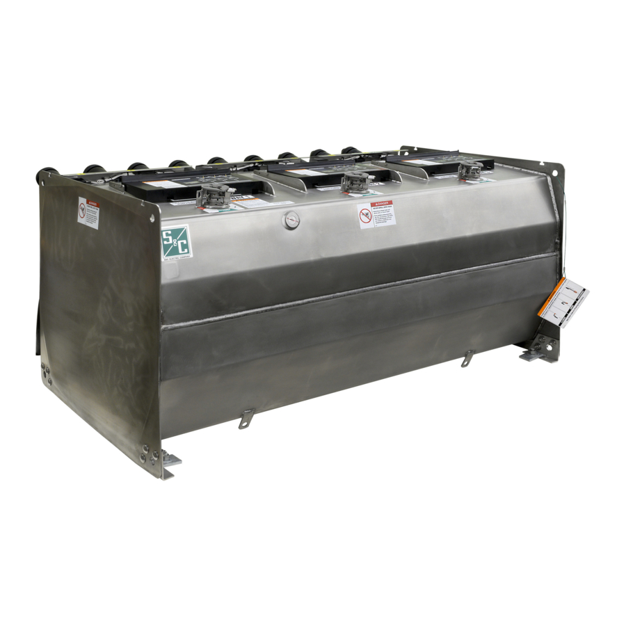
Source-transfer Vista Underground Distribution Switchgear features 600-ampere load-interrupter switches; microprocessor-controlled, resettable, vacuum fault interrupters; three-phase voltage sensing for each source; and self-power by means of voltage transformers. These elbow-connected components are enclosed in a submersible, gas-insulated, hermetically sealed welded-steel tank. See Figures 1 through 3, Figures 4 through 6, and Figure 7.
The three-position (Closed/Open/Grounded) load interrupter switches provide three-pole live switching of 600-ampere main feeders. They provide a visible gap when open and internal grounding for all three phases.
For fault-interrupter ways, microprocessor-controlled, resettable, vacuum fault interrupters in series with three position (Closed/Open/Grounded) disconnects provide either three-pole or single-pole switching and protection of 600-ampere main feeders or 200-ampere taps, laterals, or subloops. Fault interruption is initiated by a programmable overcurrent control. See S&C Instruction Sheet 681-530 for instructions on programming the control.
Three-phase voltage sensing is standard for each source. Three-phase current sensing is also provided when the Overcurrent Lockout option is specified.
A motor operator is provided for each of the two source ways in common-bus switchgear. Three motor operators—one for each source way and one for the tie-switch way—are provided for split-bus switchgear. The motor operator controls are located in the low-voltage enclosure or compartment. Each motor operator is provided with a control board that includes OPEN, CLOSE, and GROUND push buttons; switch-position indicating lamps; an operation counter; a PUSH TO TEST LAMPS push button; and a receptacle for a portable remote control.
The Micro-AT Source-Transfer Control is located in the low-voltage enclosure or compartment. The Micro-AT control uses an advanced microprocessor to perform control operations, as directed by settings programmed into the device at the factory and in the field.
Such settings—consisting of the control's operating characteristics and voltage-, current-, and time-related operating parameters—are entered into the control by means of a keypad on the front panel. Refer to S&C Instruction Sheet 515-500 for information on programming the Micro-AT control.

Figure 2. Vault-mounted style gear low-voltage enclosure.

Figure 3. UnderCover™ Style gear low-voltage enclosure.

Figure 4. Motor operator.

Figure 5. Low-voltage enclosure.

Figure 6. Motor operator control rack.

Figure 7. Termination side and top of switchgear.
● The gas-fill port is field-accessible for SF 6 models. For Vista Green switchgear, the gas-fill port is designed to prevent field refilling.
Understanding the Gas-Pressure Gauge
Vista switchgear incorporates a temperature-compensated gas-pressure gauge inside the tank to provide indication of the insulating-gas pressure. The gas-pressure gauge includes four distinct color-coded zones. See Figure 8.

Green zone:
The Vista switchgear unit is OK to operate.
Green/Yellow zone:
The Vista switchgear unit may have lost some gas but is still OK to operate. For SF6 models: The unit should be evaluated to determine whether it needs to be refilled with SF6 gas via the field-accessible fill-port and repaired accordingly. Contact S&C for assistance.
 Vista Green switchgear models are hermetically sealed. The gas-fill port is not accessible in the field as standard. Contact S&C for assistance.
Red zone:
The insulating gas may be below the minimum operating pressure for the gear. Vista switchgear should not be operated if the needle is in the Red zone. Contact S&C for assistance.
Orange zone:
The Vista switchgear unit has been overfilled or has a defective pressure gauge. For Vista switchgear and fieldaccessible ports, an external gauge can be used instead to verify the gas pressure before operation of the device. Contact S&C for assistance.
Vista Green switchgear models are hermetically sealed. The gas-fill port is not accessible in the field as standard. Contact S&C for assistance.
Gauge Needle Fluctuations from Rapid Ambient Temperature Changes
When the Vista switchgear tank experiences rapid changes in ambient temperature, the gas-pressure gauge needle may temporarily move to indicate a higher gas pressure when the tank is rapidly cooled or a lower gas pressure when the tank is rapidly heated. This phenomenon may occur, for instance, with sudden, direct exposure to intense sunlight.
The gas-pressure gauge uses a small reference gas chamber filled with helium to compensate for ambient temperature and altitude without applying correction factors. The gauge indicates tank pressure by measuring the pressure differential between the gas in the tank and the gas in the gauge. When the tank experiences rapid ambient temperature changes, the smaller volume of gas inside the gauge can change temperature more quickly than the larger volume of gas in the tank, which can lead to temporary movement of the needle. When the temperature stabilizes, the needle will return to its previous position within 1-2 hours.
For SF 6 units, if a sudden drop or increase in pressure is seen on the gauge, S&C recommends checking with an external gauge or waiting for ambient temperature conditions to stabilize to confirm that the needle has returned to its nominal position.
Vista Green switchgear models are hermetically sealed. The gas-fill port is not accessible in the field as standard. Contact S&C for assistance.
Operation
Manually Opening, Closing, or Grounding a Way
Do not operate this switchgear if the gas-pressure gauge is in the red zone. Failure to follow this precaution can result in a flashover and equipment damage.
STEP 1. Make sure the insulating-gas pressure gauge is in the green zone (or the green and yellow striped zone) by lifting the viewing window cover under Way 1. See Figure 10.

Note: If the SF 6 -gas pressure gauge is in the Green-and-Yellow striped zone, the switch gear can be operated but the tank must be repaired (if necessary) and refilled with SF 6 gas as soon as possible.
Note: If the Vista Green switchgear gas is in the Green-and-Yellow striped zone, the switchgear can be operated but must be serviced. Contact S&C for assistance. See Figure 11

NOTICE
Make sure the Micro-AT control is in the Manual position before performing manual operations. If the Micro-AT control is in the Automatic position, manual operation will not be possible.
STEP 2. Open the viewing window cover and confirm the position of the load-interrupter switch or the three-pole fault interrupter by visually observing the position of the blades (see Figures 12 and 13).

Also, inspect the current-carrying components inside the tank for any signs of abnormalities, but specifically for proper disconnect blade alignment, proper contact finger position, and dislodged hardware.
DO NOT operate the energized load interrupter switch or fault interrupter when it has dislodged hardware, or obvious signs of arcing or blade misalignment. Failure to follow this precaution can result in an injury or equipment damage.
ALWAYS confirm the position of switches or fault interrupters by VISUALLY OBSERVING blade position. Failure to follow this precaution can result in an injury or equipment damage.

STEP 3. Remove the electrical-operation mechanical blocking key from the motor operator. Verify the operation selector is in the far right position. This allows operation between the Closed and Open positions and prevents inadvertent operation directly from the Closed position to/from the Grounded position. See Figure 14.

STEP 4. If the operation selector is blocking operation, remove the electrical-operation mechanical blocking key from the motor operator, and rotate the operation selector out of the way, as shown in Figure 15.

STEP 5. In the far left position, the operation selector allows operation between the Open and Grounded positions, see Figure 16. The operation selector in this position prevents inadvertent manual operation directly from the Grounded position to the Closed position.

STEP 6. Insert the manual operating handle into the notch of the motor operator operating disk, as shown in Figure 17.

STEP 7. Rotate the manual operating handle in the appropriate direction to open, close, or ground the load-interrupter switch or three-pole fault interrupter. Operation to the Open position is shown in Figure 18.

STEP 8. When operating from the Closed to Open position, the operating handle must be rotated all the way to the line, as shown on the label to recharge the mechanism. See Figure 19. For the three-pole fault interrupter, the operating handle cannot be removed until the mechanism is fully charged.

For single-phase fault interrupters: When the fault-interrupter is operated from the Closed position, it will move to the Open position before the TRIP indicator will appear.
To reset the TRIP indicator: Operate by going from the Open position back to the Closed position.
For three-phase fault interrupters: When the fault-interrupter is operated from the Closed position, it will move toward the Open position, and the TRIP indicator will immediately appear after the indicator leaves the Closed position.
To reset the TRIP indicator: Continue operating until the Open position is reached.
ALWAYS make sure the cables connected to the load-interrupter switch or fault interrupter are de-energized before grounding the switchgear. Failure to follow this precaution can result in a flashover, injury, and equipment damage.
STEP 9. If operation is to the Grounded position, rotate the operation selector to the far left and make sure the cables connected to the load interrupter switch or fault interrupter are de– energized. See Figure 20. Check for voltage using the optional voltage indicator (option suffix "-L1" or "-L2") as instructed under the "Checking for Voltage Using Optional Voltage Indication" section, or use an alternate method.

STEP 10. Open the viewing window cover again and confirm the position of the load-interrupter switch or the three-pole fault interrupter by visually observing the position of the blades. Use the manual operating handle to move the switch to the Grounded position. See Figure 21.

Note: Replace the electrical operation mechanical blocking key when finished operating the gear with the manual operating handle.
Locking Out Grounded Position
To prevent operation of a motor operator into the Grounded position, insert a padlock through the operation selector and the right-side hole of the locking collar. See Figure 22.

Locking In Closed, Open, or Grounded Position
To lock a motor operator into position, insert a padlock through the operating disk and the center hole in the locking collar. See Figures 23 through 25.

Electrically Opening, Closing, or Grounding a Way
The controls for the motor operators are located in the low-voltage compartment or enclosure. Each motor operator is con trolled by a separate control board that includes CLOSE, OPEN, and GROUND operation pushbuttons, switch-position indicating lamps, an operations counter, a PUSH TO TEST LAMPS button, and a receptacle for a portable remote control. See Figure 26.

STEP 1. On the Micro-AT Source-Transfer Control, turn the MANUAL/AUTOMATIC switch to the MANUAL position. See Figure 27.

Note: For instructions regarding field programming and operation of the Micro-AT Source-Transfer Control, refer to S&C Instruction Sheet 515-500.
STEP 2. Verify the position indicating lamp on the control board matches the position of its associated motor operator. See Figures 26 and 28.

STEP 3. Make sure the operating handle is removed from the operating disk of the motor operator. See Figure 29.

STEP 4. Make sure the electrical-operation mechanical blocking key is placed in the motor operator operating disk. See Figure 30.

STEP 5. If the operation selector is blocking operation, rotate the operation selector out of the way, as shown in Figure 31. The electrical-operation mechanical blocking key may need be removed to move the operation selector. See Figure 30. The operation selector prevents inadvertent operation of the motor operator. Replace the mechanical blocking key. See Figures 32 and 33.

STEP 6. Press the PUSH TO TEST LAMPS pushbutton on each motor operator control board to ensure all of the LEDs are working. See Figure 34.

STEP 7. The following operations may be performed using pushbuttons, as shown in Figures 35 through 37:

- Close to Open
- Open to Ground
- Ground to Open
- Open to Close
An electrical interface in the controls will not allow the motor operators to move to/from the Close position directly from/to the Grounded position.
ALWAYS make sure the cables connected to the load-interrupter switch or fault interrupter are de- energized before grounding the switchgear. Failure to follow this precaution can result in a flashover, injury, and equipment damage.
Motor Operator Decoupling
STEP 1. Loosen and remove the bolt from the stop ring located on the operating disk collar. See Figure 38.

STEP 2. Lift the motor operator over the operating shaft of the gear. See Figure 39.

STEP 3. For submersible applications do not remove the cable from the motor operator. See Figure 40.

STEP 4. Reposition the motor operator to one side of the operating shaft. See Figure 41.

STEP 5. Refasten the bolt to the stop ring located on the operating disk collar. See Figure 42.

Checking for Voltage Using Optional Voltage Indicator
Before using a VOLTAGE indicator, ALWAYS test for proper operation. If the VOLTAGE indicator is not operating properly, test for voltage using an alternate method. Failure to follow this precaution can result in an injury or equipment damage.
NOTICE
When cleaning the surface of the VOLTAGE indicator, make sure the TEST button is thoroughly cleaned of dirt and debris. If light is blocked from the photocell and the sun is bright enough to power the test circuit, the VOLTAGE indicator will be in the Test mode and may give a false indication that all three phases of the associated load-interrupter switch or fault interrupter are energized. The Test mode is indicated by a dot  in the TEST window.
STEP 1. Clean the surface of the VOLTAGE indicator of dirt and debris. See Figure 43.

STEP 2. Check the PHASE indicators to determine whether there is any voltage at the associated bushings. See Figure 44. A flashing lightning bolt  in the PHASE indicator means voltage is present at the bushing. See Figure 45. A blank means either:

- There is voltage at the bushing.
- The VOLTAGE indicator is malfunctioning.
If any of the PHASE indicators are blank, proceed to Step 3 in the Checking for Voltage Using Optional Voltage
Indicator section to test the VOLTAGE indicator for proper operation.
STEP 3. Test the VOLTAGE indicator for proper operation as follows:
- Shine a flashlight approximately 4 inches (102 mm) above the photocell, and simultaneously cover the TEST button with a gloved finger. See Figure 46. When the sun is shining brightly, it can be used to power the test circuit.

- If a dot
![]() appears in the TEST window and a flashing lightning bolt
appears in the TEST window and a flashing lightning bolt ![]() appears in each of the three PHASE indicators, then the VOLTAGE indicator is operating properly. See Figure 47.
appears in each of the three PHASE indicators, then the VOLTAGE indicator is operating properly. See Figure 47.

- If the dot
![]() or any of the flashing lightning bolts
or any of the flashing lightning bolts ![]() does not appear, make sure the TEST button is completely covered with a gloved finger so no light shines on the photocell, and there is adequate light (provided either by a flashlight or the sun) to power the test circuit. See Figure 48. If the dot
does not appear, make sure the TEST button is completely covered with a gloved finger so no light shines on the photocell, and there is adequate light (provided either by a flashlight or the sun) to power the test circuit. See Figure 48. If the dot ![]() or any of the flashing lightning bolts
or any of the flashing lightning bolts ![]() still do not appear, the VOLTAGE indicator may be damaged. Test for voltage using an alternate method. See Figure 49.
still do not appear, the VOLTAGE indicator may be damaged. Test for voltage using an alternate method. See Figure 49.


Low-Voltage Phasing Using Optional Voltage Indicator with Phasing
STEP 1. Clean the surface and phasing pins of the VOLTAGE indicator of dirt and debris. See Figure 50.

Test the voltage indicators for proper operation by following the "Checking for Voltage Using Optional Voltage Indication" section. If a VOLTAGE indicator is not operating properly, phasing should be per formed using an alternate method.
STEP 2. Use a high-impedance voltmeter, as shown in Figure 51, to verify voltage is present and to determine the phase-to-ground voltage for each phase of the two ways ● to be phased as follows:

- Set the voltmeter for volts ac.
- Connect one of the test probes of the voltmeter to the metal tank of the switchgear to ground the voltmeter. See Figure 52.

- Place the other test probe on each of the phasing pins, in turn, for the two ways to be phased and to measure the phase-to-ground voltage. See Figure 52.
- If the voltage measured at each phasing pin is greater than zero and they are equal, proceed to Step 3 in the Low-Voltage Phasing Using Optional Voltage Indicator with Phasing section.
- If the voltage measured at any of the phasing pins is zero, the phases are not energized and phasing cannot be per formed. If the voltages measured are not equal, the voltmeter may not be operating properly. Phasing Should Be Performed Using an Alternate Method.

● A "way" consists of a three-phase load-interrupter switch, three-phase fault interrupter, bus tap, or three single-phase fault interrupters.
STEP 3. Determine the phase-to-phase relationships of the two ways to be phased as follows:
- Remove the test probe of the voltmeter from the switchgear tank. Place one of the test probes on PHASING PIN 1 of the first way and place the other probe on PHASING PIN 1 of the second way. Measure the phase-to-phase volt age. See Figure 53. When comparing the same phase of the two ways, the voltage should be zero or close to zero, indicating the cables are in phase.

Keep the test probe on PHASING PIN 1 of the second way and move the other test probe to PHASING PIN 2 of the first way. Measure the phase-to-phase voltage. See Figure 54. When comparing different phases of the two ways, the voltage should be 1.7 to 2 times the phase-to-ground voltage measured in Step 2.

Keep the test probe on PHASING PIN 1 of the second way and move the other test probe to PHASING PIN 3 of the first way. Measure the phase-to-phase voltage. See Figure 55. Again, when comparing different phases of the two ways, the voltage should be 1.7 to 2 times the phase-to-ground voltage measured in Step 2.

- Repeat Steps 3(b) through 3(d) for PHASING PIN 2 and PHASING PIN 3 of the second way.
- If all of the phase-to-phase relationships are correct, the cables are in phase and are properly installed.


Maintenance
Components
No maintenance is required for source-transfer Vista Under ground Distribution Switchgear. However, occasional inspection of the switchgear and exercising of the load-interrupter switches and fault interrupters are recommended. Two battery chargers are available for Vista Underground Distribution Switchgear. For information on battery charger TA-3409 and instructions for replacing the battery, see S&C Instruction Sheet 680-540. For information on battery charger TA-2646, identifiable by number G-4875 on the front panel, see S&C Data Bulletin 682-97.
When access to the bushings or high-voltage components is required for inspection, service, or repairs, always observe the pre cautions below. Failure to observe these precautions will result in serious personal injury or death.
- Access to switchgear must be restricted only to qualified per sons. See the "Qualified Persons" section,
- Always follow safe operating procedures and rules
- Before touching any bushings or components, always disconnect load-interrupter switches and fault interrupters from all power sources (including backfeed) and test for voltage
- After the switchgear has been completely disconnected from all sources of power and tested for voltage, ground all load-interrupter switches and fault interrupters
- Always assume the bushings are energized unless proved otherwise by test, by visual evidence of an open-circuit condition at the load-interrupter switch or fault interrupter, or by observing that the load interrupter switch or fault interrupter is grounded
- Test the bushings for voltage using the Voltage- Indication feature (if furnished) or other proper high-voltage test equipment
- Make sure the switchgear tank and pad-mounted enclosure (if furnished) are properly grounded to the station or facility ground. Do not return equipment to service unless such grounds are properly made.
★ These recommendations may differ from company operating procedures and rules. Where a discrepancy exists, users should follow their company's operating procedures and rules.
Returning Equipment to Service
When returning the equipment to service, the following procedures should be observed:
STEP 1. Make sure the load-interrupter switch and fault interrupter grounding means are removed.
STEP 2. Make certain the load-interrupter switches and fault interrupters are in the correct Open or Closed positions.
STEP 3. If a pad-mounted enclosure is furnished, close and padlock the termination compartment before energizing the circuit and operating any switching devices.
STEP 4. Padlock the switchgear a nd low-voltage compartment or enclosure before leaving the site even momentarily. See Figure 56. Observe this procedure even in those cases where the gear is accessible only to qualified persons.

Enclosure Finish
The responsibility for ensuring the finish protects the enclosure lies with both the manufacturer and the user. Enclosures provided are finished with the Ultradur ® II Outdoor Finish, which provides lasting protection. To retain this protection, the user should take periodic corrective action as follows:
STEP 1. Touch-up any penetration of the finish to bare metal—such as scratches and abrasions caused by shipping or vandalism—to maintain the original integrity. S&C touch-up finish and primer are available in aerosol spray cans. See Figure 57. No other finish or primer is approved. The area to be touched up should be cleaned to remove all oil and grease. Sand the area, removing any traces of rust that may be present, and make sure all edges are feathered before applying primer.

STEP 2. Provide an occasional simple wash-down —such as an automobile would be given—to remove surface contaminants. Use any ordinary mild household detergent solution.
STEP 3. In those cases where the enclosure must be refinished by the user before the finish has weathered—for example, to match other equipment—a special precaution must be taken. The entire surface must be sanded to provide a tooth to bond the new coat to the Ultradur II Outdoor Finish.
Maintenance Recommendations in Extremely Corrosive Environments
For applications involving exposure to extremely corrosive environmental conditions (i.e. industrial chemicals, CaCl2, etc.) that may affect the condition of the switchgear tank, S&C's recommended periodic cleaning could provide extended life. Contact S&C if corrosion on the tank is found.
For outer pad-mount or custom-designed enclosures that have already experienced some corrosion, follow the instructions in the "Enclosure Finish" section for specific instructions. If no further exposure to a corrosive environment is expected, one treatment may be enough.
Dielectric Testing
Routine Switchgear Testing
For the convenience of users who normally perform electrical tests on system components such as switchgear, appropriate with stand test values for Vista switchgear are given in the Table 1. These test values are significantly greater than the normal operating volt age of the switchgear and are near the flashover voltage of the gear. They should be applied only when the switchgear is completely de-energized and disconnected from all power sources.
On Vista switchgear equipped with internal voltage transformers, do not apply test voltage greater than normal system voltage to the B phase unless both incoming load-interrupting switches are in the Open position. Refer to Figure 58, that shows the location of the B phase. Failure to follow this precaution can result in an injury or equipment damage.

When performing electrical withstand tests on Vista switchgear, always observe the following precautions. Failure to observe these precautions can result in a flashover, injury, and equipment damage
- Completely de-energize the switchgear and disconnect it from all power sources
- Terminate bushings with an insulated cap or other appropriate cable termination capable of withstanding the test voltage
- Verify the insulating-gas pressure gauge is in the green zone.
| Vista Switchgear Rating, kV | Withstand Test Voltage, kV | |||
| 50 Hertz | 60 Hertz | Impulse (BIL) | Power Frequency ① | Dc ②③ |
| 12 | 15.5 | 95 | 27 | 42 |
| 24 | 27 | 125 | 40 | 62 |
| 36 | 38 | 150 | 50 | 82 |
① The listed power-frequency withstand test voltages are approximately 80% of the design values for new equipment.
② The listed dc withstand test voltages are approximately 80% of the design values for new equipment.
③ Dc withstand test voltages are given for reference only for those users performing dc withstand tests. The presence of these values does not imply a dc withstand rating or performance requirements for the switch gear. A dc withstand design test is specified for new equipment because the switchgear may be subjected to dc test voltage when connected to the cable. The dc withstand test values listed in the table are approximately equal to the ac peak test voltage.
Cable Testing and Fault Locating
Dc testing of installed cables is performed to determine the condition of the cables and to locate faults. Industry standards, such as IEEE 400, "IEEE Guide for Making High-Direct-Voltage Tests on Power Cable Systems in the Field," describe such testing and should be referenced for selection of the test procedures. Dc testing also includes cable "thumping," i.e., the sudden application of dc voltage from a large capacitor for the purposes of fault locating, which causes transients and voltage doubling at the end of the open cable. When the cables are attached to the switchgear, the gear will also be subjected to the dc test voltages.
NOTICE
On Vista switchgear equipped with internal voltage transform ers, do not apply test voltage greater than normal system voltage to the B phase of the incoming source ways. Refer to Figure 59 that shows location of the B phase. If this instruction is not fol lowed, damage to the voltage transformers will result.

The dc withstand capability of the switchgear may be reduced because of aging, damage, gas leakage, or electrical or mechanical wear. Therefore, the dc test voltage must be selected so it does not exceed the withstand limits of the switchgear. Application of dc test voltages greater than the withstand capability of the switchgear can result in a flashover, injury, and equipment damage. In addition, always verify the SF 6 pressure gauge is in the green zone before proceeding with any testing.
Do not exceed the test voltages given in Table 1 and Table 2. Exceeding the test voltages can cause a flashover of the isolating gap or phase-to-phase insulation of the switchgear. This can lead to a power-frequency fault in the gear or of the dc test source and result in severe personal injury or death.
Vista switchgear has been designed to allow dc testing of the cables with the otherpa ways of the gear energized. The integral grounding switch may be used to ground the cable. After testing, the dc test equipment should be used to discharge any stored charge on the cable before regrounding with the grounding switch. The dc test voltages and dc cable thumping voltages should not exceed the voltages given in Table 2.
Table 2. Maximum Cable Test and Cable Thumping Voltages
| Vista Switchgear Rating, kV | Dc Cable Test Voltage, | Dc Cable Thumping | ||
| 50 Hertz | 60 Hertz | Impulse (BIL) | kV | Voltage, kV ① |
| 12 | 15.5 | 95 | 30 | 15 |
| 24 | 27 | 125 | 40 | 20 |
| 36 | 38 | 150 | 40 | 20 |
When it is necessary to test the cables connected to a unit of energized switchgear, proper isolation of the power-frequency source from the dc test source must be maintained. Follow the recommendations by the manufacturer of the dc test equipment or fault-locating equipment. The user's operating and safety procedures should be followed for grounding the cable, connecting the dc test source, isolating the dc test source (in case of flashover), ungrounding the cable, applying the dc test source, discharging the cable, and regrounding the cable. Failure to follow these operating and safety procedures may result in injury or equipment damage.
Fault-Interrupter Testing
When performing dielectric tests on Vista switchgear, the vacuum fault interrupters will not be subject to voltage across the open gap because the disconnect switch will isolate the vacuum interrupter from the test voltage. Because the vacuum interrupter will not be energized across the open gap, there is no expo sure to X-rays normally associated with high-voltage testing of vacuum devices. Routine testing of the vacuum fault interrupt ers is not recommended. For those users who desire to test the vacuum interrupters, contact the nearest S&C Sales Office for specific instructions.
Resistance Measurement
De-energize the Vista Underground Distribution Switchgear before per forming the resistance measurements described in this procedure. Follow all applicable safety procedures. Failure to de-energize the Vista Underground Distribution Switchgear before taking resistance measurements can result in serious injury or death.
Resistance measurements are used to look for areas of the gear that may exhibit poor contact between currentcarrying parts. Resistance measurements are taken using a fourterminal measuring dev ice that prov ides at least 100 amperes of current to the main circuit.
Resistance measurements should be taken from the bushing conductor across each way to the same phase on each way of the unit. For example, a measurement would be taken from Way 1 Phase A to Way 2 Phase A, from Way 2 Phase A to Way 3 Phase A, from Way 1 Phase A to Way 3 Phase A, from Way 1 Phase B to Way 2 Phase B, etc.
To measure resistance, perform the following procedure:
STEP 1. Clamp the two current-carrying probes of the resistance-measuring device to the bushing conductors of the current-carrying path to be measured. See Figure 60. In this example, the resistance is being taken between Way 1 Phase A and Way 2 Phase A.

● Adhere to your company's standards in regards to using hand PPE when taking resistance measurements.
NOTICE
DO NOT take resistance measurements from the threaded area of the bushing stud. Resistance measurements taken through the threads of the bushing stud will be inaccurate. See Figure 61
STEP 2. Clamp or touch the voltage-carrying probes of the resistance-measuring device to the flat conductive surface of the bushings that make up the current-carrying path. Make sure the measurement probe is in contact with the current-carrying flat face of the bushing conductor rod. If using clamp-style probes, slide the clamp all the way up against the current-carrying face to get a good connection. See Figure 61.

STEP 3. Record the resistance measurement. Acceptable resistance values are:
- Less than 500 microohms
- Less than 600 microohms for tie switches
● Adhere to your company's standards in regards to using hand PPE when taking resistance measurements.
Documents / Resources
References
Download manual
Here you can download full pdf version of manual, it may contain additional safety instructions, warranty information, FCC rules, etc.
Advertisement


Need help?
Do you have a question about the Vista and is the answer not in the manual?
Questions and answers