S&C TripSaver II Manual
Cutout-mounted recloser
Hide thumbs
Also See for TripSaver II:
- Manual (107 pages) ,
- Installation, operation, and configuration (89 pages) ,
- Installation and operation manual (36 pages)
Table of Contents
Advertisement
Quick Links
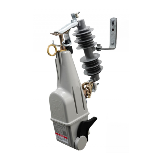
TripSaver
II Cutout-Mounted Recloser
®
Outdoor Distribution (15 kV and 25 kV)
Table of Contents
. . . . . . . . . . . . . . . . . . . . . . . . . . . . . . . .
Qualified Persons . . . . . . . . . . . . . . . . . . . . . . . . . . . 3
Read this Instruction Sheet . . . . . . . . . . . . . . . . . . . 3
Retain this Instruction Sheet . . . . . . . . . . . . . . . . . . . 3
Proper Application . . . . . . . . . . . . . . . . . . . . . . . . . . 3
Warranty . . . . . . . . . . . . . . . . . . . . . . . . . . . . . . . . . . 4
End User License Agreement . . . . . . . . . . . . . . . . . . 4
. . . . . . . . . . . . . . . . . . . . . . . . . .
Understanding Safety-Alert Messages . . . . . . . . . . . 5
Following Safety Instructions . . . . . . . . . . . . . . . . . . 5
Replacement Instructions and Labels . . . . . . . . . . . 5
. . . . . . . . . . . . . . . . . . . . . . . . .
Packing . . . . . . . . . . . . . . . . . . . . . . . . . . . . . . . . . . . 7
Inspection . . . . . . . . . . . . . . . . . . . . . . . . . . . . . . . . . 8
Handling . . . . . . . . . . . . . . . . . . . . . . . . . . . . . . . . . . 8
®
Computer Requirements . . . . . . . . . . . . . . . . . . . . . 9
Downloading Software . . . . . . . . . . . . . . . . . . . . . . . 9
Software Installation . . . . . . . . . . . . . . . . . . . . . . . . .10
. . . . . . . . . . . . . . . . . . . . . . . . . . . . . . . . . . . .
Obtaining the Transceiver ID . . . . . . . . . . . . . . . . . .16
October 10, 2022
© S&C Electric Company 2014-2022, all rights reserved
Protection Setup Using
Service Center Configuration Kit
. . . . . . . . . . . . . . . . . . . . . .
. . . . . . . . . .
For Overhead Distribution Systems
3
Launching the Software . . . . . . . . . . . . . . . . . . . . . .18
Terminology . . . . . . . . . . . . . . . . . . . . . . . . . . . . . . .18
Overview . . . . . . . . . . . . . . . . . . . . . . . . . . . . . . . . . .19
Menu Bar Functions . . . . . . . . . . . . . . . . . . . . . . . . 24
5
. . . . . . . . . . . . . . . . . . . . . . . . . . . . . . . . .
Open Snapshot . . . . . . . . . . . . . . . . . . . . . . . . . . . . 25
Close Snapshot . . . . . . . . . . . . . . . . . . . . . . . . . . . 26
Save Snapshot . . . . . . . . . . . . . . . . . . . . . . . . . . . . 27
Load Setpoints . . . . . . . . . . . . . . . . . . . . . . . . . . . . 28
6
Save Setpoints . . . . . . . . . . . . . . . . . . . . . . . . . . . . 29
7
Exit . . . . . . . . . . . . . . . . . . . . . . . . . . . . . . . . . . . . . 29
Connect to Device . . . . . . . . . . . . . . . . . . . . . . . . . 30
Disconnect . . . . . . . . . . . . . . . . . . . . . . . . . . . . . . . 32
. . . . . . . . . . . . . . . . . . . . . . . . . . . . . . . .
9
Validate . . . . . . . . . . . . . . . . . . . . . . . . . . . . . . . . . . 33
Apply . . . . . . . . . . . . . . . . . . . . . . . . . . . . . . . . . . . . 35
Revert . . . . . . . . . . . . . . . . . . . . . . . . . . . . . . . . . . . 36
. . . . . . . . . . . . . . . . . . . . . . . . . . . . . . . .
Options . . . . . . . . . . . . . . . . . . . . . . . . . . . . . . . . . . 37
14
Create Report . . . . . . . . . . . . . . . . . . . . . . . . . . . . . 38
Firmware Update . . . . . . . . . . . . . . . . . . . . . . . . . . 39
USB Transceiver Firmware Update . . . . . . . . . . . . 43
Restore Profile . . . . . . . . . . . . . . . . . . . . . . . . . . . . 46
TABLE OF CONTENTS CONTINUED ▶
®
. . . . . . . . .
. . . . . . . . . . . . . . . . . . . . . . . . . .
Instruction Sheet 461-504
18
25
30
33
37
Advertisement
Table of Contents

Subscribe to Our Youtube Channel
Related Manuals for S&C TripSaver II


Summary of Contents for S&C TripSaver II
-
Page 1: Table Of Contents
TripSaver II Recloser . . . . . . . . . . . . . . . . . . . - Page 2 Communication Settings Screen . . . . . . . . . . . . . .101 TripSaver II Recloser is in R-NR Mode . . . . . . .130 R–NR Functions Screen .
-
Page 3: Introduction
Safety Precautions on pages 5 and 6 . The latest version of this publication is available online in PDF format at sandc.com/en/support/product-literature/ . Retain this This instruction sheet is a permanent part of the TripSaver II Cutout-Mounted Recloser. Designate a location where users can easily retrieve and refer to this publication. Instruction Sheet... -
Page 4: Warranty
The end user is granted a nontransferable, non-sublicensable, nonexclusive license to use the TripSaver II Service Center Configuration Software and/or other software furnished with License TripSaver II Cutout-Mounted Reclosers only upon acceptance of all the terms and conditions Agreement of the seller’s end user license agreement set forth in Price Sheet 155. -
Page 5: Safety Information
Several types of safety-alert messages may appear throughout this instruction sheet and on Safety-Alert labels attached to the TripSaver II Cutout-Mounted Recloser or in the TripSaver II Service Center Configuration Software. Become familiar with these types of messages and the importance of... -
Page 6: Safety Precautions
“corded” power module (power module with ac adapter and extension cord) to the base of the TripSaver II recloser . The corded power module is ONLY intended to be used for setup and data collection when the TripSaver II recloser is de-energized and removed from the utility pole . -
Page 7: Shipping And Handling
Shipping and Handling Shipping and Handling Packing A complete TripSaver II Configuration Kit, which weighs about 4 lbs. (1.8 kg) and works with both 15-kV and 25-kV TripSaver II reclosers, consists of the following items stored in a carrying case:... -
Page 8: Inspection
. Only remove components from the carrying case when they are ready to be used . After a TripSaver II recloser has been configured, always return components to the carrying case for protection . -
Page 9: Installing Tripsaver Ii Service Center Configuration Software Version
• Administrative privileges for software installation. Downloading Software TripSaver II Service Center Configuration Software (SCC) Version 2.0 is available for download only to customers who have purchased the configuration kit. The latest release is posted on the S&C Automation Customer Support Portal at sandc.com/en/support/SC- customer-portal/. -
Page 10: Software Installation
See Figure 4 on page 11. NOTICE If TripSaver II Service Center Configuration Software version 1 .8 or 1 .9 was previously installed on the computer, the installation process will remove it and install software version 2 .0 . - Page 11 Installing TripSaver II Service Center Configuration Software Version 2.0 ® Figure 4. The SCC v2.0 Installation Setup Wizard. Click on the Next button to continue, or click on the Cancel button to quit the STEP 3. installation process. STEP 4. The next dialog box to open allows the installer to select the installation folder.
- Page 12 Installing TripSaver II Service Center Configuration Software Version 2.0 ® STEP 5. When the installation folder has been selected, the Ready to Install dialog box opens. See Figure 6. Click on the Install button to begin the installation. Click on the Back button to review or change the settings, or click on the Cancel button to quit the installation process.
- Page 13 II Service Center Configuration Software Version 2.0 ® STEP 6. When the TripSaver II Service Center Configuration Software Version 2.0 has been installed successfully, the Installation Successfully Completed dialog box opens. See Figure 8. Click on the Close button to exit the installer.
-
Page 14: Installing The Usb Transceiver And Power Supply
Installing the USB Transceiver and Power Supply Assembling and A USB transceiver must be installed on the computer to communicate with a TripSaver II recloser. Note: Installing the configuration software and running the software in an Installing the USB offline mode does not require the presence of a USB transceiver. Transceiver Screw the threaded bottom of the antenna into the threaded connector on the STEP 1. -
Page 15: Assembling The Power Supply And Powering The Tripsaver Ii Recloser
Installing the USB Transceiver and Power Supply Assembling the Power A TripSaver II recloser can be powered by the power module to enable its communica- tion capability. Complete the following steps before attempting to communicate with a Supply and Powering TripSaver II recloser. -
Page 16: Obtaining The Transceiver Id
• Method 1: The Transceiver ID is embedded in the QR code laser-etched onto the lower housing of each TripSaver II recloser. See Figure 16 on page 17. Download a free QR scanner app to a smart phone and scan the QR code to obtain the Transceiver ID. - Page 17 Installing the USB Transceiver and Power Supply • Method 3: The Transceiver ID is also printed on the back of the yellow “DO NOT DROP—HANDLE WITH CARE” tag attached to each TripSaver II recloser when it leaves S&C Electric Company. See Figure 18.
-
Page 18: Using Tripsaver
II Service Center Configuration Software Version 2.0 ® Launching the Click on the SCC 2.0 icon on the desktop or in the Start menu to launch TripSaver II Service Center Configuration Software Version 2.0. See Figure 9 on page 13. Software... -
Page 19: Overview
II Service Center Configuration Software Version 2.0 ® Overview TripSaver II Service Center Configuration Software is used to communicate with and configure TripSaver II Cutout-Mounted Reclosers. The user interface is organized in the following way: Menu Bar and Quick Access Toolbar At the top of the user interface is a menu bar that has a number of commands. - Page 20 Using TripSaver II Service Center Configuration Software Version 2.0 ® Menu Tree On the left side of the user interface is a menu tree that contains the names of available screens. Click on the menu tree items to navigate through screens. Active screens are highlighted, and the rest remain gray.
- Page 21 Using TripSaver II Service Center Configuration Software Version 2.0 ® Additional Information Bar At the bottom of the screen is an information bar that contains additional recloser-related information. See Figure 23. Figure 23. The information bar at the bottom of the screen. S&C Instruction Sheet 461-504...
- Page 22 3) Sectionalizing Settings, 4) LCD Screen Settings, 5) Communications Settings, and 6) Local Manual Open. See Figure 24. Note: Validation in Standalone mode will validate for a TripSaver II recloser rated 100 amperes continuous. Validation in Connected mode will validate set t i ng s ba sed on t he a ct ua l cont i nuou s cu r rent set t i ng of t he recloser: 40 A, 100 A, or 200 A.
- Page 23 “Restoring Profile If Lost During a Firmware Update” section on page 118 . Under Con nected mode, users ca n v iew existing settings, status infor- mation, and event logs of the TripSaver II recloser, apply new settings to the control, download a snapshot file, or perform functional tests. Three addi- tional screens are available under this mode.
-
Page 24: Menu Bar Functions
Using TripSaver II Service Center Configuration Software Version 2.0 ® Menu Bar Functions At the top of the user interface is a menu bar that contains a number of commands that are described in this section. Below the menu bar is a quick access toolbar that contains the most frequently used commands found in the menu bar. -
Page 25: File Menu
File Menu Open Snapshot When a snapshot is saved, the configuration software can open it later and the data can be viewed offline. A snapshot file can be opened under the Standalone (offline) or Connected (online) mode or when another snapshot is already open. Users can also edit the settings part of a snapshot file and then save the modified settings to a setpoints file. -
Page 26: Close Snapshot
TripSaver II recloser. If no setpoint changes have been saved in the edit buffer, a prompt will open asking the user to do so. The TripSaver II recloser can be reconnected after a snapshot file is opened. See the “Connect to Device” section on page 30. -
Page 27: Save Snapshot
File Menu Save Snapshot This feature is only available when connected to and communicating with a TripSaver II recloser. To save a snapshot, select the File>Save Snapshot option from the Main menu or click on the Save Snapshot icon in the quick access toolbar. A File Selection dialog box will open, allowing selection of a name and location where the file is to be saved. -
Page 28: Load Setpoints
TripSaver II recloser using version 1.9 (or later) firmware, the older setpoints file will configure the TripSaver II recloser with the 1.8 (or earlier) settings by default. If any of the new functions available in SCC Software version 2.0 are required, they must be manually set after the older setpoints file is loaded. -
Page 29: Save Setpoints
Setpoint files have the .xspt extension. When connected to a TripSaver II recloser or when a Snapshot file is open, the setpoint files saved only contain setting fields avail- able to the firmware version of the TripSaver II recloser or snapshot file from which the setpoint files have been generated. -
Page 30: Connection Menu
Next, a Transceiver ID Request dialog box will open. Enter the Transceiver ID of the TripSaver II recloser to be connected, and click on the OK button to connect. If the TripSaver II recloser is furnished with firmware version 1.8 or later, the Auto Detect button can be used to auto-detect the Transceiver ID. - Page 31 Transceiver version 1.6 or 2.0 and SCC Software version 2.0 will be backward-compatible with all TripSaver II recloser firmware versions : 2.0, 1.9, 1.8, 1.7, 1.6, 1.5, 1.3, and 1.0. To connect successfully with TripSaver II reclosers with firmware version 2.0, a USB transceiver with firmware version 2.0 is required.
-
Page 32: Disconnect
Connection Menu The connection may not succeed if the TripSaver II recloser is not powered up or the 32-bit transceiver ID is incorrect. If the connection is not successful, the message shown in Figure 43 will open. Click on the Retry button to restart the connection process, or click on the Cancel button to quit the process. -
Page 33: Data Menu
TripSaver II recloser (40 A, 100 A, or 200 A) and validate settings accordingly. If a setpoint value entered is out of range, the border of that edit field will be... - Page 34 Data Menu Figure 46. The border of the erroneous field, highlighted in red. highlighted in red automatically. Any invalid value will be erased from the edit field when navigating to another settings screen. For validation under the Connected (online) mode, various error messages are also generated if mandatory setpoint fields are not filled in.
-
Page 35: Apply
The Apply function is only available when connected to and communicating with a TripSaver II recloser. To apply newly configured settings to the TripSaver II recloser, select the Data>Apply option from the Main menu or click on the Apply button in the quick access toolbar. -
Page 36: Revert
• For Connected (online) mode—Active settings presently residing in the connected TripSaver II recloser • When a snapshot file is open—Settings saved in the snapshot file Note 1: Loading a setpoint file does not create a new original state. -
Page 37: Tools Menu
Tools Menu Options Under the Options feature, preferences can be changed for PC-to-TripSaver II commu- nication-related logging, several communication parameters can be set, and the default settings the software uses under the Standalone (offline) mode can be changed. The two logging-related features are mainly intended for engineering-debugging use in case the communications encounter any unexpected errors. -
Page 38: Create Report
Intersend Delay, ms. Specify the duration (in milliseconds) the software waits before it sends the next communication request to a TripSaver II recloser. The default is 20. Note: These settings are optimally set and should only be changed when directed by an S&C technician. -
Page 39: Firmware Update
TripSaver II Service Center Configuration Software 2.0 (this release) is backward- compatible with all TripSaver II recloser firmware versions: 2.0, 1.9, 1.8, 1.7, 1.6, 1.5, 1.3, and 1.0. It can update TripSaver II recloser firmware versions 1.5, 1.6, 1.7, and 1.8 to 1.9, and firmware version 1.0 to 1.3. - Page 40 Tools Menu STEP 2. Make a note of the serial number, starting with “TCMR,” of the TripSaver II recloser to be updated. See Figure 52. This number is also etched on the body of the TripSaver II recloser. Figure 52. The TripSaver II recloser serial number and Signal Strength indicator locations.
- Page 41 • Updates the firmware (See Figure 56 on page 42.) • Applies the settings and historical logs from the saved snapshot file back to the TripSaver II recloser (If new features are available after the update, default settings for those features will be loaded to the TripSaver II recloser.) •...
- Page 42 Tools Menu Figure 56. The firmware update progress bar. STEP 7. A “Success” message will appear upon successful completion of the firmware update. After the update, check the Status screen to make sure the latest firmware has been applied correctly. See Figure 57. Figure 57.
-
Page 43: Usb Transceiver Firmware Update
To upgrade the USB transceiver firmware, complete the following steps: STEP 1. Plug a USB transceiver with firmware version 1.6 into the USB port of the computer. Do not connect to a TripSaver II recloser. Keep the Service Center Configuration Software in Standalone mode. NOTICE DO NOT unplug the USB transceiver until the USB Transceiver Firmware Update process is completed . - Page 44 Tools Menu Figure 60. The USB transceiver firmware update progress bar. When the update is complete, a dialog box will appear displaying a success STEP 4. message. Click on the OK button. See Figure 61. Figure 61. The USB transceiver firmware update success message. S&C Instruction Sheet 461-504...
- Page 45 Note: If the USB transceiver is up to date, the dialog box in Figure 62 will appear. Note: If the service center configuration software is in Connected mode (communi- cating with a TripSaver II recloser) the dialog box shown in Figure 63 will appear. The USB Transceiver Firmware Update procedure can only be completed in Stand- alone (offline) mode.
-
Page 46: Restore Profile
Tools Menu Restore Profile Information on the Restore Profile menu item can be found in “Restoring the Profile If Lost During a Firmware Update” section on page 118. Clear “Service Now” The Clear “Service Now” menu item will only appear when a Clear Service Now pro- cedure is being performed. -
Page 47: Help Menu
Software Selecting the Help>About S&C TripSaver II Service Center Configuration Software About S&C TripSaver II option displays the copyright information and revision information of the TripSaver II Service Center Service Center Configuration Software, its database, and firmware included. Configuration Software To magnify the main body of the screen, click on the Zoom In button. - Page 48 Help Menu Figure 66. Reducing the screen size. S&C Instruction Sheet 461-504...
-
Page 49: Additional Information Bar
(online) mode. It indicates the serial number of the TripSaver II recloser presently connected. “Snapshot From” is displayed when a snapshot file is open. It indicates the serial number of the TripSaver II recloser from which the snapshot being viewed was saved. See Figure 68. Figure 68. The “Snapshot From” serial number. - Page 50 Additional Information Bar Transceiver ID. This indicates the transceiver ID of the TripSaver II recloser presently connected. It is only available for the Connected (online) mode. Battery State of Charge. This indicates the state of charge of the rechargeable battery inside a TripSaver II recloser furnished with the Extended Open Interval feature (“-O”...
-
Page 51: Entering Data
Setpoints and Setpoint Setpoints are user-changeable settings entered into the control to configure a TripSaver II recloser. Setpoints are displayed as check boxes, data-entry fields, and Files selection menus. The font color of all setpoints is light blue. Complete a setpoint con- figuration by clicking anywhere outside its editable field. - Page 52 Entering Data Color Change of Setpoints Border The color of the border of a setpoint field changes according to the following rules: At any time if a setpoint field holds a value within the valid range but is different from the “original”...
-
Page 53: Working With A Snapshot File
.xdss. Saving a snapshot is available only in the Connected (online) mode. The snapshot saved always has the same version number as the firmware version of the TripSaver II recloser where the snapshot file was generated. A snapshot file can be opened in the Standalone (offline), the Connected (online) mode, or when another snapshot is already open. -
Page 54: Informational And Settings Screens
The Initial Trip operation is required; if that is the only trip operation selected, the TripSaver II recloser will operate one time and then drop open (i.e., single shot to lockout). One of the available TCC curves listed in Appendix A on page 123 must be selected for the initial trip and for each of the additional tests to be added. - Page 55 TripSaver II Cutout-Mounted Recloser and the downstream recloser when each is set with fast and slow TCC curves. If the downstream recloser operates, the upstream TripSaver II recloser will shift (without operating) from its Initial Trip curve setting to a user-configured (usually slower) Sequence Coordination time-current char- acteristic curve.
- Page 56 Informational and Settings Screens Add a Test Operation. Click on the green Add a Test button at the bottom of screen to add a new Test operation to the end of the test sequence. See Figure 78. Test operations can only be added sequentially from the top down. Figure 78.
- Page 57 Informational and Settings Screens Open Interval and O/C Sequence Time If the reclosing sequence consists of just the Initial Trip operation (i.e., single shot to lockout), the reset time does not need to be entered. If there are two or more trip opera- tions, the open interval must be entered between adjacent trip operations in addition to the reset time.
- Page 58 TCC curve will reset to its setting defined in the Trip operation. Note: An active O/C Sequence Time timer will not expire after a TripSaver II recloser loses power. It will continue counting down until the defined duration has been reached.
- Page 59 All existing settings will be erased. See Figure 82. Note: Any unwanted curve must be removed before applying new settings to a TripSaver II recloser. Leaving a curve added with completely blank settings will not allow the settings to be applied.
- Page 60 Informational and Settings Screens Configuring a Trip Operation When a test is added, a new configuration area for that Test operation will be displayed, but with only two user-configurable fields available at the beginning—the Emulated Device drop-down menu and the Open Interval setting between the newly added Trip operation and the previous Trip operation.
- Page 61 400 A, the software will prompt with an overload warning of 40 A for TripSaver II reclosers rated 40 A continuous, 100 A for TripSaver II reclosers rated 100 A continuous, and 200 A for TripSaver II reclosers rated 200 A continuous.
- Page 62 “D/T” (Definite Time) or “E/M” (Electromechanical). (This is not to be confused with O/C Sequence Time setting. “Reset” here means how fast that curve will reset if it has picked up but the fault disappears before the TripSaver II recloser could trip.) This field is mandatory.
- Page 63 Informational and Settings Screens Time Adder (check box). Select this check box to enable the Time Adder setting. Time Adder, Time s. Specify a time modifier (in seconds) to add a constant time delay to the inverse curve segment. (Default: 0; minimum value: 0; maximum value: 0.25). Max Time (check box).
- Page 64 “D/T” (Definite Time) or “E/M” (Electromechanical). (This not to be confused with the O/C Sequence Time setting. “Reset” here means how fast that curve will reset if it has picked up but fault disappears before the TripSaver II recloser could trip.) This field is mandatory.
- Page 65 Informational and Settings Screens Advanced TCC Curve Setup (optional). (Click on the words to expand/collapse area). See Figure 91. Figure 91. The Advanced TCC Curve Setup fields when DefiniteTime is selected under Inverse Segment. Time Adder (check box). Select this check box to enable time adder. Time Adder, Time s.
- Page 66 Informational and Settings Screens Definite Time 2 Time, s. Specify the time delay (in seconds) after which the Definite Time 2 element trips (minimum value: 0; maximum value: 1,000; precision to 10 decimal places) See Figure 91 on page 65. Note: This value must be less than the DefiniteTime setting. Definite Time 3 (check box).
- Page 67 Informational and Settings Screens Ampere Rating. Select fuse link ampere rating from the list. For fuse links, the minimum trip current is about twice the ampere rating. See Figure 95. Note: This field is not active unless a Speed type for fuse link has been selected. When changing the Speed setting at any time, all data entered in the Ampere Rating pull-down menu and the optional Advanced TCC Curve Setup setting will be erased.
- Page 68 Informational and Settings Screens Max Time (check box). Select this check box to enable the Max Time setting. The Max Time setting enables the setting of a maximum time duration of the current before a trip will occur. This is helpful when TCC curves are designed where the load or fault must be sustained for long durations (seconds or minutes) when the current magnitude is near the minimum trip threshold, before a protection Trip operation occurs according to the set TCC curve.
- Page 69 Informational and Settings Screens Selecting a Hydraulic Recloser Curve The following describes how to configure the Hydraulic Recloser curve: Emulated Device. Select the Hydraulic Recloser option from the Emulated Device pull-down menu. See Figure 97. Figure 97. The Hydraulic Recloser option. New Inverse Segment and Coil Rating fields will open after the Hydraulic Recloser option is selected from the Emulated Device pull-down menu.
- Page 70 Informational and Settings Screens Time Multiplier (Check box). Select this check box to enable the Time Multiplier setting. Time Multiplier. Specify modifier for inverse curve segment (minimum value: 0.01; maximum value: 15). Reset (Check box). Select this check box to enable the Reset setting. Reset Type.
-
Page 71: Nr Curve Settings Screen
TCC curves specifically for the MODE-SELECTOR lever when in NR or R-NR mode . The NR Curve Settings screen is where the curves used by the TripSaver II recloser when the MODE-SELECTOR lever is in the Down position or the recloser is in R-NR mode are set. - Page 72 TripSaver II recloser is energized or is closed into its mounting after a drop-open event occurs. See Figure 104. This setting will be used by the TripSaver II recloser when the MODE-SELECTOR lever is in the Down position or when the recloser is in the R-NR mode.
-
Page 73: Sectionalizing Settings Screen
The Cold Wakeup NR setting is configured when a separate curve is desired in response to a cold wakeup of the TripSaver II recloser. See Figure 105. In most cases, this is a slower curve. This setting will be used by the TripSaver II recloser when the MODE- SELECTOR lever is in the Down position or when the recloser is in the R-NR mode. - Page 74 High Current Cutoff setting. An example of how the TripSaver II recloser will behave is shown in Figure 107. In this example, the Sectionalizing mode starting current is set to its lowest setting of 10 A, and the High Current Cutoff setting is set at its lowest value of 400 A.
- Page 75 High Current Cutoff setting can be set equal to the Sectionalizing mode starting current is 400 A. To create a zone where the TripSaver II recloser performs like a pure sectionalizer, set the High Current Cutoff setting to the same value as the Sectionalizing Mode Starting Current setting.
-
Page 76: Lcd Screen Settings Screen
Invert Screen When Dropped-open (check box). Select this check box to invert the LCD screen when the connected TripSaver II recloser is in the Dropped-Open (horizon- tal) position. The inverted display is easier to read from the ground when a TripSaver II recloser is in the Dropped-Open position. - Page 77 (Symbol “X”), and Service Soon indicator at the bottom right corner (Symbol “•”) . The Overload indicator will appear when a TripSaver II recloser has dropped open due to an overload . The Service Soon indicator will Primary Normal...
- Page 78 Informational and Settings Screens Selecting “Display” Screen items The lower half of this setting screen is where the Display screen items are selected. See Figure 108 on page 76. Available Screens. This list displays the selection of screens that can be added to the “Display”...
- Page 79 Informational and Settings Screens Add. The Add button is used to add a highlighted item or a group of items from the Available Screens list to the Screens to Display list on the right. See Figure 111. Figure 111. The Add button. The Add button is grayed out when no item in the Available Screens list has been highlighted.
- Page 80 Informational and Settings Screens Remove. Click on the Remove button to remove a highlighted item or items from the Screens to Display list. See Figure 113. Figure 113. The Remove button. The Remove button is grayed out when no item in the Screens to Display list has been selected.
- Page 81 Display list. LCD Screen Settings Screen—Default Settings TripSaver II Service Center Configuration Software launches with a set of default LCD screen settings that match those programmed into the standard TripSaver II recloser before it leaves the factory. This is the starting point of the LCD configuration process.
-
Page 82: Status Screen
The Status screen is available under the Connected (online) mode or when a snapshot file is open. When a TripSaver II recloser is connected, the Status screen will be the first screen to open, and it will populate with data from the TripSaver II recloser. The Status screen presents status information, a summary of TCC curve settings, and general recloser information. - Page 83 Informational and Settings Screens Photo. Depending on the TripSaver II recloser, a photo of either a 15-kV (15.5-kV max) or 25-kV (29-kV max) recloser will be displayed. If a TripSaver II recloser is furnished with the Extended Open Interval option (“-O”), a black and white clock face icon indicat- ing “30s”...
- Page 84 Status. This displays the status of the control. The following status messages can be displayed. • OK: The TripSaver II recloser is functioning normally and is in the Idle state. • Waiting to Open VI: This indicates the vacuum interrupter contacts are waiting to open.
- Page 85 The “TCC Curve Summary” section is expanded by default. You can collapse the section by clicking on the green title row. This screen summarizes the basic information of the configured TCC curves residing in the connected TripSaver II recloser. See Figure 119. Figure 119. The TCC Curve Summary area.
- Page 86 TripSaver II recloser. Either 4 kA or 6.3 kA is displayed. System Frequency, Hz. This indicates the frequency of the electrical system the con- nected TripSaver II recloser was configured to operate on by the factory. Either 50 Hz or 60 Hz is displayed.
- Page 87 Informational and Settings Screens Unit Configured On. This indicates the time stamp the connected TripSaver II recloser was last configured on, in the format of MM/DD/YYYY HH:MM:SS.milliseconds. Note: When a TripSaver II recloser is viewed with service center configuration soft- ware version 2.0 for the first time, the Unit Configured On field will not be visible.
-
Page 88: Event Logs Screen
TripSaver II DSP Application. This indicates the version of the DSP firmware the connected TripSaver II recloser is using. See Figure 121 on page 86. TripSaver II Boot Loader. This indicates the version of the Boot Loader the connected TripSaver II recloser is using. - Page 89 TripSaver II recloser has dropped open, triggered by the Local Manual Open feature. Total Number of Drop-Opens. This is the total number of times the TripSaver II recloser has dropped open, including the number of drop-opens during a functional test and triggered by the Local Manual Open feature.
- Page 90 Overcurrent condition under AUTO mode. TCC0: Initial Trip; TCC1: Test 1; TCC2: Test 2; TCC3: Test 3. • Sequence Coordination trip operation. When the feature is configured and enabled, and when the TripSaver II recloser detects a fault that exceeds the TCC0 S&C Instruction Sheet 461-504...
- Page 91 A Sequence Coordination trip operation will then show as “SC0” in the event log. See Figure 127. If the fault persists beyond SC0, the TripSaver II recloser will use the remaining settings in the protection sequence, including TCC1, TCC2, and TCC3, as programmed.
- Page 92 • For Sectionalizer: This indicates the duration during which the current measured during the last sectionalizing event, before the enabled Sectionalizing feature commanded the TripSaver II recloser to drop open, was above the Sectionalizing Mode Starting Current setpoint. • For LMO: This value will be 0.
-
Page 93: Functional Test Screen
Clear All Events. Clicking on this button will clear the log for “Trip Events” in the connected TripSaver II recloser. This can be useful prior to deploying a TripSaver II recloser to a different location. This button is grayed out when viewing a snapshot file. - Page 94 Mode. This indicates the position of the MODE SELECTOR lever: AUTO (up), Remote-NR (up), or NR (down). In AUTO mode, the TripSaver II recloser will perform an open and reclose operation during the functional test according to the applied TCC curves. In Remote-NR or NR (non-reclose) mode, the TripSaver II recloser will not reclose during the functional test;...
- Page 95 • Waiting to Close VI: This indicates the vacuum interrupter contacts are waiting to close. • Open Interval: This indicates the state when the TripSaver II recloser is in the open interval. • Waiting to Drop Open: This indicates when the TripSaver II recloser is waiting to drop open.
- Page 96 Simulation Status. This field displays control status relevant to the functional test. The following can be displayed: • Idle: The TripSaver II recloser is functioning normally and is in the Idle state. • Charging Caps: This indicates the main power supply capacitors inside the TripSaver II recloser are charging.
- Page 97 NOTICE For TripSaver II reclosers with firmware version 1 .7 or previous, make sure the trunnion of the recloser is pointing up when performing testing . Performing testing with the trunnion facing down, or pointing to the side may cause the TripSaver II recloser to enter the Service Now state and display the Service Now screen .
-
Page 98: Local Manual Open Settings Screen
However, the drop-open mechanism must be reset manually by either pull- ing up on the trunnion or by installing the TripSaver II recloser into a cutout mounting. The drop-open mechanism is fully reset when the trunnion is no longer loosely mov- able. - Page 99 • If the TripSaver II recloser detects a fault while a user is performing the LMO com- mand, the command sequence will reset before the recloser trips, and the protection sequence of the TripSaver II recloser will operate normally.
- Page 100 Informational and Settings Screens Figure 136. The LMO is enabled with the operations count and time window. Figure 137. The prompt screen for LMO feature cancellation. Figure 138. The confirmation screen that LMO feature is cancelled. Figure 139. The Walk Away screen. Figure 140.
-
Page 101: Communication Settings Screen
The factory default setting for the Standalone (offline) mode is the Disabled state, with both fields set to “0.” All TripSaver II reclosers will leave S&C factory with the LMO feature disabled unless specified otherwise via S&C optional factory programming. - Page 102 The Side-magnet Radio Enabling Function setting is still available. When placed in the Gateway Mode setting, a TripSaver II recloser with the extended open interval will no longer be able to communicate directly to a PC when a side magnet is attached, and the Side-magnet Radio Enabling Function setting will be disabled, and the Side-magnet Radio Enabling Function menu will be blank and grayed out.
-
Page 103: R-Nr Functions Screen
TripSaver II recloser and a PC, even when the TripSaver II recloser is powered. The TripSaver II recloser will, however, still be able to communicate directly to a PC when removed from the pole and using the service center configuration power module or on the pole using the cordless power module. - Page 104 Informational and Settings Screens Figure 145. The R-NR Reset screen. The feature will be hidden for standard 5s TripSaver II reclosers that do not have the Extended Open Interval option capability. The operational mode will always be in the Auto setting when the lever is in the Up position.
-
Page 105: Gateway Drop Open Screen
Gateway Drop Open The Gateway Drop Open screen is used with the S&C TripSaver II Communications Gateway to allow the TripSaver II recloser to drop open by means of a local signal from Screen the TripSaver II Communications Gateway. It can only be used if the TripSaver II recloser... - Page 106 Informational and Settings Screens Figure 147. The Gateway Drop Open Settings screen, when connected via USB transceiver. When connected to the service center configuration software via the communications gateway instead of the USB transceiver and power module, Disable and Enable buttons will be visible.
-
Page 107: Dnp Remote Drop Open Screen
Note: The DNP Remote Drop Open screen is also used when the communications gateway has been set to use the IEC104 protocol. For detailed instructions for proper configuration of the Remote Drop Open feature in the TripSaver II recloser and the com- munication gateway, see S&C Instruction Sheet 461-509, “TripSaver® II Communications via Gateway: Installation, Operation, and Configuration.”... - Page 108 When Connected to the Service Center Configuration Software via the Communication Gateway When connected to the TripSaver II Service Center Configuration Software via the TripSaver II Communications Gateway instead of the USB transceiver, the Disable and Enable buttons will be visible. The DNP Remote Drop Open feature can be enabled or disabled using these buttons.
-
Page 109: Troubleshooting
Troubleshooting Optimizing Signal Having a low signal strength between the TripSaver II recloser and the USB transceiver can cause delays in updating settings and extended firmware update times. If experiencing Strength low signal quality when connected to a TripSaver II recloser using the USB transceiver... -
Page 110: If Connection Process Displays A Timeout
Troubleshooting If Connection Process When attempting to connect a TripSaver II recloser using the service center configura- Displays a Timeout tion software, the connection process will timeout if it is unable to create or maintain a wireless connection. See Figure 153. This is generally caused by low signal strength,... - Page 111 (c) Close the Service Center Configuration Software. (d) Plug back in the USB transceiver. (e) Restart the Service Center Configuration Software. (f) Re-connect the power module to the TripSaver II recloser to be configured. (g) Re-establish communications with the TripSaver II recloser using the configuration software.
-
Page 112: Clearing The Service Now Lcd Screen
The SERVICE NOW LCD screen can appear because of these circumstances: Now LCD Screen • When a TripSaver II recloser is blocked from swinging to the Drop Open position for five consecutive attempts, when commanded to drop open either by a Fault operation,... - Page 113 STEP 4. “S&C Electric” directory. See Figure 156 on page 114. Note: If clearing the Service Now status on multiple TripSaver II reclosers, it is important not to mix up repair files. Each repair file is only good for the snapshot file it was made from. S&C recommends clearing the Service Now status from affected reclosers one at a time, deleting the repair file after each successful attempt.
- Page 114 Troubleshooting Figure 156. The location of the repair file. STEP 5. From the Tools menu, click on the Clear ‘Service Now’ menu item. See Figure 157. Figure 157. The Clear “Service Now” menu item on the Tools menu. S&C Instruction Sheet 461-504...
- Page 115 II Cutout-Mounted Recloser must be placed on a workbench in the horizontal position with the trunnion pointing up.“ See Figure 158. The TripSaver II recloser must be continuously powered with the ac power module until a Permanent Fault simulation is completed. If the recloser is disconnected from power at any time during the procedure, the Service Now Reset procedure will not be successful.”...
- Page 116 Ok button. A dialog box will appear. Figure 159. The Clear Service Now - Final Step dialog box. If the TripSaver II recloser is at 0% contact wear: A dialog box will appear explain- ing that the Service Now state cannot be cleared.
- Page 117 Troubleshooting Figure 160. The Status screen after a successful Clear Service Now reset procedure. S&C Instruction Sheet 461-504...
-
Page 118: Restoring Profile If Lost During A Firmware
TripSaver II recloser. Never use the cordless power module during a firmware update. S&C also recommends performing firmware updates in an area free from signal interference. - Page 119 Troubleshooting Figure 162. A TripSaver II profile after profile data has been lost. Lost settings are noted within the red boxes. S&C Instruction Sheet 461-504...
- Page 120 S&C recommends opening the snapshot (.xdss) file in Microsoft Notepad to determine whether the TCMR number in the snapshot file matches the TCMR etched on the TripSaver II recloser being restored. (The serial number for the TripSaver II recloser (TCMR-) is etched on the recloser housing.) It is impor- tant not to alter the snapshot file when opened because doing so may have an adverse impact on the restoration process.
- Page 121 Open the snapshot file using Microsoft Notepad. From the Edit menu, select the Find menu item and search for “TCMR.” Match this to the TripSaver II recloser to which the profile data is to be restored. See Figure 165. Close the snapshot file without saving any changes.
- Page 122 Troubleshooting STEP 3. After selecting the snapshot file, the Restoring Profile dialog box will open. See Figure 166. Click on the Ok button. Figure 166. The Restoring Profile dialog box. STEP 4. A “Success” message will appear when the profile restoration is complete. Check the Status screen to make sure the profile information has been successfully restored.
-
Page 123: List Of Available Curves
Appendix A List of Available Curves Cooper Microprocessor Form 4,5,6,FX SEL 351R/651R Recloser Control Inverse Segment Definition Inverse Segment Definition S&C 101 Cooper 101 SEL U1 SEL U1 Moderately Inverse S&C 102 Cooper 102 SEL U2 SEL U2 Inverse S&C 103 Cooper 103 SEL U3 SEL U3 Very Inverse... - Page 124 Appendix A Fuse Link Ampere Rating Type V4L, V4E Inverse Definition Coil Rating (N-Speed Segment K-Speed T-Speed QA/QR (N-Speed ① ① McGraw- Kearney) 15A, 25A, 35A, 50A, Edison) Type V4L or Type 70A, 100A, 140A, V4L(E)-A ● V4E, A curve 200A 101CO 10KS...
-
Page 125: Open" Selection
(Symbol “X”), and Service Soon indicator at the bottom right corner (Symbol “•”) . The Overload indicator will appear when the TripSaver II recloser has dropped open because of an overload . The Service Soon indicator will appear when the vacuum interrupter reaches 10% of the remaining contact wear . - Page 126 The rated max voltage of the recloser: either 15 .5 kV or 29 .0 kV is displayed . System Frequency The frequency in Hz, of the electrical system the TripSaver II recloser is configured for, is displayed . Software Versions Three pieces of information about software version are displayed: Application;...
-
Page 127: Screen Sequence
Blue Screen Static communications gateway, the LCD screen will update to all blue, then all white, and repeat . This can help to identify a specific TripSaver II recloser . Four operating parameters are displayed: Vacuum Interrupter status (Open Primary Normal Dynamic or Closed);... - Page 128 Appendix C Static or Dynamic Screen Name Description (when operating in the field) Mode Selector The mode of operation–either “Auto”, “NR”, or “R-NR”–is displayed . Dynamic Status The total number of vacuum interrupter Open operations is displayed . Number of Open Dynamic Operations Remaining Contact...
- Page 129 The rated max voltage of the recloser: either 15 .5 kV or 29 .0 kV, is displayed . Static System Frequency The frequency in Hz, of the electrical system the TripSaver II recloser is Static configured for, is displayed .
-
Page 130: Understanding The Active Tcc Curve When The
When the TripSaver II of the new NR-Standard, Cold Wakeup, and Post Fault Wakeup curves, and with the ability Recloser is in R-NR to turn off the Temporary Auto mode, the TripSaver II recloser may behave differently Mode from what is expected. -
Page 131: Regulatory Information
Appendix E Regulatory This document contains statements required for compliance with the rules and policies of various national and international regulatory agencies. The information is current as Information of the date of this publication but may be subject to change without notice. For the most recent version of this instruction sheet with the most up-to-date regulatory information, visit sandc.com. - Page 132 Appendix E Australia/New Zealand (ACMA) The above-mentioned product complies with the requirements of the relevant ACMA Standards made under the Radiocommunications Act 1992 and the Telecommunications Act 1997. These Standards are referenced in notices made under section 182 of the Radiocommunications Act and 407 of the Telecommunications Act.
Need help?
Do you have a question about the TripSaver II and is the answer not in the manual?
Questions and answers