
Subscribe to Our Youtube Channel
Related Manuals for Coltri Sub MCH 13/ET Compact


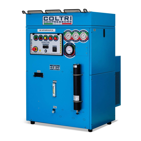
Summary of Contents for Coltri Sub MCH 13/ET Compact
- Page 1 Special equipment and compressors for underwater activities High Pressure Compressors High Pressure Compressors VERSION: English NSTRUCTION ANUAL Revision: DOC MCH 13-16-26-32/ET-04-00...
- Page 2 USE IN BRIEF USE IN BRIEF USE IN BRIEF USE IN BRIEF USE IN BRIEF Use in brief ............................. 7 1 1 1 1 1 GUARANTEE ARANTEE ARANTEE ARANTEE AND AND ASSIST ASSIST ASSISTANCE ASSIST ANCE ANCE ANCE ARANTEE ASSIST ANCE Guarantee ..........................
- Page 3 5 5 5 5 5 UNPA A A A A CKING CKING CKING AND HANDLING AND HANDLING THE MA THE MA CHINE CHINE CKING CKING AND HANDLING AND HANDLING AND HANDLING THE MA THE MA THE MACHINE CHINE CHINE Unpacking the machine ......................25 Pack contents ........................
- Page 4 PUTTING PUTTING THE MA THE MA CHINE OUT OF OPERA CHINE OUT OF OPERA TION TION PUTTING PUTTING PUTTING THE MA THE MA THE MACHINE OUT OF OPERA CHINE OUT OF OPERA CHINE OUT OF OPERATION TION TION AND DISMANTLING THE MACHINE AND DISMANTLING THE MACHINE AND DISMANTLING THE MACHINE AND DISMANTLING THE MACHINE...
- Page 5 ARE P ARE P SPARE P ARE P ARE PAR ARTS 14.1 Exploded view of the machine parts .................. 69 Monobloc .......................... 70 Pistons rod unit ......................... 72 Cylinders unit ........................74 Head unit .......................... 76 Cooling pipes ........................78 Filtering system ........................
- Page 6 To make the manual easier to read, the following terms have been adopted: DANGER The term DANGER is used when failure to comply with the regulations or tampering with the parts could lead to serious injury or even death. WARNING The term WARNING is used when failure to comply with the instructions could cause damage to the machine and other parts associated with the same or to the surrounding area.
- Page 7 USE IN BRIEF USE IN BRIEF USE IN BRIEF USE IN BRIEF USE IN BRIEF The following information must be referred to and applied only when this manual and the “Safety regulations” manual have been read and their contents have been understood and assimilated.
- Page 8 1 1 1 1 1 ARANTEE ARANTEE ASSIST ASSIST ANCE ANCE GUARANTEE ARANTEE ARANTEE AND AND ASSIST ASSIST ASSISTANCE ANCE ANCE Guarantee AEROTECNICA COLTRI S.r.l. guarantees its compressors against any design or manufacturing defect or fault and against any fault in the materials for a period of twelve months from the delivery of the machine.
-
Page 9: Table Of Contents
2 2 2 2 2 TECHNICAL DESCRIPTION TECHNICAL DESCRIPTION TECHNICAL DESCRIPTION TECHNICAL DESCRIPTION TECHNICAL DESCRIPTION This chapter provides a technological description of the machine and its main components. Operating principle ......................10 Description of the pump unit .................... 11 2.2.1 Monobloc unit ......................12 2.2.2 Head unit ........................ -
Page 10: Operating Principle
Operating principle Operating principle Operating principle Operating principle Operating principle The refill stations in the “Compact” series are of the semi-soundproofed type (model MCH 13-16/ET) (Fig. 2) (model MCH 26-32/ET) (Fig. 1). Model MCH 13-16/ET is fitted with a compressor (Fig. -
Page 11: Description Of The Pump Unit
The intake air contains a certain degree of humidity according to atmospheric conditions. During the compression and subsequent cooling, the humidity condenses and together with the particles of lubricating oil forms a milky white emulsion that precipitates into the separators. The compression diagram is included in chapter 13. -
Page 12: Monobloc Unit
Monobloc unit Monobloc unit Monobloc unit Monobloc unit Monobloc unit 2.2.1 2.2.1 2.2.1 2.2.1 2.2.1 The gooseneck, the pistons and the cylinders also form a part of this unit. The monobloc (Fig. 7) is made of aluminium alloy, the two flanges with the ball and roller bearings that support the gooseneck are oil- tight with the monobloc due to the O-Rings fitted. -
Page 13: Head Unit
Head unit (Fig. 10) Head unit (Fig. 10) Head unit (Fig. 10) Head unit (Fig. 10) Head unit (Fig. 10) 2.2.2 2.2.2 2.2.2 2.2.2 2.2.2 The head unit includes the discharge and intake valves. The head of the 1 stage is of a lamellar type and includes both the intake and the discharge. -
Page 14: Lubrication Unit
2.2.4 2.2.4 2.2.4 2.2.4 2.2.4 Lubricating unit Lubricating unit Lubricating unit Lubricating unit Lubricating unit Lubrication is carried out by means of a tang screwed into the end part of the connecting rods of the 2 and 3 stages (Fig. 11). The 3 high pressure stage is lubricated by oil vapours. -
Page 15: Filters
Filters Filters Filters Filters Filters 2.2.7 2.2.7 2.2.7 2.2.7 2.2.7 INTAKE FILTER (Fig. 13) The suction filter is coupled directly to the lid of the 1 stage head. The intake filter consists of a cylindrical aluminium casing provided with a screw cap that holds the filtering cartridge. -
Page 16: Machine Control
F F F F Fr r r r r ame and sound-pr ame and sound-pr ame and sound-pr ed casing (Fig ed casing (Fig..15-16) ed casing (Fig 15-16) 15-16) 2.2.8 2.2.8 2.2.8 ame and sound-pr ame and sound-proof oofed casing (Fig ed casing (Fig... - Page 17 MCH 26-32/ET This model also has the same control buttons as for model MCH 13-16/ET. For model MCH 26-32/ET, the same controls are doubled up on two independent control panels (Fig. 18) which each control one of the two pump units present inside the refill station.
- Page 18 3 3 3 3 3 TECHNICAL CHARACTERISTIC TECHNICAL CHARACTERISTIC TECHNICAL CHARACTERISTIC TECHNICAL CHARACTERISTIC TECHNICAL CHARACTERISTIC This chapter provides some technical information concerning the machine. Technical characteristics of the pump unit ............... 18 3.1.1 Machine series MCH 13-16-26-32/ET ................. 18 3.1.2 Sizes and weights ..................... 19 Noise ...........................
- Page 19 3.1.2 3.1.2 3.1.2 MCH 13-16/ET COMPACT MCH 26-32/ET COMPACT Table 2 MODEL A (mm) B (mm) C (mm) Weight (Kg.) MCH 13/ET Compact MCH 16/ET Compact MCH 26/ET Compact 1330 MCH 32/ET Compact 1330 Noise Noise Noise Noise Noise The Compact series of compressors have been designed and built with the objective of reducing acoutsic pressure to a minimum.
- Page 20 The reading of the machine noise level was taken from the “operator’s work place” (Fig. 20), with the following methods and results: Table 3 METHODS OF MEASUREMENT ISO 3746 dB(A) 79,4 dB(A) 81 dB(A) 72,4 dB(A) 75 Level of acoustic pressure at the operator’s work place Level of acoustic power dB(A) 91,5 dB(A) 94,5...
- Page 21 PRECA PRECA PRECAUTIONS FOR USE UTIONS FOR USE UTIONS FOR USE UTIONS FOR USE AND PRECA PRECA UTIONS FOR USE 4 4 4 4 4 MAINTENANCE MAINTENANCE MAINTENANCE MAINTENANCE MAINTENANCE Refer to the specific “Safety Regulation Manual” which is supplied enclosed with this manual (and which forms an integral part of the same).
- Page 22 4.1.1 4.1.1 Safety devices Safety devices Safety devices Safety devices Safety devices 4.1.1 4.1.1 4.1.1 The MCH 13-16/ET Compact (Fig. 22) and MCH 26-32/ET Compact (Fig. 23) series of compressors are equipped with a series of protection guards fitted with screws and safety devices to guarantee the operator’s safety, by limiting the work area and ensuring good operating conditions.
- Page 23 Table 1 POSITION SAFETY DEVICE DESCRIPTION INSPECTION Safety valves. Protect the third stage and the cylinders The safety valve must be checked at from being overfilled; it is calibrated each refill; start up the compressor with during the inspection of the compres- the cylinder valves closed and the end sors.
- Page 24 4.1.2 4.1.2 Residual risk areas Residual risk areas Residual risk areas Residual risk areas Residual risk areas 4.1.2 4.1.2 4.1.2 In some areas of the machine there are some residual risks that could not be eliminated during the design phase or protected by guards due to the particular operation of the compressors model MCH 13-16-26-32/ET Compact (Fig.
- Page 25 5 5 5 5 5 UNPA A A A A CKING CKING CKING AND HANDLING AND HANDLING THE MA THE MA CHINE CHINE CKING CKING AND HANDLING AND HANDLING AND HANDLING THE MA THE MA THE MACHINE CHINE CHINE This chapter provides the instructions necessary for unpacking and handling the machine. Unpacking the machine .....................
- Page 26 Pack contents Pack contents Pack contents Pack contents Pack contents The standard equipment with which the machine is supplied is: - 2 refill hoses measuring 1200 mm with valve for model MCH 13-16/ET Compact and 4 hoses for model MCH 26-32/ET Compact; - operating and maintenance booklet;...
- Page 27 6 6 6 6 6 I I I I I N S T N S T N S T A L L A A L L A TION TION N S T N S TA L L A A L L A A L L ATION TION TION...
- Page 28 4 Position the machine at a minimum distance of 1 m. from the surrounding walls and at a distance of not less than 1.5 m. from the ceiling in order not to compromise the proper operation and cooling of the pump unit (Fig.
- Page 29 MCH 13-16/ET Compact To connect the extension, proceed as follows: MCH 13-16/ET Compact 1 Remove the upper protective cover by unscrewing the fixing screws (Fig. 31). MCH 26-32/ET Compact MCH 26-32/ET Compact 1 Remove the left-hand side protective cover (looking at the compressor from the front), by unscrewing the fixing screws (Fig.
- Page 30 2 Connect the extension pipe to the connector (Fig. 33) (2 in model MCH 26-32/ET Compact). 3 Pass the pipe through the hole located in the rear guard (Fig. 34-35-36) (2 in model MCH 26-32/ET Compact). MCH 13-16/ET Compact MCH 26-32/ET Compact Installation...
- Page 31 MCH 26-32/ET Compact 4 Fit the additional intake filter on the end of the extension pipe (Fig. 37) (2 in model MCH 26-32/ET Compact). 5 Position the end of the extension on which the intake filter is fitted (air intake) in a ventilated place protected from atmospheric agents.
- Page 32 7 Make sure that there are no bends or breakages along the length of the pipe (Fig. 39). If the extension should have broken during the connection to the head, it must be replaced. WARNING Make sure that the air intake is away from exhaust fumes given off by internal-combustion engines or harmful fumes.
- Page 33 4 Tighten the hoses to the machine with a torque wrench setting of 15Nm (Fig. 41). NOTE: - the hoses should be replaced every so often (every year or every 1000 hours) or when they show signs of being scratched. For this purpose, check the number of operating hours of the hoses that are to be disconnected (on the hour counter).
- Page 34 7 7 7 7 7 CONTR CONTR OL P OL P ANEL ANEL CONTR CONTR CONTROL P OL P OL PANEL ANEL ANEL This chapter provides a description of the functions carried out by the various devices fitted on the control panel.
- Page 35 Indication and control devices Indication and control devices Indication and control devices Indication and control devices Indication and control devices Apart from the control panel, the front panel of the machine is also fitted with some devices to control the pressure, the discharge of the condensate, the strainer filter and the level of the lubricating oil (Fig.
- Page 36 8 8 8 8 8 T UP T UP STAR ART UP T UP T UP This chapter describes the operations regarding the machine start up phase. The following instructions presume that the operator has already become familiar with the precautions given in Chapter 4 “Precautions for use and maintenance”...
- Page 37 MCH 13-16/ET Compact The oil is added by removing the cap marked with the word “OIL” (Fig. 48) for model MCH 13-16/ET, while for model MCH 26-32/ET the two oil caps located on the upper cover of the machine (Fig. 49) and marked with the letters “A” and “B” must be unscrewed.
- Page 38 2 Turn the machine on by moving the general switch to the “ON” position. Check that the machine has been switched on by looking to see the red light of the “OFF” button (Fig. 51). 3 Run the compressor for about 10 minutes then leave it at a standstill for 20 minutes.
- Page 39 5 The operation to check the level of the lubricant must be carried out when the machine arrives and then before starting up the compressor. It must be remembered that if the level is too low or too high it may compromise the running of the compressor. 6 In order to check the correct connection of the electrical phases, the engine should be turned on and the direction of rotation checked.
- Page 40 9 9 9 9 9 U S E E E E E This chapter describes the operations required for refilling the cylinders. The following instructions presume that the operator has already become familiar with the precautions given in Chapter 4 “Precautions for use and maintenance” and that the machine has been started up according to the instructions given in the previous chapter.
- Page 41 After refilling, the cylinders must not be emptied completely, even during winter storage, to prevent damp air from getting in (Fig. 58). 3 Check the condition of the hoses and the relative connectors. See paragraph 6.2.2 “Connecting the refill hoses”. AUTOMATIC CONDENSATE DISCHARGE MCH 13-16/ET Compact 4 For the models provided with an automatic...
- Page 42 MANUAL CONDENSATE DISCHARGE 4 Place a container under the two condensa- te sniffle valves and then proceed with the manual discharge by turning on the repsective taps (Fig. 61). For models MCH 26-32/ET Compact the operation must be carried out twice (4 valves) (Fig.
- Page 43 Refilling the cylinders Refilling the cylinders Refilling the cylinders Refilling the cylinders Refilling the cylinders During this operation, the operator’s position is that shown in chapter 3.2 “Noise”. WARNING During the refilling of the cylinders it is compulsory for staff who are not involved with the task to keep a distance of at least three metres.
- Page 44 1 Fit hose attachment “1” to the cylinder valves and turn on tap “2” (Fig. 66). 2 Turn on the cylinder tap (Fig. 67). 3 Start up the compressor by pressing the corresponding button. (General switch on “ON” and then press the green button) (Fig. 68). 4 When the cylinder has been filled, the compressor is stopped automatically by the pressure switch.
- Page 45 5 Turn off the cylinder tap and that of the hoses (Fig. 69). 6 Press the pressure bleed button on the refill tap and then disconnect the cylinder attachment (Fig. 70). If an emergency situation should arise during the refilling of the cylinders, press the “OFF” button located on the control board (Fig.
- Page 46 PUTTING PUTTING THE MA THE MA CHINE OUT OF OPERA CHINE OUT OF OPERA TION TION PUTTING PUTTING PUTTING THE MA THE MA THE MACHINE OUT OF OPERA CHINE OUT OF OPERA CHINE OUT OF OPERATION TION TION DISMANTLING TH DISMANTLING TH E MACHINE E MACHINE...
- Page 47 It is important to remember that the loading and discharge of waste oil, special waste products and toxic or harmful waste products deriving from industrial or artisan processes must be registered. The collection of waste oils and special toxic or harmful waste products must be carried out by specially authorized companies.
- Page 48 INTENANCE INTENANCE M A INTENANCE INTENANCE INTENANCE This chapter includes instructions concerning the preventive, routine and additional maintenance operations. In the specifications for the preventive maintenance operations for the various devices indication is also given of the frequency of such procedures. Before consulting the chapter, read Chapter 4 “Precautions for use and maintenance”...
- Page 49 During the guarantee period no responsibility is taken for any damage or operating faults due to a failure to comply with the regulations in force. The following paragraph enables all the routine and additional maintenance operations carried out on the machine to be recorded.
-
Page 50: Changing The Lubricant Oil
Changing the lubricant oil (T Changing the lubricant oil (Ta a a a a b b b b b le 2) Changing the lubricant oil (T le 2) le 2) 11.3 11.3 Changing the lubricant oil (T Changing the lubricant oil (T le 2) le 2) 11.3... - Page 51 3 Open the oil discharge two taps (Fig. 73) and discharge all the oil in the sumps. 4 Close the discharge tap and replace the hexagonal closing cap. 5 Carry out the filling operations as described in chapter 8 “Start up”. WARNING To dispose of waste oils follow the instructions given in chapter 10.2 “Disposal of waste products”...
-
Page 52: Checking The Transmission Belt
11.4 11.4 11.4 Checking the transmission belt Checking the transmission belt Checking the transmission belt 11.4 11.4 Checking the transmission belt Checking the transmission belt The drive belt control involves measuring the flex herself. This operation must be carried out every 250 machine operating hours as described below: 1 Remove the protective cover as shown on figures 74 and 75, by unscrewing the fixing... - Page 53 2 By exerting a pressure of at least 5 Kg., check that the belt does not flex by more than 5 mm. compared to its original position (Fig. 76). If this distance should exceed 5 mm., intervene by loosening the motor fastening screws (Fig.
- Page 54 MCH 13-16/ET Compact The filter must be replaced every 125 operating hours with the following procedure: MCH 13-16/ET Compact 1 Remove the upper protective cover by unscrewing the securing screws (Fig. 78). MCH 26-32/ET Compact MCH 26-32/ET Compact 1 Remove the left-hand side protective cover (looking at the compressor from the front), by unscrewing the fixing screws (Fig.
-
Page 55: Active Carbon Filter And Molecular Sieve
3 Remove the filter and replace it with a new one (Fig. 81). To order a new spare filter, refer to chapter 14 “Spare parts”. 4 Refit the safety guard and tighten the screws (see point 1). Active carbon filter and molecular sieve Active carbon filter and molecular sieve Active carbon filter and molecular sieve Active carbon filter and molecular sieve... - Page 56 Table 4 N° OF 10 LITRE CYLINDERS TO VOLUME OF DURATION OF MODEL BE REFILLED FILTERED AIR THE FILTER 200 bar 300 bar cu.m. hours MCH 13/ET MCH 16/ET MCH 26/ET MCH 32/ET Check the sealing O-Rings and replace them if they are damaged. Leave the cartridge in the filter when the compressor is not in use.
-
Page 57: Refill Hose
unscrew the used cartridge from the internal cap (Fig. 84) and then screw in the new one; screw up the internal cap having lubricated or replaced the sealing O-Rings if they are worn and having lubricated the threads of the external cap using silicone grease. WARNING The used active carbon filter cannot be disposed of together with urban waste. -
Page 58: Heads
11.8 11.8 Intak Intak e and disc e and disc har g g g g g e v 11.8 11.8 11.8 Intak Intak Intake and disc e and disc e and dischar e v alv alves The 2 stage intake valve can be removed for maintenance purposes while those of the 1 (only discharge) and 3 stages must be entirely replaced. -
Page 59: Cylinders
The head of the 2 stage (B) is made of aluminium (Fig. 86), the valves are screwed in; the intake valve inside is removed using a special pin wrench while the discharge valve is on the outside and is removed with a non-adjustable wrench or a box wrench. -
Page 60: Maintenance Programme
Maintenance programme Maintenance programme 11.11 11.11 11.11 Maintenance programme Maintenance programme Maintenance programme 11.11 11.11 Use the following pages to note the routine and additional maintenance operations carried out on the machine. If the maintenance programme is filled in accurately, it will be easier for the technician to intervene if assistance is required. - Page 61 Date: ..............................Operation carried out: ......................... Date: ..............................Operation carried out: ......................... Date: ..............................Operation carried out: ......................... Date: ..............................Operation carried out: ......................... Date: ..............................Operation carried out: ......................... Date: ..............................Operation carried out: ......................... Date: ..............................Operation carried out: ......................... Date: ..............................
- Page 62 OUBLESHOO OUBLESHOO TING TING TROUBLESHOO OUBLESHOO OUBLESHOOTING TING TING This chapter describes the faults that may arise during machine operation. For each fault, the cause and the solution to be adopted are specified. 12.1 List of faults ........................62 12.1 12.1 12.1 12.1...
- Page 63 MACHINE DIAGRAMS MACHINE DIAGRAMS MACHINE DIAGRAMS MACHINE DIAGRAMS MACHINE DIAGRAMS This chapter provides the plans and diagrams of the systems installed on the machine. 13.1 Compression diagram ......................63 13.2 Electrical diagram ......................64 Compression diagram Compression diagram 13.1 13.1 Compression diagram Compression diagram Compression diagram...
- Page 64 13.1 13.1 Electrical diagram Electrical diagram Electrical diagram 13.1 13.1 13.1 Electrical diagram Electrical diagram The model “MCH 13-16/ET Compact” compressor The model “MCH 13-16/ET Compact” compressor The model “MCH 13-16/ET Compact” compressor The model “MCH 13-16/ET Compact” compressor The model “MCH 13-16/ET Compact” compressor Machine diagrams...
- Page 65 The model “MCH 26-32/ET Compact” compressor The model “MCH 26-32/ET Compact” compressor The model “MCH 26-32/ET Compact” compressor The model “MCH 26-32/ET Compact” compressor The model “MCH 26-32/ET Compact” compressor Machine diagrams...
- Page 66 The model “MCH 26-32/ET Compact” compressor The model “MCH 26-32/ET Compact” compressor The model “MCH 26-32/ET Compact” compressor The model “MCH 26-32/ET Compact” compressor The model “MCH 26-32/ET Compact” compressor Machine diagrams...
- Page 67 POS. TO BE READ GENERAL MAIN SWITCH PRIMARY AUSILIARIES PROTECTION SWITCH AUSILIARIES TRASFORMER (380/220 OR 220/220) SECONDARY AUSILIARIES PROTECTION SWITCH PRESSURE SWITCH MECHANICAL PROTECTION CONTROL MECHANICAL PROTECTION CONTROL MOTOR M1 OVERLOAD RELEASE MOTOR PROTECTION SWITCH MOTOR CONTROL CONTACTOR MOTOR STOPPING PUSH BOTTON STOPPING PUSH BOTTON PURGE PUSH BOTTON READY STATE RUNNING SIGNALING (GREEN)
- Page 69 SPARE P ARE P ARE P ARE PAR ARTS ARE P 14.1 Exploded view of the machine parts ................69 Monobloc ........................70 Pistons rod unit ....................... 72 Cylinders unit ........................74 Head unit ......................... 76 Cooling pipes ........................78 Filtering system .......................
-
Page 71: Monobloc
Monobloc Monobloc Monobloc Monobloc Monobloc POS. CODE DESCRIPTION 13-00-0001 MONOBLOC 13-01-0008 FIRST STAGE TIE ROD 13-03-0016 THIRD STAGE TIE ROD 13-02-0040 SECOND STAGE TIE ROD 13-00-0042 FLANGE ROLLER BEARING NU305 13-00-0050 FILTER SIDE FLANGE 13-00-0052 OIL DISCHARGE EXTENSION 13-00-0021 CORNER ¹/ PIPE FITTING 8 mm. - Page 72 118/A 117/A 113/A 112/A 116/A...
-
Page 73: Pistons Rod Unit
Pistons rod unit Pistons rod unit Pistons rod unit Pistons rod unit Pistons rod unit POS. CODE DESCRIPTION 13-00-0072 SEEGER RETAINING RING A 30 13-00-0098 GOOSENECK 13-00-0099 KEY 13-00-0100 COUNTERWEIGHT 13-00-0101 8 mm. SELF-LOCKING NUT 13-00-0104 8x65 TCE SCREW 13-00-0105 THIRD STAGE CONNECTING ROD 13-00-0106 SPACER 13-01-0107 FIRST STAGE CONNECTING ROD 13-00-0106 SPACER... -
Page 74: Cylinders Unit
Cylinders unit Cylinders unit Cylinders unit Cylinders unit Cylinders unit Spare parts... - Page 75 Cylinders unit Cylinders unit Cylinders unit Cylinders unit Cylinders unit POS. CODE DESCRIPTION 13-01-0002 FIRST STAGE 88 mm. CYLINDER 002/A 16-01-0002 FIRST STAGE 95 mm. CYLINDER 13-01-0007 FIRST STAGE CYLINDER O-RING 13-00-0015 THIRD STAGE CYLINDER O-RING 13-02-0017 THIRD STAGE GUIDING CYLINDER 13-00-0018 8 mm.
- Page 76 003/A...
-
Page 77: Head Unit
Head unit Head unit Head unit Head unit Head unit POS. CODE DESCRIPTION 13-01-0003 FIRST STAGE 88 mm. GASKET 003/A 16-01-0003 FIRST STAGE 95 mm. GASKET 13-01-0004 FIRST STAGE HEAD WITH VALVES 13-01-0005 FIRST STAGE GASKET 13-01-0006 FIRST STAGE HEAD COVER 13-00-0009 8 mm. -
Page 79: Cooling Pipes
Cooling pipes Cooling pipes Cooling pipes Cooling pipes Cooling pipes POS. CODE DESCRIPTION 13-03-0023 6 mm. COOLING PIPE 13-00-0036 8 mm. PIPE 13-00-0074 FAN-HOLDING HUB 13-00-0075 8x30 TCE SCREW 13-00-0077 COOLING FAN 13-00-0079 12 mm. FLAT WASHER 13-00-0080 12x35 TCE SCREW 13-00-0081 10x40 TCE SCREW 13-00-0082 FAN FLANGE 13-00-0083 GALVANIZED PIPE-HOLDING BRACKET... -
Page 80: Filtering System
Filtering system Filtering system Filtering system Filtering system Filtering system Spare parts... - Page 81 Filtering system Filtering system Filtering system Filtering system Filtering system POS. CODE DESCRIPTION 13-00-0097 CLEANER FILTER 13-00-0152 VITE 8x30 TCE 13-00-0153 VITE 8x12 TCE 13-00-0154 UPPER FILTER CAP 13-00-0155 FILTER CAP O-RING 13-00-0156 INTERNAL FILTER CAP 13-00-0155 FILTER CAP O-RING 13-00-0158 FILTER CARTRIDGE O-RING 13-00-0155 FILTER CAP O-RING 13-00-0160 LOWER FILTER CAP...
-
Page 82: Mch 13-16/Et Condensate Trap
MCH 13-16/ET condensate trap MCH 13-16/ET condensate trap MCH 13-16/ET condensate trap MCH 13-16/ET condensate trap MCH 13-16/ET condensate trap Spare parts... - Page 83 MCH 13-16/ET condensate trap MCH 13-16/ET condensate trap MCH 13-16/ET condensate trap MCH 13-16/ET condensate trap MCH 13-16/ET condensate trap POS. CODE DESCRIPTION 13-03-0023 6 mm. COOLING PIPE 13-00-0036 8 mm. PIPE 13-00-0089 10 mm. 2nd-3rd STAGE COOLING PIPE 13-00-0048 8x25 TCE SCREW 13-00-0092 LOWERED 8x20 TCE SCREW 13-00-0094 FILTER-HOLDING PLATE 13-00-0096 CONDENSATE TRAP...
- Page 84 MCH 26-32/ET MCH 26-32/ET condensate trap condensate trap MCH 26-32/ET MCH 26-32/ET MCH 26-32/ET condensate trap condensate trap condensate trap Spare parts...
-
Page 85: Mch 26-32/Et Condensate Trap
MCH 26-32/ET condensate trap MCH 26-32/ET condensate trap MCH 26-32/ET condensate trap MCH 26-32/ET condensate trap MCH 26-32/ET condensate trap POS. CODE DESCRIPTION 13-03-0023 6 mm. COOLING PIPE 13-00-0036 8 mm. PIPE 13-04-0226 HP 300 mm. PIPE 13-00-0089 10 mm. 2nd-3rd STAGE COOLING PIPE 13-00-0048 8x25 TCE SCREW 13-00-0092 LOWERED 8x20 TCE SCREW 13-00-0094 FILTER-HOLDING PLATE... - Page 86 210/A...
-
Page 87: Mch 13-16/Et
MCH 13-16/ET MCH 13-16/ET MCH 13-16/ET MCH 13-16/ET MCH 13-16/ET POS. CODE DESCRIPTION 13-04-0208 COMPLETE LOCK 13-04-0209 SWITCHBOARD PANEL SC000310 280 BAR PRESSURE SWITCH 210/A SC000315 330 BAR PRESSURE SWITCH 13-04-0211 PRESSURE GAUGE WITH FLANGE 13-04-0217 RELOAD RAMP ALUMINIUM BLOCK 13-04-0221 LP CONDENSATION DISCHARGE SOLENOID VALVE 13-04-0222 HP CONDENSATION DISCHARGE SOLENOID VALVE 13-04-0224 CONDENSATION DISCHARGE ALUMINIUM BLOCK... -
Page 88: Mch 26-32/Et
MCH 26-32/ET MCH 26-32/ET MCH 26-32/ET MCH 26-32/ET MCH 26-32/ET Spare parts... - Page 89 MCH 26-32/ET MCH 26-32/ET MCH 26-32/ET MCH 26-32/ET MCH 26-32/ET POS. CODE DESCRIPTION 13-04-0272 CONDENSATION DISCHARGE CAN COMPLETE WITH PIPE FITTINGS 13-04-0279 VIBRATION DAMPNER WITH DOUBLE ATTACHMENT 13-04-0409 PUMP UNITS REAR PANEL 13-04-0410 COMPACT UPPER PANEL 13-04-0411 OIL REFILL CAP B 13-04-0412 OIL REFILL CAP A 13-04-0413 COMPACT STAY BOLT M6 13-04-0414 COMPACT LEFT-HAND SIDE PANEL...
- Page 90 210/A...
- Page 91 MCH 26-32/ET MCH 26-32/ET front panel front panel MCH 26-32/ET MCH 26-32/ET front panel MCH 26-32/ET front panel front panel POS. CODE DESCRIPTION 13-04-0200 RED STOP BUTTON 13-04-0201 GREEN START BUTTON 13-04-0202 YELLOW CONDENSATION DISCHARGE BUTTON 13-04-0203 OFF PLATE 13-04-0204 ON PLATE 13-04-0205 MANUAL PURGE PLATE 13-04-0207 HOUR COUNTER 13-04-0208 COMPLETE LOCK...
- Page 92 AEROTECNICA COLTRI S.r.l. Registered office: Via Rio Ponale, 7 - 25010 Rivoltella di Desenzano D/Garda - BRESCIA - ITALY Factory: Via Colli Storici, 177 - 25010 San Martino della Battaglia - BRESCIA - ITALY Tel. +39 030 9910297-9910301 - Fax +39 030 9910283 e-mail: coltrisub@coltrisub.it Internet: http://www.coltrisub.it...
Need help?
Do you have a question about the MCH 13/ET Compact and is the answer not in the manual?
Questions and answers