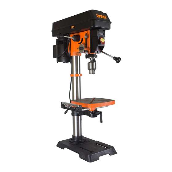
Wen 4214 Operator's Manual
12" variable, with laser crosshair
Hide thumbs
Also See for 4214:
- User manual ,
- Instruction manual (32 pages) ,
- Replacement manual (10 pages)
Advertisement
Table of Contents
- 1 Table of Contents
- 2 Technical Data
- 3 General Safety Rules
- 4 Specific Safety Rules for the Drill Press
- 5 Electrical Information
- 6 Know Your Drill Press
- 7 Assembly and Adjustments
- 8 Operation
- 9 Maintenance
- 10 Troubleshooting
- 11 Replacement Parts
- 12 Exploded View
- Download this manual
See also:
User Manual
Advertisement
Table of Contents

Subscribe to Our Youtube Channel
Related Manuals for Wen 4214


Summary of Contents for Wen 4214
-
Page 2: Table Of Contents
Replacement parts……………………………………………………………………… Part List…………………………………………………………………………………………... Exploded view……………………………………………………………………………… One year limited warranty…………………………………………………………………….. Technical data 12" Variable Speed Drill Press with Laser Crosshair Model # 4214 Motor: 120 V, 60 Hz, 4.8 A Horsepower: 2/3 HP (single phase) Speed: 530–3100 RPM (no load) Chuck capacity: 1/32–5/8"... -
Page 3: General Safety Rules
11. AVOID ACCIDENTAL START-UPS. Make sure the power switch is in the OFF position before plugging in the power cord. 12. REMOVE ADJUSTMENT TOOLS. Always make sure all adjustment tools are removed from the drill press before turning it on. 4214 WENPRODUCTS.COM... - Page 4 • Do not project the laser beam into the eyes of others. • Always ensure the laser beam is aimed at a workpiece without reflective surfaces as the laser beam could be projected into your eyes or the eyes of others. 4214 WENPRODUCTS.COM...
-
Page 5: Specific Safety Rules For The Drill Press
14. Should any part of the drill press be missing, damaged, or any electrical component fail to perform properly, shut the power OFF and unplug the drill press. Replace missing, damaged, or failed parts before resuming operation. 15. Before leaving the machine, shut the power off, remove the drill bit, and clean the table. 4214 WENPRODUCTS.COM... -
Page 6: Electrical Information
2. Properly grounded outlet 3 - Grounding prong 3. Grounding prong CAUTION: In all cases, make certain the outlet in question is properly grounded. If you are not sure if it is, have a licensed electrician check the outlet. 4214 WENPRODUCTS.COM... - Page 7 OFF position and the electric current is rated the same as the current stamped on the motor nameplate. Running at a lower voltage will damage the motor. WARNING: This tool must be grounded while in use to protect the operator from electric shock. 4214 WENPRODUCTS.COM...
-
Page 8: Know Your Drill Press
Extension wing with Depth scale K Crank handle integrated rollers Chuck Column support Support lock handle Table Base Speed control handle Feed handles N Table lock handle Power cord Housing cover screw Bevel lock bolt Housing cover Bevel scale 4214 WENPRODUCTS.COM... -
Page 9: Assembly And Adjustments
M Hex keys (2) D Base Feed and speed handles (4) Chuck arbor Clamp assembly Chuck LED bulb G Extension wing with integrated rollers Table adjustment wrench H Chuck key Wedge Wing knobs (2) Laser enhancing glasses Table lock handles (2) 4214 WENPRODUCTS.COM... - Page 10 8. Thread the table support lock handle into the rear of the table support bracket (not shown). 9. Position the table (5) in the same direction as the base, install the table, and tighten the table lock handle (4). 4214 WENPRODUCTS.COM...
- Page 11 Speed handle (Fig. 7) 1. Insert the feed handle (1) into the threaded opening on the speed hub (2). 2. Manually tighten handle into opening. Fig. 7 4214 WENPRODUCTS.COM...
- Page 12 IMPORTANT: If the stand or workbench has a tendency to move during operation, fasten the workbench securely to the floor. LED bulb (Fig. 9) Insert the LED bulb (1) into the socket (2) in the motor head assembly. Fig. 9 4214 WENPRODUCTS.COM...
- Page 13 2. Slide the wedge (3) into the opening in the quill. Tap on the wedge using a hammer (4; not included). The chuck and arbor will drop out. Note: To avoid possible damage to the drill or chuck, be prepared to catch the chuck as it falls. 4214 WENPRODUCTS.COM...
- Page 14 1. Insert the two rods (1) of the table extension into the two channels (2) at the side of the table. 2. Place a wing knob (3) in the opening on the bottom of each channel and tighten to secure the extension to the table. 4214 WENPRODUCTS.COM...
- Page 15 6. Tighten the bevel lock when square. Note: Adjustments for the correct function of your drill press return spring have been done at the factory. Please do not modify them. However, prolonged use of the drill press may make some readjustments necessary. 4214 WENPRODUCTS.COM...
- Page 16 (3) counterclockwise. b. Rotate the laser light housing (4) until the two laser lines intersect where the drill meets the workpiece. DO NOT stare directly at the laser lines. 5. Re-tighten the adjustment set screws (3). Fig. 18 4214 WENPRODUCTS.COM...
- Page 17 1. Loosen the lock nut (1). 2. Without obstructing the upward and downward motion of the spindle, turn the screw (2) clockwise to eliminate the "play". Note: A little bit of "play" is normal. 3. Tighten the lock nut (1). 4214 WENPRODUCTS.COM...
- Page 18 4. Position the clamp as needed on the table and fully tighten the lock handles to secure the clamp. 5. Loosen the wing nut (4) to move the small support on the front of the clamp into position. Tighten the wing nut to secure. 4214 WENPRODUCTS.COM...
-
Page 19: Operation
(3) of the column as illustrated, or be clamped (4; not included) to the table. Note: For small workpieces that cannot be clamped to the table, use a drill press vise (not included). The vise must be clamped or bolted to the table to avoid injury. 4214 WENPRODUCTS.COM... - Page 20 1. Turn the feed handles until the quill is at the desired height and hold it there. 2. Rotate the lower depth knob (3) until it rests against the bottom of the metal gauge support (4). 4214 WENPRODUCTS.COM...
- Page 21 (2) until it meets the metal support. 4. Rotate the upper (1) depth scale lock knob until it meets the lower knob (2). The chuck and the drill bit will now be stopped at the distance selected on the depth scale. 4214 WENPRODUCTS.COM...
- Page 22 Pull down on the feed handles with only enough force to allow the drill bit to cut. Feeding too rapidly might stall the motor, cause the belt to slip, damage the workpiece, or break the drill bit. Feeding too slowly will cause the drill bit to heat up and burn the workpiece. 4214 WENPRODUCTS.COM...
- Page 23 RANGE Drill bit size Drill bit size Drill bit size (RPM) inches inches inches 2000–3100 7/32 3/32 1400–2000 16.0 11/32 8.75 5/32 1000–1400 22.0 15/32 12.0 800–1000 1 1/4 31.75 11/16 17.5 530–800 1 5/8 41.4 19.0 16.0 4214 WENPRODUCTS.COM...
-
Page 24: Maintenance
Lubricate the table bracket and locking knobs if they become difficult to use. CAUTION: All servicing of the drill press should be performed by a qualified service technician. 4214 WENPRODUCTS.COM... -
Page 25: Troubleshooting
• Clean the tapered surface of both the chuck and Chuck falls off spindle. 1. Dirt, grease, or oil on the the spindle with a household detergent. See To tapered surface on the spindle or in the chuck. install the chuck in Assembly. 4214 WENPRODUCTS.COM... - Page 26 2. Incorrect fuses or circuit breakers. the circuit. • Turn off other machines and retry. 3. Overloaded circuit. • Check the power line for the proper voltage. Use 4. Low voltage. another circuit or have a qualified electrician upgrade the service. 4214 WENPRODUCTS.COM...
-
Page 27: Replacement Parts
Replacement Parts Use only WEN® replacement parts. Use of any other parts may cause damage to your machine. When ordering replacement parts, please provide the model number, part number, and description. 4214... - Page 28 Parts list Item# Part# Description Item# Part# Description 4214-001 Pan Head ScrewM4x8 4214-045 Spring 4214-002 Slider 4214-046 Shaft 4214-003 Baffle 4214-047 Laser Beam Device 4214-004 Base 4214-048 Bulb 4214-005 Column Clamp 4214-049 Pan Head ScrewM3x8 4214-006 Hex. Screw M8x8 4214-050...
- Page 29 Parts list (continued) Item# Part# Description Item# Part# Description 4214-089 Switch Box 4214-114 Retaining Ring 4214-090 Key Switch 4214-115 Ball Bearing 4214-091 Light Switch 4214-116 4214-092 Adjust Nut 4214-117 Retaining Ring 4214-093 Washer 4214-118 Retaining Ring 4214-094 4214-119 Motor Pulley...
-
Page 30: Exploded View
Exploded view 4214 WENPRODUCTS.COM... - Page 31 (2) years from date of purchase. Ninety (90) days for all WEN Products, if the tool is used for professional or commercial use.
- Page 32 4214 WENPRODUCTS.COM...
Need help?
Do you have a question about the 4214 and is the answer not in the manual?
Questions and answers