Wen 4214 User Manual
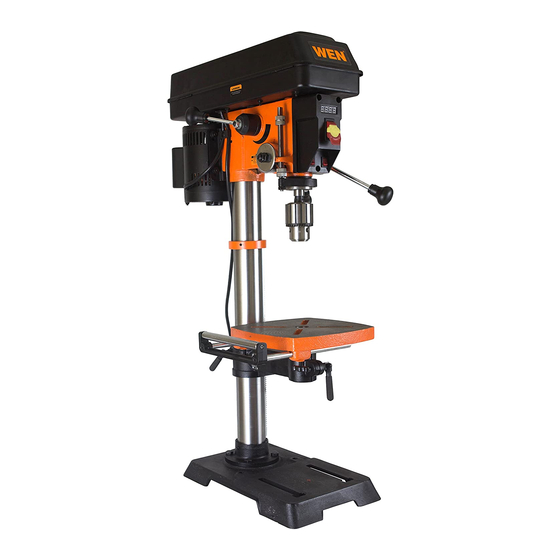
12" variable speed drill press
Hide thumbs
Also See for 4214:
- User manual ,
- Operator's manual (32 pages) ,
- Instruction manual (32 pages)
Table of Contents
Advertisement
Your new tool has been engineered and manufactured to WEN's highest standards for dependability,
ease of operation, and operator safety. When properly cared for, this product will supply you years
of rugged, trouble-free performance. Pay close attention to the rules for safe operation, warnings,
and cautions. If you use your tool properly and for intended purpose, you will enjoy years of safe,
reliable service.
12˝ VARIABLE SPEED
DRILL PRESS
IMPORTANT:
NEED HELP? CONTACT US!
Have product questions? Need technical support?
Please feel free to contact us at:
800-232-1195
techsupport@wenproducts.com
WENPRODUCTS.COM
Model # 4214
bit.ly/wenvideo
(M-F 8AM-5PM CST)
2015
Advertisement
Table of Contents

Related Manuals for Wen 4214


Summary of Contents for Wen 4214
- Page 1 IMPORTANT: Your new tool has been engineered and manufactured to WEN’s highest standards for dependability, ease of operation, and operator safety. When properly cared for, this product will supply you years of rugged, trouble-free performance. Pay close attention to the rules for safe operation, warnings, and cautions.
-
Page 2: Table Of Contents
Electrical Information Know Your Drill Press Assembly and Adjustments Operation Maintenance Troubleshooting Exploded View and Parts List Warranty TECHNICAL DATA 4214 Model Number: 120 V, 60 Hz, 5 A Motor: 580-3200 RPM (no load) Speed: 1/8--5/8˝ Chuck Capacity: Stroke: 3-1/8˝... -
Page 3: General Safety Rules
GENERAL SAFETY RULES Safety is a combination of common sense, staying alert and knowing how your item works. SAVE THESE SAFETY INSTRUCTIONS. WARNING: To avoid mistakes and serious injury, do not plug in your tool until the following steps have been read and understood. 1. -
Page 4: Specific Safety Rules For Drill Press
GENERAL SAFETY RULES 14. NEVER STAND ON A TOOL. Serious injury could result if the tool tips or is accidentally hit. DO NOT store anything above or near the tool. 15. DO NOT OVERREACH. Keep proper footing and balance at all times. Wear oil-resistant rubber-soled foot- wear. -
Page 5: Electrical Information
SPECIFIC RULES FOR DRILL PRESS 10. Always stop the drill before removing scrap pieces from the table. 11. Use clamps or a vise to secure a workpiece to the table. This will prevent the workpiece from rotating with the drill bit. 12. - Page 6 ELECTRICAL INFORMATION GUIDELINES FOR USING EXTENSION CORDS Make sure your extension cord is in good condition. When using an extension cord, be sure to use one heavy enough to carry the current your product will draw. An undersized cord will cause a drop in line voltage resulting in loss of power and overheating.
-
Page 7: Know Your Drill Press
KNOW YOUR DRILL PRESS Fig. 1 Digital Speed Readout Column Laser ON/OFF Switch ON/OFF Switch Rack LED Worklight Switch Depth Scale Crank Handle Extension Wing with Integrated Chuck Column Support Rollers Table Base Support Lock Handle Feed Handles Table Lock Handle Speed Control Handle Housing Cover Screw Bevel Lock Bolt... -
Page 8: Assembly And Adjustments
ASSEMBLY AND ADJUSTMENTS UNPACKING (Fig. 2) Unpack the drill press and all of its parts. Compare against the list below. Do not discard the carton or any packaging until the drill press is completely assembled. To protect the drill press from moisture, a protective coating has been applied to the machine’s surfaces. Remove this coating with a soft cloth moistened with kerosene or WD-40®. - Page 9 ASSEMBLY AND ADJUSTMENTS WARNING: If any part is missing or damaged, do not plug the drill press in until the missing or damaged part is repaired or replaced. The column assembly (column, column support, rack, rack collar, and table support bracket) must be attached to the base.
- Page 10 ASSEMBLY AND ADJUSTMENTS DRILL PRESS HEAD TO COLUMN (Fig. 5) CAUTION: The drill press head is heavy. To avoid injury, two people should lift it into position. 1. Carefully lift the drill press head assembly (1) and position it over the column (2). 2.
- Page 11 ASSEMBLY AND ADJUSTMENTS MOUNT THE DRILL PRESS (Fig. 8) The drill press must be securely fastened through the mounting holes to a stand or workbench with heavy-duty fasteners. This will prevent the drill press from tipping over, sliding, or walking during operation.
- Page 12 ASSEMBLY AND ADJUSTMENTS RAISE OR LOWER THE TABLE (Fig. 11) 1. Loosen the support lock handle (1) and turn the crank handle (2) until the table is at the desired height. 2. Tighten the support lock handle before drilling. ROTATE THE TABLE (Fig. 11) 1.
- Page 13 ASSEMBLY AND ADJUSTMENTS WARNING: To avoid injury, make sure the chuck key is removed from the chuck before starting any drilling operation. INSTALLING A DRILL BIT (Fig. 13) 1. Place the chuck key (1) into the side keyhole of the chuck (2), meshing the key with the gear teeth.
- Page 14 ASSEMBLY AND ADJUSTMENTS ADJUSTING THE LASER (Fig. 15 and 16) WARNING: Do not stare directly at the laser beam. Please observe all safety rules. • Never aim the beam at a person or an object other than the workpiece. • Do not project the laser beam into the eyes of others. •...
- Page 15 ASSEMBLY AND ADJUSTMENTS ANGULAR “PLAY” OF THE SPINDLE (Fig. 18) Move the spindle to the lowest downward position and hold in place. Try to make the spindle revolve around its axis while also moving it with a side motion. If there is too much “play”, proceed as follows: 1.
-
Page 16: Operation
OPERATION DRILL PRESS ON/OFF SWITCH (Fig. 20) 1. To turn the drill press ON, insert the yellow safety key (1) into the switch housing (2). As a safety feature, the switch cannot be turned ON without the safety key. 2. Flip the switch upward to the ON position. 3. - Page 17 OPERATION ADJUST THE DRILLING DEPTH (Fig. 22) The depth gauge controls the maximum distance the drill bit will move up or down. To stop the drill bit at a pre-measured depth, loosen the depth scale knob (1) by push button (2) until the bottom of the knob is aligned with the de- sired depth mark (3) on the gauge scale.
-
Page 18: Drilling Speeds
OPERATION DRILLING SPEEDS There are a few important factors to keep in mind when determining the best drilling speed: • Material type • Hole size • Drill bit or cutter type • Quality desired Smaller drill bits require greater speed than larger drill bits. Softer materials require greater speed than harder materials. -
Page 19: Maintenance
OPERATION Recommended speed for drill bit size and materials MAINTENANCE WARNING: For your safety, turn the switch off and remove the plug from the power supply before maintaining or lubricating the drill press. Vacuum sawdust or metal shavings that accumulate in and on the motor, pulley housing, table, and work surface. Apply a light coat of paste wax to the column and table to help keep these surfaces clean and rust-free. -
Page 20: Troubleshooting
TROUBLESHOOTING PROBLEM CAUSES SOLUTIONS Noisy operation 1) Incorrect belt tension 1) Adjust the belt tension (See REPLACE THE 2) Dry spindle BELT section) 3) Loosed spindle pulley 2) Lubricate the spindle 4) Loosed motor pulley 3) Tighten the retaining nut on the pulley insert 4) Tighten the set screw on the side of the mo- tor pulley The drill bit burns or... -
Page 21: Exploded View And Parts List
EXPLODED VIEW & PARTS LIST... - Page 22 EXPLODED VIEW & PARTS LIST Item # Stock # Description Item # Stock # Description 4214B-001 Circlip 4214B-044 Guide rod 4214B-002 Cam 4214B-045 Roller screw 4214B-003 Screws M8x12 4214B-046 Roller support 4214B-004 Bearing 61907 4214B-047 Screw M6x12 4214B-005 Spindel moveable pulley 4214B-048 Roller 4214B-006 V-belt M-36 4214B-049 Column clamp...
- Page 23 EXPLODED VIEW & PARTS LIST Item # Stock # Description Item # Stock # Description 4214B-089 Rack shaft 4214B-113 Spring 4214B-090 Big washer 8 4214B-114 Spring base 4214B-091 Bolt M8x12 4214B-115 Spring washer 4214B-092 Screw M3x10 4214B-116 Motor assembly 4214B-093 Lamp socket bracket 4214B-117 Key A type 4x4x80 4214B-094 Lamp socket 4214B-118 Screw 8x16...
-
Page 24: Warranty
LIMITED TWO YEAR WARRANTY WEN Products is committed to building tools that are dependable for years. Our warranties are consistent with this commitment and our dedication to quality. LIMITED WARRANTY OF WEN CONSUMER POWER TOOLS PRODUCTS FOR HOME USE GREAT LAKES TECHNOLOGIES, LLC (“Seller”) warrants to the original purchaser only, that all WEN con- sumer power tools will be free from defects in material or workmanship for a period of two (2) years from date of purchase.
Need help?
Do you have a question about the 4214 and is the answer not in the manual?
Questions and answers
How do I change the digital display on Wen 4214?