Advertisement
Table of Contents
- 1 Table of Contents
- 2 Specifications
- 3 Introduction
- 4 General Safety Rules
- 5 Specific Safety Rules for the Drill Press
- 6 Electrical Information
- 7 Know Your Drill Press
- 8 Assembly & Adjustments
- 9 Operation
- 10 Maintenance
- 11 Troubleshooting Guide
- 12 Exploded View & Parts List
- 13 Warranty Statement
- Download this manual
See also:
User Manual
For replacement parts visit
WENPRODUCTS.COM
Your new tool has been engineered and manufactured to WEN's highest standards for dependability,
ease of operation, and operator safety. When properly cared for, this product will supply you years
of rugged, trouble-free performance. Pay close attention to the rules for safe operation, warnings,
and cautions. If you use your tool properly and for its intended purpose, you will enjoy years of safe,
reliable service.
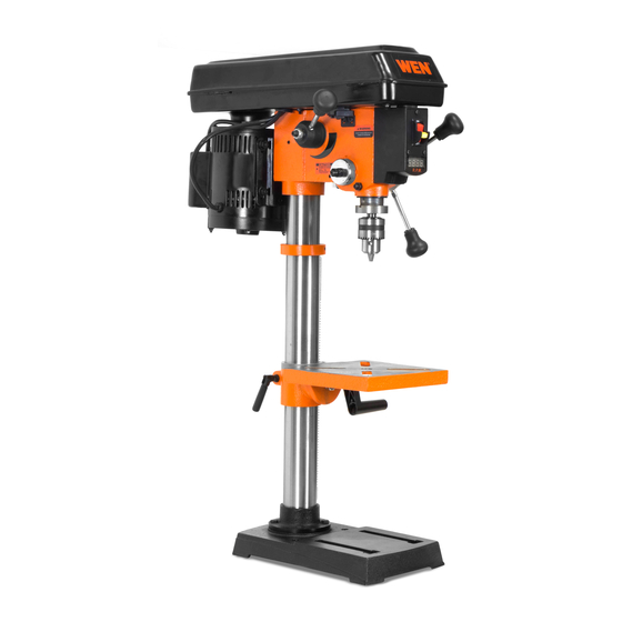
10" VARIABLE SPEED
IMPORTANT:
NEED HELP? CONTACT US!
Have product questions? Need technical support?
Please feel free to contact us at:
800-232-1195
techsupport@wenproducts.com
WENPRODUCTS.COM
MODEL 4212
DRILL PRESS
(M-F 8am-5pm CST)
226002
Advertisement
Table of Contents

Related Manuals for Wen 4212


Summary of Contents for Wen 4212
- Page 1 226002 IMPORTANT: Your new tool has been engineered and manufactured to WEN’s highest standards for dependability, ease of operation, and operator safety. When properly cared for, this product will supply you years of rugged, trouble-free performance. Pay close attention to the rules for safe operation, warnings, and cautions.
-
Page 2: Table Of Contents
Assembly & Adjustments .............. 10 Operation ..................18 Maintenance .................. 21 Troubleshooting Guide ..............22 Exploded View & Parts List ............24 Warranty Statement ............... 27 SPECIFICATIONS Model Number 4212 Motor 120V, 60 Hz, 5A Speed 530-3100 RPM (no load) Chuck Capacity 1/2" Stroke 2"... -
Page 3: Introduction
INTRODUCTION Thanks for purchasing the WEN drill press. We know you are excited to put your tool to work, but first, please take a moment to read through the manual. Safe operation of this tool requires that you read and understand this operator’s manual and all the labels affixed to the tool. This manual provides information regarding potential safety concerns, as well as helpful assembly and operating instructions for your tool. -
Page 4: General Safety Rules
GENERAL SAFETY RULES Safety is a combination of common sense, staying alert, and knowing how your item works. SAVE THESE SAFETY INSTRUCTIONS. WARNING: Read and understand all warnings, cautions and operating instructions before using this tool. Failure to follow all instructions listed below may result in personal injury and tool damage. - Page 5 GENERAL SAFETY RULES 4. Prevent unintentional starting. Ensure the switch is in the off-position before connecting to power source and/or battery pack, picking up or carrying the tool. Carrying power tools with your finger on the switch or energizing power tools that have the switch on invites accidents. 5.
-
Page 6: Specific Safety Rules For The Drill Press
SPECIFIC RULES FOR THE DRILL PRESS WARNING: Do not let comfort or familiarity with the product replace strict adherence to product safety rules. Failure to follow the safety instructions may result in serious personal injury. 1. TOOL PURPOSE. This drill press is designed to drill through metal wood, plastic, and tiles. Drilling through other materials could result in fire, injury, or damage to the workpiece. - Page 7 SPECIFIC RULES FOR THE DRILL PRESS 12. DRILLING THE WORKPIECE. • Allow spindle to reach full speed before drilling the workpiece. • Never start the machine with the drill bit pressed against the workpiece. • Adjust the table or depth stop to avoid drilling into the table. •...
-
Page 8: Electrical Information
ELECTRICAL INFORMATION GROUNDING INSTRUCTIONS IN THE EVENT OF A MALFUNCTION OR BREAKDOWN, grounding provides the path of least resistance for an electric current and reduces the risk of electric shock. This tool is equipped with an electric cord that has an equipment grounding conductor and a grounding plug. -
Page 9: Know Your Drill Press
KNOW YOUR DRILL PRESS TOOL PURPOSE Drill presses are mainly used to drill clean, precise cylindrical holes into workpieces or enlarge existing holes. You may also find other uses for your drill press such as reaming, countersinking, counterboring, tapping, etc. Refer to the diagram below and on page 10 to become familiarized with the parts and controls of your drill press. -
Page 10: Assembly & Adjustments
ASSEMBLY & ADJUSTMENTS UNPACKING With the help of a friend or trustworthy foe, carefully remove the drill press from the packaging. Make sure to take out all contents and accessories. Do not discard the packaging until the drill press is completely assembled. - Page 11 ASSEMBLY & ADJUSTMENTS WARNING: Do not plug in or turn on the tool until it is fully assembled according on the instructions. Failure to follow the safety instructions may result in serious personal injury. ATTACHING COLUMN TO BASE (FIG. 3) 1.
- Page 12 ASSEMBLY & ADJUSTMENTS DRILL PRESS HEAD TO COLUMN (FIG. 7) CAUTION: The drill press head is heavy. To avoid injury, two people should lift it into position. 1. Carefully lift the drill press head assembly (Fig. 7 - 1) and position it over the column (Fig.
- Page 13 ASSEMBLY & ADJUSTMENTS INSTALL THE CHUCK (FIG. 11) 1. Inspect and clean the taper hole in the chuck and the spindle. Remove all grease, coatings, and particles from the chuck and chuck arbor surfaces with a clean cloth. 2. Open the chuck jaws by manually turning the chuck barrel clockwise.
- Page 14 ASSEMBLY & ADJUSTMENTS ASSEMBLY & ADJUSTMENTS TILT THE TABLE (FIG. 13) 1. Loosen the bevel lock bolt (under table) with a suitable socket or wrench (not included). 2. Tilt the table to the desired angle, using the bevel scale (1) as a basic guide.
- Page 15 ASSEMBLY & ADJUSTMENTS ASSEMBLY & ADJUSTMENTS SQUARING THE TABLE TO THE DRILL BIT (FIG. 14) 1. Insert a 3" drill bit (Fig. 14-1) into the chuck (Fig. 14-2) and tighten. 2. Raise and lock the table (Fig. 14 - 3) about 1" from the end of the drill bit.
- Page 16 ASSEMBLY & ADJUSTMENTS ASSEMBLY & ADJUSTMENTS SPINDLE RETURN SPRING (FIG. 16A) The spindle is equipped with an auto-return mechanism. The main components are a spring and a notched housing. The spring was properly adjusted at the factory and should not be readjusted unless absolutely necessary.
- Page 17 ASSEMBLY & ADJUSTMENTS ASSEMBLY & ADJUSTMENTS DRILL PRESS ON/OFF SWITCH (FIG. 17) 1. To turn the drill press ON, insert the yellow safety key (Fig. 17-1) into the switch housing (Fig. 17 - 2). As a safety feature, the switch cannot be turned ON without the safety key. 2.
- Page 18 OPERATION ASSEMBLY & ADJUSTMENTS LASER LINE ON/OFF SWITCHES (FIG. 18) The laser switch (Fig. 18 - 1) is located on the left hand side of the drill press. 1. Pull the tab located below the laser switch and lift up the laser switch cover (Fig.
- Page 19 OPERATION ASSEMBLY & ADJUSTMENTS ADJUST THE DRILLING DEPTH (FIG. 19) 1. Loosen the depth scale knob and turn the depth scale ring to the desired depth. 2. Lock the scale ring in place by tightening the depth knob. This will stop the bit once it reaches a certain depth. Fig.
-
Page 20: Operation
OPERATION ASSEMBLY & ADJUSTMENTS FEEDING THE DRILL BIT • Pull down on the feed handles with only enough force to allow the drill bit to cut. • Feeding too rapidly might stall motor, cause the belt to slip, damage the workpiece, or break the drill bit. •... -
Page 21: Maintenance
WARNING: Any attempt to repair or replace electrical parts on this tool may be hazardous. Servicing of the tool must be performed by a qualified technician. When servicing, use only identical WEN replacement parts. Use of other parts may be hazardous or induce product failure. ROUTINE INSPECTION Before each use, inspect the general condition of the tool. -
Page 22: Troubleshooting Guide
TROUBLESHOOTING ASSEMBLY & ADJUSTMENTS WARNING: Stop using the tool immediately if any of the following problems occur. Repairs and replacements should only be performed by an authorized technician. For any questions, please contact our customer service at (800) 232-1195, M-F 8-5 CST or email us at techsupport@wenproducts.com. - Page 23 TROUBLESHOOTING ASSEMBLY & ADJUSTMENTS WARNING: Stop using the tool immediately if any of the following problems occur. Repairs and replacements should only be performed by an authorized technician. For any questions, please contact our customer service at (800) 232-1195, M-F 8-5 CST or email us at techsupport@wenproducts.com.
-
Page 24: Exploded View & Parts List
EXPLODED VIEW & PARTS LIST ASSEMBLY & ADJUSTMENTS... - Page 25 EXPLODED VIEW & PARTS LIST ASSEMBLY & ADJUSTMENTS Part No. Description Part No. Description 4212B-001 Retaining Plate 4212B-037 Battery Housing Cover 4212B-002 Set Screw, M8x12 4212B-038 Battery Housing 4212B-003 4212B-039 Handle Seat 4212B-004 Ball Bearing, 6907Z 4212B-040 Spring Pin, 5-15 4212B-005 Elastic Ring 4212B-041...
- Page 26 EXPLODED VIEW & PARTS LIST ASSEMBLY & ADJUSTMENTS Part No. Description Part No. Description 4212B-073 Table Lock Handle 4212B-092 Hex Nut, M10 4212B-074 Table 4212B-093 Washer 4212B-075 Hex Bolt, M12x25 4212B-094 Head 4212B-076 Rack 4212B-095 Flat Washer, M8 4212B-077 Column 4212B-096 Motor Plate 4212B-078...
-
Page 27: Warranty Statement
GREAT LAKES TECHNOLOGIES, LLC (“Seller”) warrants to the original purchaser only, that all WEN consumer power tools will be free from defects in material or workmanship for a period of two (2) years from date of purchase. Ninety days for all WEN products if the tool is used for professional or commercial use. - Page 28 THANKS FOR REMEMBERING...
Need help?
Do you have a question about the 4212 and is the answer not in the manual?
Questions and answers