Wen 4208 Operator's Manual
Hide thumbs
Also See for 4208:
- Instruction manual (24 pages) ,
- Instruction manual (24 pages) ,
- User manual
Table of Contents
Advertisement
Advertisement
Table of Contents

Related Manuals for Wen 4208


Summary of Contents for Wen 4208
-
Page 3: Table Of Contents
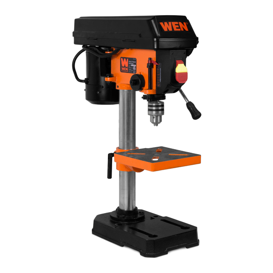
Operation………………………………………………………………... Maintenance…………………………………………………………….. Exploded view…………………………………………………………… 20 Parts list………………………………………………………………… Warranty………………………………………………………………… TECHNICAL DATA 8" Drill Press Model# 4208 Motor: 120 V, 60 Hz, 2.3 A, 1/3HP Horsepower: 1/3 HP (single phase) Drilling capacity: 2" Drill Depth / Spindle Travel: 2"... -
Page 4: General Safety Rules
GENERAL SAFETY RULES Safety is a combination of common sense, staying alert, and knowing how your drill press works. SAVE THESE SAFETY INSTRUCTIONS. WARNING: To avoid mistakes that could cause serious injury, do not plug in the drill press until the following steps have been read and understood. 1. - Page 5 GENERAL SAFETY RULES (CONTINUED) 13. NEVER LEAVE A RUNNING TOOL UNATTENDED. Turn the power switch to OFF. Do not leave the tool until it has come to a complete stop. 14. NEVER STAND ON A TOOL. Serious injury could result if the tool tips or is accidentally hit. DO NOT store anything above or near the tool.
-
Page 6: Specific Safety Rules For Drill Press
SPECIFIC SAFETY RULES FOR DRILL PRESS WARNING: Do not operate your drill press until it is completely assembled and installed according to the instructions. 1. Never turn on the drill press before clearing the table of all objects (tools, scraps, etc.). 2. -
Page 7: Electrical Information
ELECTRICAL INFORMATION Grounding instructions IN THE EVENT OF A MALFUNCTION OR BREAKDOWN, grounding provides the path of least resistance for electric current and reduces the risk of electric shock. This tool is equipped with an electric cord that has an equipment grounding conductor and a grounding plug. The plug MUST be plugged into a matching outlet that is properly installed and grounded in accordance with ALL local codes and ordinances. - Page 8 ELECTRICAL INFORMATION (CONTINUED) Guidelines for using extension cords Make sure your extension cord is in good condition. When using an extension cord, be sure to use one heavy enough to carry the current your product will draw. An undersized cord will cause a drop in line voltage resulting in loss of power and overheating.
-
Page 9: Assembly And Adjustments
ASSEMBLY AND ADJUSTMENTS Unpacking (Fig. 2) Unpack the drill press and all its parts, and compare against the list below. Do not discard the carton or any packaging until the drill press is completely assembled. To protect the drill press from moisture, a protective coating has been applied to the machined surfaces. Remove this coating with a soft cloth moistened with kerosene or WD-40®. - Page 10 ASSEMBLY AND ADJUSTMENTS (CONTINUED) Tools needed for assembly Adjustable wrench Hammer and block of wood Screwdriver Base to column (Fig. 3) 1. Set the base (1) on the floor. 2. Place the column tube (2) on the base (1), align the column support holes with the base holes.
- Page 11 ASSEMBLY AND ADJUSTMENTS (CONTINUED) Feed handles 1. Thread the three feed handle rods into the holes on the feed hub. 2. Hand tighten. Note: One or two of the feed handles may be removed if an unusually-shaped workpiece interferes with handle rotation.
- Page 12 ASSEMBLY AND ADJUSTMENTS (CONTINUED) Remove the chuck at a later time (Fig. 8) 1. Turn the feed handles to lower the chuck (2) to the lowest position. 2. Place a ball joint separator tool (not included, not shown) above the chuck (3) and tap it lightly with a hammer (4) to cause the chuck to drop from the spindle.
- Page 13 ASSEMBLY AND ADJUSTMENTS (CONTINUED) Adjustments Spindle speeds (Fig. 10) This drill press offers 5 spindle speeds from 620 to 3100 RPM. The highest speed is obtained when the belt is positioned on the largest motor pulley step and the smallest spindle pulley stop. WARNING: Disconnect the drill press from the power source before making any speed adjustments.
- Page 14 ASSEMBLY AND ADJUSTMENTS (CONTINUED) Tilt the table (Fig. 12) The table can be tilted from 0 to 45° to the left and right. 1. Loosen the bevel lock bolt (1) with a wrench. 2. Tilt the table (2) to the desired angle, using the bevel scale (3) as a basic guide.
- Page 15 ASSEMBLY AND ADJUSTMENTS (CONTINUED) 5. Loosen and remove the outer jam nut (3). 6. Loosen, BUT DO NOT REMOVE, the inner nut (4). 7. Pull out, BUT DO NOT REMOVE, the housing (5) from the raised lug (6) on the drill press head. 8.
-
Page 16: Operation
OPERATION Position the table and workpiece (Fig. 16) Always place a piece of backup material (1) (wood, plywood, etc.) on the table underneath the workpiece (2). This will prevent splintering on the underside of the workpiece as the drill bit breaks through. To keep the material from spinning out of control, it must contact the left side of the column as illustrated, or be clamped to the table. - Page 17 OPERATION (CONTINUED) Drilling to a specific depth (Fig. 17) 1. Mark the desired depth of the hole on the side of the workpiece (1). 2. With the switch off, bring the drill bit (2) down until the tip is even with the mark. 3.
- Page 18 OPERATION (CONTINUED) Drilling wood Brad point bits are preferred. Metal piercing twist bits may be used on wood. Do not use auger bits. They turn so rapidly that they lift the workpiece off the table and whirl it around.
-
Page 19: Maintenance
MAINTENANCE Blow out or vacuum sawdust or metal chips that accumulate in and on the motor, pulley housing, table, and work surface. Apply a light coat of paste wax to the column and table to help keep these surfaces clean and rust-free. The ball bearings in the spindle and the V-belt pulley assembly are greased and permanently sealed. -
Page 20: Exploded View
EXPLODED VIEW... -
Page 21: Parts List
PARTS LIST Part # Stock # Description Part # Stock # Description 4208-001 BELT 4208-033 SCREW ST4.2X9.5 4208-002 SET SCREW M8X10 4208-034 ON/OFF SWITCH 4208-003 SPINDLE PULLEY 4208-035 RETAINING RING 11 4208-004 MOTOR PULLEY 4208-036 BEARING 4208-005 WASHER 4208-037 WASHER... -
Page 22: Warranty
(1) year from date of purchase. Ninety (90) days for all WEN Products, if the tool is used for professional or commercial use.
Need help?
Do you have a question about the 4208 and is the answer not in the manual?
Questions and answers