CIRCLE FITNESS R8 Owner's Manual
Hide thumbs
Also See for R8:
- Owner's manual (46 pages) ,
- Service manual (20 pages) ,
- Service manual (9 pages)
Table of Contents
Advertisement
Quick Links
Advertisement
Table of Contents

Subscribe to Our Youtube Channel
Related Manuals for CIRCLE FITNESS R8


Summary of Contents for CIRCLE FITNESS R8
-
Page 3: Table Of Contents
R8 – Owner’s Manual Version: 20190201_V001 TABLE OF CONTENTS INTRODUCTION ________________________________________________________________ 3 1. SAFETY _____________________________________________________________________ 4 1. 1 Important Safety Notes _________________________________________________________________ 4 2. ASSEMBLY __________________________________________________________________ 6 2.1 Specifications __________________________________________________________________________ 6 2.2 Machine Overview ______________________________________________________________________ 7 2.3 Location and Transportation ____________________________________________________________ 8 2.4 Unpacking _____________________________________________________________________________ 9... -
Page 4: Introduction
R8 – Owner’s Manual INTRODUCTION Dear Customer, Thank you for purchasing this product. This Owner’s Manual will guide you through the setup procedures and outline the key features. Please keep it handy for future reference. This product has been designed and manufactured for studio use, and even though we go to great efforts to ensure the quality of each product, occasional errors, and/or omissions do occur. -
Page 5: Safety
R8 – Owner’s Manual 1. SAFETY 1. 1 Important Safety Notes IMPORTANT: Please read all instructions and warnings before assembly and operation. To assure the correct use of the product, basic safety measures should always be followed including the warnings and cautions listed in this Owner’s Manual. - Page 6 R8 – Owner’s Manual 1. 1 Important Safety Notes (Continued) WARNING: Make sure all bolts and nuts are securely tightened before operating this equipment. Periodic maintenance is required on all exercise equipment to keep it in good condition. WARNING: Incorrect/ excessive training can cause health injuries. Stop using the equipment when feeling uncomfortable.
-
Page 7: Assembly
R8 – Owner’s Manual 2. ASSEMBLY Specifications Model : R8 Technical Specifications Resistance Level 25 Levels Maximum User Weight 150 kg (330 Ibs) Features Display Type 6 LEDs + 8x32 Dot-Matrix 10° Recline Adjustable Heart Rate Receiver Standard Chest Belt... -
Page 8: Machine Overview
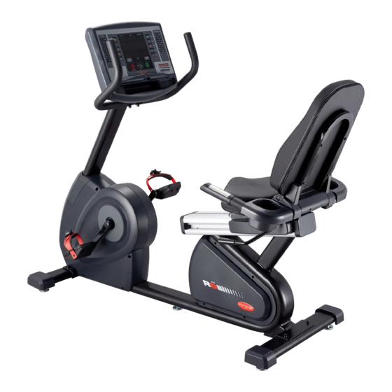
R8 – Owner’s Manual 2.2 Machine Overview Back Rest Console Set Lower Handlebar Upper Handlebar Bottle Holder Console Upright Tube Seat Lock Handle Seat Rail Rear Stabilizer Tube Pedal with Strap Main Frame Front Stabilizer Tube Page... -
Page 9: Location And Transportation
R8 – Owner’s Manual 2.3 Location and Transportation Location Place the equipment on a level surface. Do NOT place it in any area that will block any vents or air openings. This equipment should not be located in a garage, covered patio, near water or outdoors. -
Page 10: Unpacking
R8 – Owner’s Manual 2.4 Unpacking 1. Carefully remove all staples from the carton. 2. Open the Carton 1 and remove the upper cardboard piece. Lift the cover upward and set it aside. (Fig 2.4-1) Carton 1 Fig 2.4-1 3. Open the Carton 2 and remove the packing materials to take out the Console. (Fig 2.4-2) Carton 2 Fig 2.4-2... - Page 11 R8 – Owner’s Manual 2.4 Unpacking (Continued) Please verify that you have parts as per the list shown below: NOTE: Make sure that Serial Number on Carton 1 matches that on Carton 2. Parts: Main Frame (Carton1/ Carton 2) Front Stabilizer...
- Page 12 R8 – Owner’s Manual 2.4.1 Hardware Kit Please verify the hardware kit list as shown below: STEP 8 STEP 11 (1) M8 x 65 mm Screws (2 PCS) (1) M6 x 45 mm Screws (4 PCS) (2) M6 S Washers (4 PCS)
- Page 13 R8 – Owner’s Manual 2.4.2 Tools Please verify the tools list as shown below: M10/M10 Combination Wrench M15/M15 Combination Wrench Allen Wrench (3mm) Allen Wrench (4mm) Allen Wrench (5mm) Allen Wrench (6mm) Allen Wrench (8mm) Owner’s Manual Page...
-
Page 14: Assembly Procedure
R8 – Owner’s Manual 2.5 Assembly Procedure STEP 1: Attach the Front and Rear Stabilizer Tubes to the Main Frame. NOTE: You will need the help of another person while performing this procedure. 1) Unscrew the (2) Pre-Locked Screws And... - Page 15 R8 – Owner’s Manual STEP 2: Attach the Pedal Set to the Crank Arm. 1) Attach the Right Pedal #1 to the right crank arm, tightening it clockwise with the M15/M15 provided Combination Wrench. Right Pedal #1 (Fig 2.5-2) 2) Attach the Left Pedal #2 to the left crank...
- Page 16 R8 – Owner’s Manual STEP 3: Unscrew the Pre-Locked items. (Cont’d) 2) Unscrew the (2) Pre-Locked Screws #3 & #4 on Supporting Column #5 with the provided 6mm Allen wrench. (Fig 2.5-4B) Supporting Column #5 Pre-Locked Screws (Shorter) & Washers #3 Pre-Locked Screws (longer) &...
- Page 17 R8 – Owner’s Manual STEP 4: Routing the Console Wire through the Console Upright Tube. 1) Slide the Upright Tube Cover #1 to the Console Console Upright Tube #2. (Fig2.5-4A) Upright Tube #2 Slide 2) Thread the Lower Console Wire #3 on the...
- Page 18 R8 – Owner’s Manual STEP 5: Secured the Console Upright Tube on the Main Frame. 1) Tighten (1) M8 x 70mm Screw, (1) M8 Washer and (1) M8 Flat Washer (Fig 2.5-5A, ○ ) with 6 mm Allen Wrench. ○...
- Page 19 R8 – Owner’s Manual STEP 6: Align and Reinstall the Upright Tube Cover. Reinstall the Upright Tube Cover#1 by securing the (2) M4 x 15mm Screws #2 M4 x 15mm (Pre-locked screws on STEP 3) with the Screws #2 provided 5mm Allen Wrench. (Fig 2.5-6) Upright Tube Cover#1 Fig 2.5-6...
- Page 20 R8 – Owner’s Manual STEP 7: Attach the Console Set to the Console Upright Tube. 1) Unscrew the (4) Pre-Locked Screws #1 on Console Set #2 the Console Set #2. (Fig 2.5-7A) 2) Connect the Connectors (○ , ○ , ○...
- Page 21 R8 – Owner’s Manual STEP 8: Attach the Upper Handlebar to the Console Set. 1) Attach the Upper Handlebar #1 to the Console Upright Tube #2 using (2) M8 x 65mm Screws, (2) M8 S Washers and (2) M8 Curve Washers (Fig 2.5-8, ○...
- Page 22 R8 – Owner’s Manual STEP 9: Attach the Backrest to the Main Frame. 1) Unscrew the (6) Pre-Locked Screws & S Pre-Locked Screws & Washers #1 on the Rack Set #2. (Fig S Washers #1 2.5-9A) Unscrew Rack Set #2 Fig 2.5-9A...
- Page 23 R8 – Owner’s Manual STEP 10: Attach the Lower Handlebar to the Backrest Frame. 1) Unscrew (4) the pre-locked screw and (4) S washers on the lower handlebar. (Fig Backrest 2.5-10A) Lower Handlebar #1 Frame#2 Unscrew Hand Pulse Fig 2.5-10A...
- Page 24 R8 – Owner’s Manual STEP 11: Attach the Seat Pad to the Backrest Frame. 1) Attach the the Seat Pad #1 to the Backrest Frame #2 using (4) M6 x 45 mm Screws Backrest Frame #2 #3 and (4) M6 S Washers #4 with the Seat Pad #1 provided 6mm Allen Wrench.
- Page 25 R8 – Owner’s Manual STEP 12: Attach the Recline Lever Set to the Left Side of the Track. 1) Screw the Handle #1 into Recline Lever #2. M6 S Washer #6 M6 Nut #5 2) Attach the Recline Lever Set #3 to the left...
- Page 26 R8 – Owner’s Manual STEP 13: Attach the Seat Frame Cover to the Lower Handlebar. Attach the Seat Frame Cover #1 to the Lower Seat Frame Cover #1 Handlebar #2 using (2) M4 x 12 mm Screws #3 with the provided 5mm Allen Wrench. (Fig 2.5-13)
- Page 27 R8 – Owner’s Manual STEP 14: Attach the Backrest to the Backrest Frame. Attach the Backrest #1 to the Backrest Backrest #1 Frame #2 using (4) M6 x 45 mm Screws #3 Backrest Frame #2 and (4) M6 S Washers #4 with the provided 4mm Allen Wrench.
- Page 28 R8 – Owner’s Manual STEP 16: Attach the Rear Backrest Cover to the Lower Handlebar. 1) Unscrew the (2) pre-locked screws. (Fig Rear Backrest 2.5-16, ○ Unscrew Cover #1 M4 x 10 mm Screws #3 2) Attach the Rear Backrest Cover #1 to the ○...
- Page 29 R8 – Owner’s Manual STEP 18: Attach the Seat Lock lever Set to the Track. 1) Screw the Handle #1 into Seat Lock lever Seat Lock lever #2 #2. (Fig 2.5-18, ○ ○ Handle #1 2) Unscrew the (2) pre-locked screws on the ○...
- Page 30 R8 – Owner’s Manual STEP 19: Attach the Adjust Pad to the Main Frame. NOTE: You will need the help of another person while performing this procedure. Lift up the Main Frame #1 and screw the Adjust Pad #2 in to the bottom of the Main Frame #1.
-
Page 31: Adjustments
R8 – Owner’s Manual 2.6 Adjustments Adjusting the Pedal Straps Unlock the buckle The pedal straps keep the user’s shoes firmly to adjust the strap. on the pedals during a workout. The straps should fit comfortably, but they also should be tight enough to prevent shoes from slipping at any point in the pedaling rotation. -
Page 32: Engineering Settings
R8 – Owner’s Manual 2.7 Engineering Settings Press and hold the (CLEAR/RESET) button then press (LEVEL UP) button for 3 seconds to enter the engineering mode while in idle mode. Software Version: Machine Type Selection: Message window shows【VER】, time Message Window shows【SET TYPE】, window shows software version, press Distance &... -
Page 33: Test Operation
R8 – Owner’s Manual 2.8 Test Operation Follow the instructions below to test the full resistance range: 1). Hold the handlebars to steady yourself while stepping into the pedals. Begin pedaling. 2). Verify the LED display will illuminate. 3). Run through the full resistance range. -
Page 34: Operation
R8 – Owner’s Manual 3. OPERATION 3.1 Heart Rate System WARNING: The heart rate reading is intended only as an exercise aid and not for medical purposes. Heart rate monitoring systems may be inaccurate. Various factors may affect the accuracy of heart rate readings. Over exercise may result in serious injury or death. If you feel faint, please stop all exercise immediately. -
Page 35: Body Position
R8 – Owner’s Manual 3.2 Body Position Your handlebars should be set to a position in which you can comfortably reach them with slightly bent arms. (Fig 3.2-1) Fig 3.2-1 3.3 Changing Resistance Levels Press the Resistance level + (... -
Page 36: Console Overview
R8 – Owner’s Manual 4. CONSOLE OVERVIEW 4.1 Identifying the Parts of the Console The following figure provides information about the console keys. Table 4-1, Parts of the Console - Display Functions Number Part Name Descriptions Distance Displays total distance KM/Mi. - Page 37 R8 – Owner’s Manual Table 4-2, Parts of the Console - Keypad Function Number Part Name Descriptions Number (Key) Pad Set value. Adjusts level to a predetermined value. Quick Resistance There are 10 level quick keys. Preset programs The following 7 preset programs can be selected directly: ‧...
-
Page 38: Program Profiles And Operation
R8 – Owner’s Manual 4.2 Program Profiles and Operation Rolling 4.2.1 Preset Program: Rolling (P1) Maintains weight by gradually raising and lowering the resistance level to gradually raise and lower your heart rate. Segment Level 1 Level 2 Level 3... - Page 39 R8 – Owner’s Manual 4.2.3 Preset Program: Fat Burn (P3) Fat Burn Promotes weight loss by raising and lowering resistance level while keeping you in your fat burning zone. Segment Level 1 Level 2 Level 3 Level 4 Level 5...
- Page 40 R8 – Owner’s Manual 4.2.5 Preset Program: Strength (P5) Strength Helps you to gradually increase your muscle strength with a preset workout program. Segment LEVEL 1 LEVEL 2 LEVEL 3 LEVEL 4 LEVEL 5 Strength Segment LEVEL 1 LEVEL 2...
- Page 41 R8 – Owner’s Manual 4.2.7 Preset Program: Random (P7) Specially designed chart based program that will simulate resistance being changed randomly. 4.2.8 Preset Programs Operation Procedures: Rolling Valley Fat Burn Random Ramp Strength Interval Press the preset program, Press one of the preset Random button.
- Page 42 R8 – Owner’s Manual 4.2.9 Target Allow you to set the Workout Time, Distance and Calories. Target program operation procedure: Set “Bodyweight” then Press Target press ENTER button. button. Set “Time” then press ENTER button. Set “Distance” then press ENTER button.
- Page 43 R8 – Owner’s Manual 4.2.10 Fitness Test Test your current level of physical condition. Fitness Test Program operation procedure: Press Fitness Test Set “Bodyweight” then Set “AGE” then press press ENTER button. ENTER button. button. Press GO button to start workout.
- Page 44 R8 – Owner’s Manual 4.2.11 H.R.C (Heart Rate Control) The heart rate program allows you to set a target heart rate for your workout. To use this program a chest belt (Optional) must be worn. This program will compare the Actual Heart Rate and the Preset Heart Rate every 30 seconds and will adjust the resistance level until the Actual Heart Rate reaches a point within +5 or –...
- Page 45 R8 – Owner’s Manual H.R.C program operation procedure: Press H.R.C button. Message Window shows ”THR” (Target Heart Rate), press ▲ or ▼ button to select HRC 60%,HRC 75% or HRC 85%. THR Mode HRC Mode SET “TARGET HEART Select HRC 60% or HRC RATE”...
-
Page 46: Engineering Mode
R8 – Owner’s Manual 5. ENGINEERING MODE 5.1 ENGINEERING MODE 1: Settings While in idle mode, press and hold the (CLEAR/RESET) button then press the (LEVEL UP) button for 3 seconds to enter the setting mode. Software Version: Machine Type Selection: Message window shows【VER】, time... -
Page 47: Engineering Mode 2: Test Mode
R8 – Owner’s Manual 5.2 ENGINEERING MODE 2: Test Mode Press and hold the (CLEAR/RESET) button then press (GO) button for 3 seconds to enter the Engineering Mode 2 while in idle mode. Software Version: Message Window shows 【VER】 , time window shows software version, press ENTER to start Test Mode. -
Page 48: Maintenance
R8 – Owner’s Manual 6. MAINTENANCE 6.1 Preventive Maintenance Tips The Safety of the equipment can be maintained only if it is examined regularly for damage or wear. If maintenance is required, keep the equipment out of use until defective parts are repaired or replaced. -
Page 49: Troubleshooting
R8 – Owner’s Manual 6.3 Troubleshooting Item Error Message Descriptions CAUSE: Communication timeout. This error message pops up if console and generator lose communication for over 90 seconds. COMMUNICATION FAIL SOLUTION: - Check that the console and generator are connected properly. - Page 50 R8 – Owner’s Manual 6.3 Troubleshooting (Continued) Item Error Message Descriptions CAUSE: The generator output voltage is overloaded. SOLUTION: MV VOLT OVERLOAD - Stop peddling and wait for the power to shut down. - Peddle to power up the console. If the error message pops up again, replace the generator.
-
Page 51: Customer Service
R8 – Owner’s Manual 7. CUSTOMER SERVICE 7.1 Warranty Claim Process Please apply online for submission of warranty claims. For submission online of warranty claims please go to http://goo.gl/forms/OplmbWO9kXHJuDYc2. To submit warranty claims, you will be asked to provide information in your submission, and also to upload your pictures/video clips. - Page 52 R8 – Owner’s Manual Page...
Need help?
Do you have a question about the R8 and is the answer not in the manual?
Questions and answers