Table of Contents
Advertisement
Quick Links
Advertisement
Table of Contents

Related Manuals for HAMPTON BAY SEAPORT AL634-WH


Summary of Contents for HAMPTON BAY SEAPORT AL634-WH
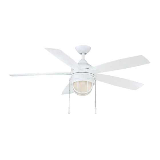
- Page 1 Item # xxx-xxx Model # AL634-WH USE AND CARE GUIDE SEAPORT 52 INCH CEILING FAN Questions, problems, missing parts? Before returning to the store call Hampton Bay Customer Service 8 a.m. - 6 p.m., EST, Monday-Friday 1-877-527-0313 HAMPTONBAY.COM THANK YOU...
-
Page 2: Table Of Contents
Table of Contents Table of Contents ............Operation ..............Pull Chain Operating Instructions .......... Safety Information ............Reverse Switch Operating Instructions ........Warranty ................. Care and Cleaning ............Pre-installation .............. Troubleshooting ............Specifications ................Tools Requires ................. Service Parts ............... Hardware Included .............. -
Page 3: Safety Information
Safety Information To reduce the risk of electric shock, insure electricity has WARNING: Use only with light kit marked "Suitable for Use been turned off at the circuit breaker or fuse box before in Wet Locations". beginning. All wiring must be in accordance with the National Electrical Code “ANSI/NFPA 70-1999”... -
Page 4: Warranty
The Hampton Bay warrants the fan motor to be free from defects in workmanship and material present at time of shipment from the factory for a period of lifetime after the date of purchase by the original purchaser. Hampton Bay also warrants that all other fan parts, excluding any glass or acrylic blades, to be free from defects in workmanship and material at the time of shipment from the factory for a period of one year after the date of purchase by the original purchaser. -
Page 5: Hardware Included
Pre-Installation (continued) HARDWARE INCLUDED HARDWARE INCLUDED NOTE: Hardware shown to actual size. Part Part Description Description Quantity Quantity Blade attachment hardware Electrical hardware Light kit hardware Balance kit Canopy mounting screws (preassembled) Clevis pin (preassembled) Cotter pin (preassembled) Collar set screws (preassembled) Blade arm hardware (preassembled) Mounting ring screws (preassembled) Light kit mounting screws (preassembled) -
Page 6: Package Contents
Pre-Installation (continued) PACKAGE CONTENTS PACKAGE CONTENTS Part Description Description Part Description Description Mounting bracket (Pre-installed in the canopy) 5 blades Canopy 5 blade arms Canopy bottom cover (Preassembled) Light kit mounting plate Hanger ball/downrod assembly Light kit Coupling cover Glass shades/decorative frame assembly Fan motor assembly... - Page 7 This page intentionally left blank. HAMPTONBAY.COM Please contact 1-877-527-0313 for further assistance.
-
Page 8: Installation
Installation MOUNTING OPTIONS MOUNTING OPTIONS WARNING: To reduce the risk of fire, electric shock, or NOTE: You may need a longer downrod to maintain proper personal injury, mount the fan to outlet box (OO) marked blade clearance when installing on a steep, sloped ceiling. acceptable for fan support using the screws provided with the The maximum angle allowable is 18°... -
Page 9: Assembly
Assembly Preparing the canopy Preparing the motor □ □ Remove the canopy bottom cover (C) from the canopy Remove the clevis pin (FF), cotter pin (GG), and (B) by turning the canopy bottom cover (C) counter- loosen the 2 collar set screws (HH) from the motor clockwise. -
Page 10: Hanging The Fan
Assembly — Hanging the Fan Installing the mounting bracket to the electrical box WARNING: To reduce the risk of fire, electric shock or other personal injury. Mount fan only to an outlet box or supporting system marked acceptable for fan support and use the mounting screws provided with the outlet box. - Page 11 Assembly — Hanging the Fan (continued) Making the electrical connections WARNING: To avoid possible electrical shock, be sure electricity is turned off at the main fuse box before wiring. If you feel you do not have enough electrical wiring knowledge or experience, have your fan installed by a licensed electrician.
- Page 12 Assembly — Hanging the Fan (continued) Attaching the canopy bottom Installing the canopy cover □ Attach the canopy bottom cover (C) to the canopy WARNING: Make sure the tab on the mounting bracket (A) mounting screw heads by inserting the screw heads properly sits in the groove in the hanger ball (D) before into the key slots in the canopy bottom cover (C) and attaching the canopy (B) to the mounting bracket (A) by...
-
Page 13: Attaching The Fan Blades
Assembly — Attaching the Fan Blades Attaching the blades to the Fastening the blade blade arms assemblies to the motor □ □ Attach blades (G) to blade arms (H) using the 3 Fasten the blade assemblies to the fan motor screws with rubber washers provided with the blade assembly (F) by lining up the slots of the blade arms attachment hardware (AA). -
Page 14: Installing The Light Kit
Assembly — Installing the Light Kit Installing the light kit mounting Mounting the light kit to the plate light kit mounting plate □ Remove the 1 of 3 mounting ring screws (JJ) from the CAUTION: Before starting installation, disconnect the mounting ring and loosen the other 2 screws. - Page 15 Assembly — Installing the Light Kit (continued) Mounting the Glass Shade/ Installing the Light Bulbs Decorative Frame Assembly □ Raise the glass shade/decorative frame assembly (K) CAUTION: Before starting installation, disconnect the up against bottom of light kit (J), align the holes in power by turning off the circuit breaker or removing the fuse the rim of the decorative frame with the light kit (J) at fuse box.
-
Page 16: Operation
Operation PULL CHAIN OPERATING INSTRUCTIONS PULL CHAIN OPERATING INSTRUCTIONS Install two pull chains and fobs (MM) onto the pull chains located in the light kit (J). Turn on the power and check the operation of the fan. The pull chain controls the fan speed as follows: 1 pull - High, 2 pulls - Medium, 3 pulls - Low and 4 pulls - Off. -
Page 17: Care And Cleaning
Care and Cleaning Do Do Do not Do not □ □ Check the support connections, brackets, and blade Do not use water when cleaning. Water could damage the attachments twice a year. Make sure they are secure. motor, or the wood, or possibly cause an electrical shock. Because of the fan’s natural movement, some □... - Page 18 Troubleshooting (continued) Problem Solution Solution □ This unit is equipped with a wattage limiting device. Lamping in excess of 190 watts will disable your Lights shut off and will not ceiling fan's light kit. To reset your light kit you must turn the power off and relamp, keeping the come back on.
-
Page 19: Service Parts
Service Parts Part Part Description Description Part Part Description Mounting bracket (Pre-installed in the canopy) Electrical hardware Canopy Light kit hardware Canopy bottom cover (Pre-installed) Balance kit Hanger ball/downrod assembly Canopy mounting screws (preassembled) Coupling cover Clevis pin (preassembled) Fan motor assembly Cotter pin (preassembled) 5 blades Collar set screws (preassembled) - Page 20 Questions, problems, missing parts? Before returning to the store call Hampton Bay Customer Service 8 a.m. - 6 p.m., EST, Monday-Friday 1-877-527-0313 HAMPTONBAY.COM Retain this manual for future use. AL634000001-B...
Need help?
Do you have a question about the SEAPORT AL634-WH and is the answer not in the manual?
Questions and answers