Table of Contents
Advertisement
Quick Links
USE AND CARE GUIDE
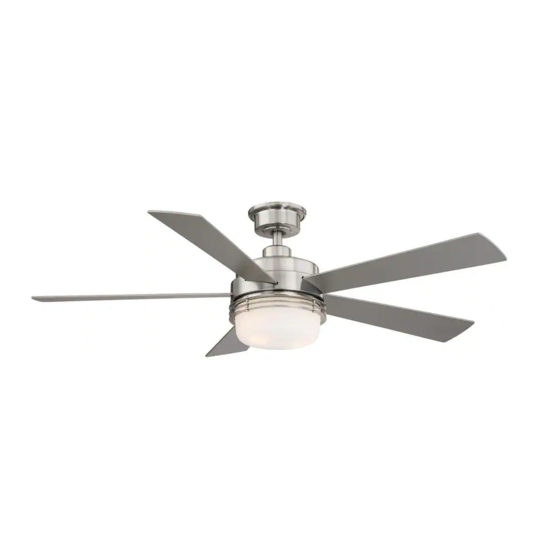
SUSSEX II 52 INCH CEILING FAN
Questions, problems, missing parts? Before returning to the store,
call Hampton Bay Customer Service
8 a.m. - 7 p.m., EST, Monday-Friday, 9 a.m. - 6 p.m., EST Saturday
1-855-HD-HAMPTON
HAMPTONBAY.COM
Visual instruction of how to install this fan:
Visit www.homedepot.com and enter either the Item or Model number to nd
this fan and click the link of visual instruction in the product overview section.
THANK YOU
Item #1005 228 025
Model #AL694LED-BN
Advertisement
Table of Contents

Related Manuals for HAMPTON BAY SUSSEX II AL694LED-BN


Summary of Contents for HAMPTON BAY SUSSEX II AL694LED-BN
- Page 1 USE AND CARE GUIDE SUSSEX II 52 INCH CEILING FAN Questions, problems, missing parts? Before returning to the store, call Hampton Bay Customer Service 8 a.m. - 7 p.m., EST, Monday-Friday, 9 a.m. - 6 p.m., EST Saturday 1-855-HD-HAMPTON HAMPTONBAY.COM Visual instruction of how to install this fan: Visit www.homedepot.com and enter either the Item or Model number to nd...
-
Page 2: Table Of Contents
Table of Contents Table of Contents ............Operation ..............Remote Control Operating Instructions ........Safety Information ............Reverse Switch Operating Instructions ........Warranty ................. Care and Cleaning ............Pre-installation .............. Troubleshooting ............Specifications ................Tools Required ................. Service Parts ..............Hardware Included .............. -
Page 3: Safety Information
Safety Information To reduce the risk of electric shock, ensure electricity has However, there is no guarantee that interference will not occur been turned off at the circuit breaker or fuse box before in a particular installation. If this equipment does cause harmful beginning. -
Page 4: Warranty
Warranty The manufacturer warrants the fan motor to be free from defects in workmanship and material present at time of shipment from the factory for a period of lifetime after the date of purchase by the original purchaser. The manufacturer warrants the light kit (excluding any glass), to be free from defects in workmanship and material at the time of shipment from the factory for a period of three years after the date of purchase by the original purchaser. -
Page 5: Hardware Included
Pre-Installation (continued) HARDWARE INCLUDED HARDWARE INCLUDED NOTE : Hardware not shown to actual size. Part Part Description Description Quantity Quantity Plastic wire nut Blade attachment screw and fiber washer Plastic wire nut 9.5 Watt LED medium base bulb 1.5V AAA battery HAMPTONBAY.COM Please contact 1-855-HD-HAMPTON for further assistance. -
Page 6: Package Contents
Pre-Installation (continued) PACKAGE CONTENTS PACKAGE CONTENTS Part Part Description Description Quantity Quantity Part Part Description Description Quantity Quantity Mounting bracket (preassembled) Blade Canopy ring (preassembled) Light kit mounting plate Canopy Light kit Hanger ball / downrod assembly Glass shade Coupling cover Receiver Fan motor assembly Remote control... -
Page 7: Installation
Installation MOUNTING OPTIONS MOUNTING OPTIONS NOTE: You may need a longer downrod to maintain proper WARNING: To reduce the risk of fire, electric shock, or blade clearance when installing on a steep, sloped ceiling. personal injury, mount the fan to an outlet box marked The maximum angle allowable is 18°... -
Page 8: Assembly
Assembly Preparing the canopy Preparing the motor □ □ Remove the cotter pin (GG) and clevis pin (HH). Loosen Remove the canopy ring (B) from the canopy (C). the two collar setscrews (II) from the motor collar. □ Remove the two non-slotted canopy mounting screws with lock washers (FF) from the canopy (C), and loosen the slotted canopy mounting screws with lock washers (FF) on the canopy (C). -
Page 9: Hanging The Fan
Assembly — Hanging the Fan Hanging the fan to the mounting Installing the mounting bracket bracket to the electrical box WARNING: To reduce the risk of fire, electric shock or WARNING: The tab in the ring must rest in the groove of other personal injury, mount the fan only to an outlet box or the hanger ball / downrod assembly (D). - Page 10 Assembly — Hanging the Fan (continued) Preparing the receiver and remote control NOTE: The frequencies on your receiver and remote control have been preset at the factory. Before installing the receiver, make sure the dip switches on the receiver and remote control are set to the same frequency.
- Page 11 Assembly — Hanging the Fan (continued) Making the electrical connections Ground conductor Black White WARNING: Check to see that all connections are tight, including ground, and that no bare wire is visible at the wire nuts, except for the ground wire. CAUTION: Do not use with a wall light dimmer switch.
- Page 12 Assembly — Hanging the Fan (continued) Installing the canopy Outlet Box WARNING: Make sure the tab on the mounting bracket (A) properly sits in the groove in the hanger ball / downrod assembly (D) before attaching the canopy (C) to the mounting bracket (A) by turning the canopy (C) until it drops into place.
-
Page 13: Attaching The Fan Blades
Assembly — Attaching the Fan Blades Attaching the fan blades WARNING: To reduce the risk of personal injury, do not bend the blades (G) while installing, balancing the blades (G), or cleaning the fan. WARNING: Do not insert foreign objects between rotating fan blades (G). -
Page 14: Installing The Light Kit
Assembly — Installing the Light Kit Attaching the light kit mounting Attaching the light kit plate to the mounting ring □ Remove one of the three light kit mounting plate CAUTION: Before starting installation, disconnect the screws (JJ) from the mounting ring (KK) and loosen power by turning off the circuit breaker or removing the fuse the other two screws. - Page 15 Assembly — Installing the Light Kit (continued) Installing the light bulbs and glass shade CAUTION: Before starting installation, disconnect the power by turning off the circuit breaker or removing the fuse at the fuse box. Turning power off using the fan switch is not sufficient to prevent electric shock.
-
Page 16: Operation
Operation REMOTE CONTROL OPERATING INSTRUCTIONS REMOTE CONTROL OPERATING INSTRUCTIONS - Press and release the button to turn the fan on or off. - Press and release 1 time - turns the fan on high speed. - Press and release 2 times - turns the fan on medium speed. - Press and release 3 times - turns the fan on low speed. -
Page 17: Reverse Switch Operating Instructions
Operation (continued) REVERSE SWITCH OPERATING INSTRUCTIONS REVERSE SWITCH OPERATING INSTRUCTIONS The reverse switch is located on the surface of the motor housing. Slide the switch to the left for warm weather operation. Slide the switch to the right for cool weather operation. Reverse switch NOTE: Wait for the fan to stop before reversing the direction of the blade rotation. -
Page 18: Troubleshooting
Troubleshooting WARNING: Make sure the power is off at the electrical panel box before you attempt any repairs. Refer to step 7 “Making the electrical connections” on page 11. Problem Problem Solution Solution □ Check the main and branch circuit fuses or breakers. □... -
Page 19: Service Parts
Service Parts Part Part Description Description Part Part Description Description Mounting bracket (preassembled) Plastic wire nut Canopy ring (preassembled) Blade attachment screw and fiber washer Canopy Plastic wire nut Hanger ball / downrod assembly 9.5 Watt LED medium base bulb Coupling cover 1.5V AAA battery Fan motor assembly... - Page 20 Questions, problems, missing parts? Before returning to the store, call Hampton Bay Customer Service 8 a.m. - 7 p.m., EST, Monday-Friday, 9 a.m. - 6 p.m., EST Saturday 1-855-HD-HAMPTON HAMPTONBAY.COM Retain this manual for future use.