Table of Contents
Advertisement
Quick Links
Item #1000 554 765
Model #AL663A-LN
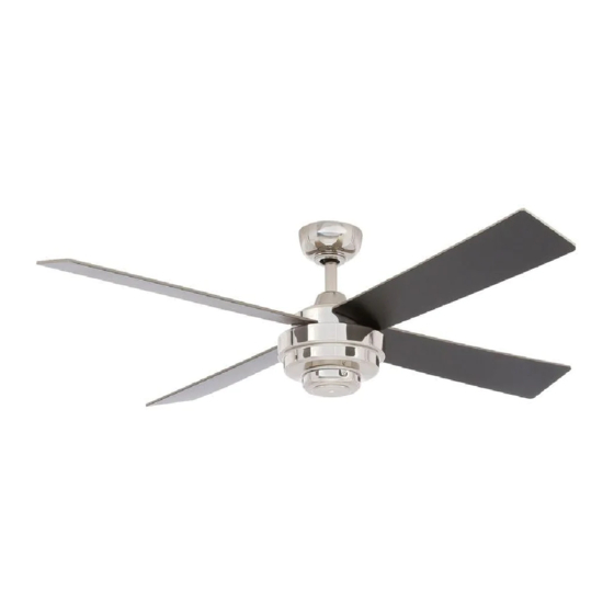
USE AND CARE GUIDE
KEMPER II 52 INCH CEILING FAN
Questions, problems, missing parts? Before returning to the store,
call Hampton Bay Customer Service
8 a.m. - 7 p.m., EST, Monday-Friday, 9 a.m. - 6 p.m., EST Saturday
1-855-HD-HAMPTON
HAMPTONBAY.COM
THANK YOU
THANK YOU
Advertisement
Table of Contents

Related Manuals for HAMPTON BAY AL663A-LN


Summary of Contents for HAMPTON BAY AL663A-LN
- Page 1 USE AND CARE GUIDE KEMPER II 52 INCH CEILING FAN Questions, problems, missing parts? Before returning to the store, call Hampton Bay Customer Service 8 a.m. - 7 p.m., EST, Monday-Friday, 9 a.m. - 6 p.m., EST Saturday 1-855-HD-HAMPTON HAMPTONBAY.COM...
-
Page 2: Table Of Contents
Table of Contents Table of Contents ............Operation ..............Remote Control Operating Instructions ........Safety Information ............Reverse Switch Operating Instructions ........Warranty ................. Care and Cleaning ............Pre-installation .............. Troubleshooting ............Specifications ................Tools Required ................. Service Parts ..............Hardware Included .............. -
Page 3: Safety Information
The fan must be mounted with a minimum of 7 ft. (2.1m) responsible for this declaration: clearance from the trailing edge of the blades to the floor. Model Number: AL663A-LN Company Name: TAL INTERNATIONAL CORPORATION Avoid placing objects in the path of the blades. -
Page 4: Warranty
Warranty The manufacturer warrants the fan motor to be free from defects in workmanship and material present at time of shipment from the factory for a period of lifetime after the date of purchase by the original purchaser. The manufacturer warrants the light kit (excluding any glass), to be free from defects in workmanship and material at the time of shipment from the factory for a period of three years after the date of purchase by the original purchaser. -
Page 5: Hardware Included
Pre-Installation (continued) HARDWARE INCLUDED HARDWARE INCLUDED NOTE: Hardware not shown to actual size. Part Part Description Description Quantity Quantity Plastic wire nut Blade attachment screws with fiber washer 12V battery Balancing kit Plastic wire nut HAMPTONBAY.COM Please contact 1-855-HD-HAMPTON for further assistance. -
Page 6: Package Contents
Pre-Installation (continued) PACKAGE CONTENTS PACKAGE CONTENTS Part Part Description Description Quantity Quantity Part Part Description Description Quantity Quantity Mounting bracket (preassembled) Motor housing Canopy Decorative cover Canopy bottom cover (preassembled) Blade Hanger ball / downrod assembly Receiver Coupling cover Remote control Fan motor assembly Remote control holder... -
Page 7: Installation
Installation MOUNTING OPTIONS MOUNTING OPTIONS WARNING: To reduce the risk of fire, electric shock, or NOTE: You may need a longer downrod to maintain proper personal injury, mount the fan to an outlet box marked blade clearance when installing on a steep, sloped ceiling. acceptable for fan support using the screws provided with the The maximum angle allowable is 18°... -
Page 8: Assembly
Assembly Attaching the fan blades WARNING: To reduce the risk of personal injury, do not bend the blades (I) while installing, balancing the blades (I), or cleaning the fan. WARNING: Do not insert foreign objects between rotating fan blades (I). □... - Page 9 Assembly Assembling the fan WARNING: Failure to properly install the cotter pin (GG) could result in the fan loosening and possibly falling. NOTE: If a longer downrod is needed (not included), take out the screw located in the hanger ball, lower the hanger ball and remove the pin.
-
Page 10: Hanging The Fan
Assembly — Hanging the Fan Hanging the fan from the mounting Installing the mounting bracket bracket to the electrical box WARNING: To reduce the risk of fire, electric shock or WARNING: The tab in the ring must rest in the groove of other personal injury, mount the fan only to an outlet box or the hanger ball (D). - Page 11 Assembly — Hanging the Fan (continued) Preparing the receiver and remote control NOTE: The frequencies on your receiver and remote control have been preset at the factory. Before installing the receiver, make sure the dip switches on the receiver and remote control are set to the same frequency.
- Page 12 Assembly — Hanging the Fan (continued) Making the electrical connections Ground conductor Black White WARNING: Check to see that all connections are tight, including ground, and that no bare wire is visible at the wire nuts (except for the ground wire). WARNING: To reduce the risk of electric shock, this fan Outlet Box must be installed with an isolating wall control / switch.
- Page 13 Assembly — Hanging the Fan (continued) Attaching the canopy Installing the canopy bottom cover WARNING: Make sure the tab on the mounting bracket (A) NOTE: Adjust the canopy mounting screws (FF) as properly sits in the groove in the hanger ball / downrod necessary until the canopy (B) and canopy bottom cover (C) assembly (D) before attaching the canopy (B) to the mounting are snug.
-
Page 14: Attaching The Motor Housing
Assembly — Attaching the Motor Housing Attaching the Motor Housing Installing the Decorative Cover □ Install the decorative cover (H) to the motor housing CAUTION: Before starting installation, disconnect the (G) with the screws (LL) provided. power by turning off the circuit breaker or removing the fuse at the fuse box. -
Page 15: Operation
Operation REMOTE CONTROL OPERATING INSTRUCTIONS REMOTE CONTROL OPERATING INSTRUCTIONS □ Install the 12V MN21/A23 battery (CC) (included) into the remote control (K). To prevent damage to the remote control (K), remove the battery if not used for long periods. □ Restore power to the ceiling fan and test for proper operation. HI, MED, LOW buttons: set the fan speed. -
Page 16: Reverse Switch Operating Instructions
Operation (continued) REVERSE SWITCH OPERATING INSTRUCTIONS REVERSE SWITCH OPERATING INSTRUCTIONS The reverse switch is located on the top of the fan housing. Slide the switch to the left for warm weather operation. Slide the switch Reverse switch to the right for cool weather operation. NOTE: Wait for the fan to stop before reversing the direction of the blade rotation. -
Page 17: Troubleshooting
Troubleshooting WARNING: Make sure the power is off at the electrical panel box before you attempt any repairs. Refer to step 7 “Making the electrical connections” on page 12. Problem Problem Solution Solution □ Check the main and branch circuit fuses or breakers. □... -
Page 18: Service Parts
Service Parts Part Part Description Description Part Part Description Description Mounting bracket (preassembled) Plastic wire nut Canopy Blade attachment screws with Fiber washer Canopy bottom cover (preassembled) 12V battery Hanger ball / downrod assembly Balancing kit Coupling cover Plastic wire nut Fan motor assembly Motor housing Decorative cover... - Page 19 Questions, problems, missing parts? Before returning to the store, call Hampton Bay Customer Service 8 a.m. - 7 p.m., EST, Monday-Friday, 9 a.m. - 6 p.m., EST Saturday 1-855-HD-HAMPTON HAMPTONBAY.COM Retain this manual for future use.