Rockwell Automation Allen-Bradley SLC 500 User Manual
Ethernet/ip adapter
Hide thumbs
Also See for Allen-Bradley SLC 500:
- User manual (84 pages) ,
- Installation instructions manual (20 pages) ,
- Installation instructions manual (24 pages)

Related Manuals for Rockwell Automation Allen-Bradley SLC 500


Summary of Contents for Rockwell Automation Allen-Bradley SLC 500
- Page 1 SLC 500 EtherNet/IP Adapter Catalog Number 1747-AENTR User Manual Original Instructions...
- Page 2 If this equipment is used in a manner not specified by the manufacturer, the protection provided by the equipment may be impaired. In no event will Rockwell Automation, Inc. be responsible or liable for indirect or consequential damages resulting from the use or application of this equipment.
-
Page 3: Table Of Contents
Subnet Mask ..........23 Use the Rockwell Automation BootP/DHCP Utility ....24 Save the Relation List . - Page 4 Use the Device Services Page ....... . . 71 Rockwell Automation Publication 1747-UM076E-EN-E - August 2021...
- Page 5 ..............77 Rockwell Automation Publication 1747-UM076E-EN-E - August 2021...
- Page 6 Table of Contents Notes: Rockwell Automation Publication 1747-UM076E-EN-E - August 2021...
-
Page 7: About This Publication
Industrial Automation Wiring and Grounding Guidelines, publication 1770-4.1 Provides general guidelines for installing a Rockwell Automation industrial system. Product Certifications website, rok.auto/certifications. Provides declarations of conformity, certificates, and other certification details. You can view or download publications at rok.auto/literature. - Page 8 Notes: Rockwell Automation Publication 1747-UM076E-EN-E - August 2021...
-
Page 9: Overview
• a maximum of 96 Class 1 connections; • up to 8 Class 3 connections. For the complete list of supported I/O modules, see the table, List of I/O Modules Supported by the 1747-AENTR Adapter on page Rockwell Automation Publication 1747-UM076E-EN-E - August 2021... -
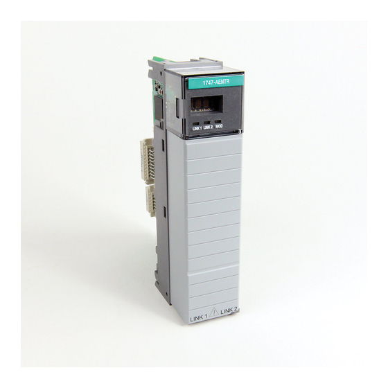
Page 10: Hardware Components
Latch Link 1 status indicator Front cover 5.72 Link 1 Link 2 RJ-45 Ethernet connectors Side view Front view 45845 45846 Right side view Left side view Ethernet connectors (RJ-45) 45844 Bottom view Rockwell Automation Publication 1747-UM076E-EN-E - August 2021... -
Page 11: The 1747-Aentr In A Logix System
Control of real-time I/O data (also known as implicit messaging) – the adapter serves as a bridge between I/O modules and the network • Support of messaging data for configuration and programming information (also known as explicit messaging) Rockwell Automation Publication 1747-UM076E-EN-E - August 2021... -
Page 12: Use Of The Common Industrial Protocol (Cip)
Logix controller and a 1746/1747 I/O module through the 1747-AENTR adapter. Direct I/O connections occur at a cyclic rate specified by the RPI during configuration. Rockwell Automation Publication 1747-UM076E-EN-E - August 2021... -
Page 13: Chapter Summary
See the EtherNet/IP Network Devices User Manual, publication ENET-UM006, for more information on connections. Chapter Summary This chapter provided an overview of the module features, what it does, and its function in a Logix system. Rockwell Automation Publication 1747-UM076E-EN-E - August 2021... - Page 14 Chapter 1 About the SLC 500 EtherNet/IP Adapter Notes: Rockwell Automation Publication 1747-UM076E-EN-E - August 2021...
-
Page 15: Set The Network Address Switches
If the switches are set to an invalid number (for example, 000 or a value greater than 254 excluding 888), the adapter checks to see if DHCP is enabled. Setting the switches to 888 restores default factory settings. Rockwell Automation Publication 1747-UM076E-EN-E - August 2021... -
Page 16: Enable Or Disable The Web Server
Disabled” displays, change the value of the switch based on your IP address mode and cycle power to the adapter. The following section describes how to enable or disable the web server based on the IP address mode that is used. Rockwell Automation Publication 1747-UM076E-EN-E - August 2021... - Page 17 3. In RSLinx software, change the Port Configuration setting to “Manual IP”, set the desired IP address, and cycle power to the adapter. 4. In your web browser, enter the IP address of the adapter. The web server home page displays. Rockwell Automation Publication 1747-UM076E-EN-E - August 2021...
-
Page 18: Determine Power Requirements
3. Install the module in slot 0 of the chassis by aligning the circuit board with the chassis card guide. The 1747-AENTR module must be installed only in slot 0 (leftmost slot)of the chassis. Rockwell Automation Publication 1747-UM076E-EN-E - August 2021... -
Page 19: Connect Your Adapter To The Ethernet/Ip Network Through Rj-45 Connection
This could cause an explosion in hazardous location installations. Be sure that power is removed or the area is nonhazardous before proceeding. 1. Attach the cables with the RJ-45 connectors to the two Ethernet ports on the bottom of the module. Rockwell Automation Publication 1747-UM076E-EN-E - August 2021... -
Page 20: Chapter Summary
IMPORTANT To install systems with rack extensions, you can see the SLC 500 Modular Hardware Style User Manual, publication 1747-UM011. Chapter Summary This chapter provided instructions on how to install and wire the module. It also included power requirements for the module. Rockwell Automation Publication 1747-UM076E-EN-E - August 2021... -
Page 21: Configuration Requirements
Before you can use your adapter, you must configure its IP address, its subnet Requirements mask, and, optionally, a gateway address. You can use the Rockwell Automation BootP utility, version 2.3 or later, to perform the configuration. You can also use a DHCP server or the network address switches to configure these parameters. -
Page 22: Gateway Address
C directly. When host B communicates with host A, it knows from A’s IP address that A is on another network (the network IDs are different). In order to send data to A, Rockwell Automation Publication 1747-UM076E-EN-E - August 2021... -
Page 23: Subnet Mask
Hosts B and C will use Gateway G to communicate with hosts not on Network 2.1. When B is communicating with D, G (the configured Gateway for B) will route the data from B to D through G2. Rockwell Automation Publication 1747-UM076E-EN-E - August 2021... -
Page 24: Use The Rockwell Automation Bootp/Dhcp Utility
Chapter 3 Configure the Adapter for Your EtherNet/IP Network Use the The Rockwell Automation BootP/DHCP utility is a standalone program that Rockwell Automation incorporates the functionality of standard BootP software with a user friendly graphical interface. It is located in the Utility directory on the RSLogix 5000 BootP/DHCP Utility software installation CD. -
Page 25: Save The Relation List
You must have an entry for the device in the Relation List panel to re- enable DHCP. Save the Relation List You can save the Relation List for later use. To save the Relation List, perform the following steps: 1. Select Save As... from the File menu. Rockwell Automation Publication 1747-UM076E-EN-E - August 2021... -
Page 26: Use Dhcp Software To Configure Your Adapter
Failure to observe this precaution may result in unintended machine motion or loss of process control. Chapter Summary This chapter described the requirements and procedures for configuring the IP address, subnet mask, and optional Gateway address. Rockwell Automation Publication 1747-UM076E-EN-E - August 2021... -
Page 27: 1747 I/O Modules
DC Digital Input Module 1746-NT4 Thermocouple/mV Input Module 1746-IV8 DC Digital Input Module Analog Input Module 1746-NI16V 1746-IV16 DC Digital Input Module Analog Input Module 1746-NI16I 1746-IV32 DC Digital Input Module RTD/Resistance Input Module 1746-NR8 Rockwell Automation Publication 1747-UM076E-EN-E - August 2021... - Page 28 1747-AENTR, as of the date of writing of this User Manual. Consult the manufacturer of any third party module to determine if the module is supported by the 1747-AENTR adapter. Rockwell Automation Publication 1747-UM076E-EN-E - August 2021...
-
Page 29: Overview Of Adapter Operation
List of I/O Modules Supported by the 1747-AENTR Adapter on page The module employs the Rockwell Automation Embedded Switch Toolkit. This implementation is an IEEE 802.3 standard compliant, Layer 2 switch that is compatible with the IEEE 802.1 ID standard. It has three ports: two are external ports that function as physical ports of the product and one is an internal port that connects to the host CPU. -
Page 30: Module Keying
Hold last state Write Safe State data to outputs For comprehensive information about Ethernet/IP networks, consult the following resources: • Ethernet Reference Manual, publication ENET-RM002 • EtherNet/IP Network Devices User Manual, publication ENET-UM006 Rockwell Automation Publication 1747-UM076E-EN-E - August 2021... -
Page 31: Chapter Summary
Chapter 4 Plan to Use Your EtherNet/IP Adapter Chapter Summary This chapter provided an overview of adapter operation on an EtherNet/IP network that can assist you in configuring your system. Rockwell Automation Publication 1747-UM076E-EN-E - August 2021... - Page 32 Chapter 4 Plan to Use Your EtherNet/IP Adapter Notes: Rockwell Automation Publication 1747-UM076E-EN-E - August 2021...
-
Page 33: Overview
1 and a 1756-EN2TR bridge module in slot 3. The 1747-AENTR adapter is mounted on an SLC chassis in slot 0, with a 1746-IO8 input module in slot 1, a 1746-IA4 module in slot 2, a 1746-BAS/B module in slot 3, and a power supply. Rockwell Automation Publication 1747-UM076E-EN-E - August 2021... -
Page 34: Create The Example Application
Create the Example Perform the following steps to create the example application: Application 1. Start RSLogix 5000 Enterprise Series software to open the RSLogix 5000 software main dialog. 2. From the File menu, select New. Rockwell Automation Publication 1747-UM076E-EN-E - August 2021... -
Page 35: Configure The I/O
Add the Local EtherNet/IP Bridge to the I/O Configuration 1. Right-click the I/O Configuration folder in the project dialog, and choose New Module from the dropdown list. Rockwell Automation Publication 1747-UM076E-EN-E - August 2021... - Page 36 4. Enter values for Name, IP Address, Slot, Electronic Keying, and Revision, noting that we used the following values: Name EN2TR IP Address 10.88.70.4 Slot Electronic Keying Compatible Module Revision 5. Click OK to accept the configuration. Rockwell Automation Publication 1747-UM076E-EN-E - August 2021...
-
Page 37: Add The Adapter To The I/O Configuration
Configuration 1756-EN2TR module. 1. In the Project dialog, right-click the local 1756-EN2TR module under the I/O Configuration folder, and select New Module. The Select Module Type dialog opens. 2. Choose 1747-AENTR. Click Create. Rockwell Automation Publication 1747-UM076E-EN-E - August 2021... - Page 38 None (only choice available) Chassis Size Electronic Keying Compatible Module Revision IMPORTANT The chassis size value equals 1 (for the adapter) plus the number of I/O modules installed or physically present on the I/O backplane. Rockwell Automation Publication 1747-UM076E-EN-E - August 2021...
-
Page 39: Add I/O Modules To The I/O Configuration
This example application uses I/O module default configurations. For more information, refer to the SLC 500 Systems Selection Guide, publication 1747-SG001. 1. Right-click the name of the 1747-AENTR adapter under the I/O Configuration folder and select New Module. Rockwell Automation Publication 1747-UM076E-EN-E - August 2021... - Page 40 The New Module dialog opens. 3. Enter values for Name and Slot, noting that we used the following values. Name TEST_1746IO8 Slot 4. Select the Connection tab. The RPI is selectable since it is a direct connection. Rockwell Automation Publication 1747-UM076E-EN-E - August 2021...
- Page 41 I/O adapter. IMPORTANT The default RPI of 20 ms is suitable for typical applications. Rockwell Automation recommends that you check or enable the option “Major Fault On Controller If Connection Fails While in Run Mode” on both the 1747-AENTR device and supported 1746 I/O modules.
-
Page 42: Add Specialty I/O Modules Using Advanced Connection
1. In the I/O Configuration tree, right-click SLC Chassis or 1747-AENTR and choose New Module... 2. On the Select Module Type dialog that appears, select 1746-BAS/B and click Create. 3. Enter a name for the device. Rockwell Automation Publication 1747-UM076E-EN-E - August 2021... - Page 43 (but the backplane scan may waste cycles reading input data that will never be used). 5. Click OK on the Module Definition screen. Then, click Yes on the RSLogix 5000 change confirmation screen that appears. Rockwell Automation Publication 1747-UM076E-EN-E - August 2021...
- Page 44 Note that Connection is set as Exclusive Owner - Advanced by default. IMPORTANT The default RPI of 20 ms is suitable for typical applications. Rockwell Automation recommends that you check or enable the option “Major Fault On Controller If Connection Fails While in Run Mode” on both the 1747-AENTR device and supported 1746 I/O modules.
- Page 45 - Offset = 0 8. Click OK to save the configuration. 9. On the Controller Organizer window, right-click Controller Tags under the Controller <name> folder. Select Monitor Tags. 10. Examine the tags created for 1746-BAS/B. Rockwell Automation Publication 1747-UM076E-EN-E - August 2021...
-
Page 46: Download The Program To The Controller
2. Navigate to select the slot where the controller is located in the chassis. 3. Choose Set Project Path. 4. Choose Download. The Download dialog opens with a reminder of the following. • The controller is in Remote Run mode. Rockwell Automation Publication 1747-UM076E-EN-E - August 2021... -
Page 47: Custom Settings (Edit Adapter Configuration)
This information is used to communicate data between the controller and module. Follow these steps to modify the default adapter configuration. 1. In the Project dialog, right-click the 1747-AENTR adapter under I/O Configuration. Rockwell Automation Publication 1747-UM076E-EN-E - August 2021... - Page 48 Rockwell Automation recommends that you check or enable the option “Major Fault On Controller If Connection Fails While in Run Mode” on both the 1747-AENTR device and supported 1746 I/O modules.
- Page 49 2. From the Current Port Speed pull-down menu, choose a port duplex settings speed. 3. From the Current Duplex pull-down menu, choose the appropriate Duplex value, that is, Half Duplex or Full Duplex. Rockwell Automation Publication 1747-UM076E-EN-E - August 2021...
-
Page 50: Custom Settings For Your I/O Module
I/O Module IMPORTANT To fully customize the settings of your I/O module, consult the User Manual for your module. User Manuals and other reference publications for 1746/1747 modules are available in the Rockwell Automation Literature Library: rok.auto/literature You can edit the default configuration of your 1746/1747 module through the Module Properties dialog available in RSLogix 5000. - Page 51 • Exclusive Owner – Advanced (default) • Listen Only – Advanced • Input Only – Advanced To learn more about the different types of connections, see Module Connections on page Rockwell Automation Publication 1747-UM076E-EN-E - August 2021...
- Page 52 Module Fault appears in the text box if a fault occurs when the module is online. To edit the parameters in the Configuration tab, consult the User Manual specific to your I/O module. Rockwell Automation Publication 1747-UM076E-EN-E - August 2021...
-
Page 53: Online Monitoring
Status line indicates module fault Chapter Summary This chapter provided instructions on how to configure the EtherNet/IP adapter for direct connection through the RSLogix 5000 software. Rockwell Automation Publication 1747-UM076E-EN-E - August 2021... - Page 54 Chapter 5 Configure the Adapter for Direct Connection through the RSLogix 5000 or Logix Designer Application Notes: Rockwell Automation Publication 1747-UM076E-EN-E - August 2021...
-
Page 55: Interpret The Indicators
Link 1 and Link 2 status indicator – indicates the port speed and activity on Ethernet ports 1 and 2. Four character display Module status indicator Link 1 and Link 2 status indictators 45847 Rockwell Automation Publication 1747-UM076E-EN-E - August 2021... - Page 56 AENTR remains in this Restored. Change restored switch to something mode until the switches Address Switches and other than 888. are changed. Reset.” Replace the adapter in the chassis, and apply power. Runtime Rockwell Automation Publication 1747-UM076E-EN-E - August 2021...
-
Page 57: Chapter Summary
3), or gone into a Technical Support if state from which it problem persists. cannot recover. Chapter Summary This chapter described the different status indicators that can help you troubleshoot the module. Rockwell Automation Publication 1747-UM076E-EN-E - August 2021... - Page 58 Chapter 6 Troubleshoot with the Status Indicators Notes: Rockwell Automation Publication 1747-UM076E-EN-E - August 2021...
- Page 59 IEC 60068-2-6 (Test Fc, Operating): Vibration 2.5g @ 57…2000Hz IEC 60068-2-27 (Test Ea, Unpackaged Shock): Shock, operating 30 g IEC 60068-2-27 (Test Ea, Unpackaged Shock): Shock, nonoperating 50 g Emissions CISPR 11: Group 1, Class A Rockwell Automation Publication 1747-UM076E-EN-E - August 2021...
- Page 60 Korean Registration of Broadcasting and Communications Equipment, compliant with: Article 58-2 of Radio Waves Act, Clause 3 (1) See the Product Certification link at rok.auto/certifications for Declaration of Conformity, Certificates, and other certification details. Rockwell Automation Publication 1747-UM076E-EN-E - August 2021...
-
Page 61: Overview
To display and work with the adapter diagnostics home page, follow these procedures. IMPORTANT Make sure that your PC Internet LAN setting and your TCP/IP settings are configured to access the subnet on which your adapter communicates. Rockwell Automation Publication 1747-UM076E-EN-E - August 2021... -
Page 62: Work With The Diagnostics
• Click one of the following to access www.ab.com. - Allen-Bradley logo at the top of the page • Click Rockwell Automation at the top right to go to www.rockwellautomation.com. • Click the following to see additional diagnostics web pages. -
Page 63: Use The Diagnostic Overview Page
Click tabs to see the corresponding page Click Diagnostics options to see corresponding pages Type a refresh rate Use the Diagnostic Overview Page To use the Diagnostic Overview page for general diagnostics information, follow this procedure. Rockwell Automation Publication 1747-UM076E-EN-E - August 2021... - Page 64 - Max Msg Connections Observed - Current CIP I/O Connections - CIP I/O Connection Limit - Max I/O Connections Observed - Conn Opens - Open Errors - Conn Closes - Close Errors - Conn Timeout Rockwell Automation Publication 1747-UM076E-EN-E - August 2021...
-
Page 65: Use The Network Settings Page
- Primary Name Server - Secondary Name Server - Default Domain Name - Host Name - Name Resolution • Ethernet Interface Configuration - How the Network Configuration was obtained - Static or Dynamic Rockwell Automation Publication 1747-UM076E-EN-E - August 2021... -
Page 66: Use The Ethernet Statistics Page
The Ethernet Statistics page opens. 2. From the Ethernet Statistics page, you can view the following: • Ethernet Port 1 and Port 2 - Interface State - Link Status - Media Speed - Duplex - Autonegotiate Status Rockwell Automation Publication 1747-UM076E-EN-E - August 2021... -
Page 67: Use The I/O Connections Page
The I/O Connections page opens. The top value in this column representing Lost shows the number of packets from the missing source. 2. From the I/O Connections page, view the following: • Connection Number • Uptime Rockwell Automation Publication 1747-UM076E-EN-E - August 2021... -
Page 68: Work With The Configuration
2. From the Configuration page, click one of the following: • Identity • Network • Services A login dialog opens as shown. The dialog may vary in appearance depending on your operating system and browser. Rockwell Automation Publication 1747-UM076E-EN-E - August 2021... -
Page 69: Use The Device Identity Page
3. Click Apply Changes to save the modified values. Use the Network Configuration Page To use the Network Configuration page to make entries for enabling or disabling DHCP and setting TCP/IP parameters and Ethernet link operation, follow this procedure. Rockwell Automation Publication 1747-UM076E-EN-E - August 2021... - Page 70 - Primary Name Server - Secondary Name Server - Domain Name • For Ethernet Link Port 1 and Port 2, specify the following: - Autonegotiate Status - Autonegotiate Speed and Duplex - Force Speed and Duplex Rockwell Automation Publication 1747-UM076E-EN-E - August 2021...
-
Page 71: Use The Device Services Page
• Change the password by typing a new value for New Password and Confirm Password, noting the following: - The entry is case sensitive. - The default value is <blank>. 3. Click Apply Changes. Rockwell Automation Publication 1747-UM076E-EN-E - August 2021... - Page 72 Appendix B Adapter Web Dialogs Notes: Rockwell Automation Publication 1747-UM076E-EN-E - August 2021...
- Page 73 ROM drive letter. 4. Click OK. The progress bar, followed by the welcome screen opens Configure the AB_ETH/IP To configure the AB-ETHIP Ethernet communication driver, perform the Driver following steps. 1. Start the RSLinx software. Rockwell Automation Publication 1747-UM076E-EN-E - August 2021...
- Page 74 3. Select EtherNet/IP Devices from the list and click Add/New... The Configure Dialog box opens. Make sure the Browse Local Subnet button is selected. The RSLinx software browses your local subnet and automatically reads the IP address. Rockwell Automation Publication 1747-UM076E-EN-E - August 2021...
- Page 75 Appendix C Configure the RSLinx Ethernet Communication Driver 4. Click OK. The AB-ETHIP driver is now configured and appears in the configured drivers window. 5. Close the RSLinx software. Rockwell Automation Publication 1747-UM076E-EN-E - August 2021...
- Page 76 Appendix C Configure the RSLinx Ethernet Communication Driver Notes: Rockwell Automation Publication 1747-UM076E-EN-E - August 2021...
- Page 77 33 add 1747-AENTR 37 for direct connection 33 add I/O module 39 connection 33 I/O configuration direct 29 add Ethernet bridge 35 maximum 29 IEEE 802.1 ID 29 simple 42 IEEE 802.3 29 Rockwell Automation Publication 1747-UM076E-EN-E - August 2021...
- Page 78 59 I/O Connections 67 network settings 65 relation list 25 weight 59 relative humidity 59 wiring category 59 requirements 29 configuration 21 power 18 RJ-45 10 wire 19 RPI 12 default value 41 Rockwell Automation Publication 1747-UM076E-EN-E - August 2021...
- Page 79 SLC 500 EtherNet/IP Adapter User Manual Rockwell Automation Publication 1747-UM076E-EN-E - August 2021...
- Page 80 Rockwell Automation maintains current product environmental compliance information on its website at rok.auto/pec. Allen-Bradley, CompactLogix, ControlLogix, expanding human possibility, FactoryTalk, Logix 5000, PanelView, Rockwell Automation, RSLinx, RSLogix 5000, SLC, SLC 500, Studio 5000, Studio 5000 Logix Designer, and TechConnect are trademarks of Rockwell Automation, Inc.