Table of Contents
Advertisement
Quick Links
Advertisement
Table of Contents

Related Manuals for Rockwell Automation Allen-Bradley PowerFlex 20-COMM-L


Summary of Contents for Rockwell Automation Allen-Bradley PowerFlex 20-COMM-L
- Page 1 LonWorks Adapter 20-COMM-L FRN 1.xxx User Manual...
- Page 2 Important User Information Solid state equipment has operational characteristics differing from those of electromechanical equipment. “Safety Guidelines for the Application, Installation and Maintenance of Solid State Controls” (Publication SGI-1.1) describes some important differences between solid state equipment and hard-wired electromechanical devices. Because of this difference, and also because of the wide variety of uses for solid state equipment, all persons responsible for applying this equipment must satisfy themselves that each intended application of this equipment is acceptable.
- Page 3 Summary of Changes This is the first release of the LonWorks adapter FRN1.xxx.
- Page 4 S-ii Summary of Changes...
-
Page 5: Table Of Contents
Conventions Used in This Manual ..... P-1 Rockwell Automation Support......P-2... - Page 6 Table of Contents Chapter 5 Troubleshooting Locating the Status Indicators ......5-1 PORT Status Indicator ......5-2 MOD Status Indicator .
-
Page 7: Preface
Preface About This Manual Topic Page Related Documentation Conventions Used in This Manual Rockwell Automation Support Related Documentation For: Refer to: Publication DriveExplorer™ DriveExplorer Getting Started Manual 9306-GR001… DriveExplorer Online Help DriveTools 2000™ DriveTools 2000 Online Help HIM Quick Reference 20HIM-QR001…... -
Page 8: Rockwell Automation Support
Contact your local Rockwell Automation representative for sales and order support, product technical training, warranty support, and support service agreements. Technical Product Assistance If you need to contact Rockwell Automation for technical assistance, please review the information in Chapter 5, Troubleshooting, first. If you still have problems, then call your local Rockwell Automation representative. -
Page 9: Getting Started
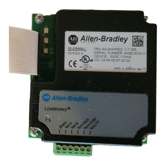
Chapter Getting Started Chapter 1 provides information about the 20-COMM-L LonWorks adapter, an embedded communication option specifically for PowerFlex 70 and 700 (Standard) drives. Topic Page Topic Components Safety Precautions Features Quick Start Compatible Products Modes of Operation Required Equipment Components Figure 1.1 Components of the Adapter –... -
Page 10: Features
Getting Started Features The LonWorks adapter features the following: • The adapter is mounted in the drive and receives its required power from the drive. • Status indicators report the status of the drive communications, adapter, and network. They are visible both when the drive cover is opened and when it is closed. -
Page 11: Required Equipment
Getting Started Required Equipment Equipment Shipped with the Adapter When you unpack the adapter, verify that the package includes: ❑ One LonWorks adapter ❑ A 2.54 cm (1 in.) and a 15.24 cm (6 in.) Internal Interface cable (only one cable is needed to connect the adapter to the drive) ❑... - Page 12 There are many variables and requirements with any application. Rockwell Automation does not assume responsibility or liability (to include intellectual property liability) for actual use of the examples shown in this publication.
-
Page 13: Quick Start
Getting Started Quick Start This section is designed to help experienced users start using the LonWorks adapter. If you are unsure how to complete a step, refer to the referenced chapter Step Action Refer to Review the safety precautions for the adapter. Throughout this manual Verify that the drive is properly installed. -
Page 14: Modes Of Operation
Getting Started Modes of Operation The adapter uses four status indicators to report its operating status. They can be viewed on the adapter or through the drive cover. Figure 1.2 Status Indicators (location on drive may vary) – — ˜ –... -
Page 15: Installing The Adapter
Chapter Installing the Adapter Chapter 2 provides instructions for installing the LonWorks adapter in a PowerFlex 70 or 700 drive. Topic Page Preparing for the Installation Connecting the Adapter to the Network Connecting the Adapter to the Drive Applying Power Preparing for the Installation Before installing the adapter, verify that you have all required equipment. - Page 16 Installing the Adapter 4. Connect a cable to the network, and route it through the bottom of the drive. (See Figure 2.3 on page 2-4. Refer to the LonMark Layers 1-6 Interoperability Guidelines, Appendix A “Cable Requirements for the TP/FT-10 Channel.”) 5.
-
Page 17: Connecting The Adapter To The Drive
Installing the Adapter Connecting the Adapter to the Drive 1. Remove power from the drive and network. 2. Use static control precautions. 3. Connect the Internal Interface cable to the DPI port on the drive and then to the DPI connector on the adapter. Figure 2.2 DPI Ports and Internal Interface Cables –... - Page 18 Installing the Adapter 4. Secure and ground the adapter to the drive by doing the following: – On a PowerFlex 70, fold the Internal Interface cable behind the adapter and mount the adapter on the drive using the four captive screws.
-
Page 19: Applying Power
Installing the Adapter Applying Power ATTENTION: Risk of equipment damage, injury, or death exists. Unpredictable operation may occur if you fail to verify that parameter settings are compatible with your application. Verify that settings are compatible with your application before applying power to the drive. 1. - Page 20 Installing the Adapter Notes:...
-
Page 21: Configuring The Adapter
Chapter Configuring the Adapter Chapter 3 provides instructions for setting the parameters in the adapter. Topic Page Topic Page Configuration Tools Setting the Idle Fault Action Using the PowerFlex HIM Resetting the Adapter Setting the I/O Configuration Viewing the Adapter Configuration 3-7 Setting the Comm Fault Action For a list of parameters, refer to Appendix... -
Page 22: Using The Powerflex Him
Configuring the Adapter Using the PowerFlex HIM If your drive has either an LED or LCD HIM (Human Interface Module), access parameters in the adapter as follows: Using an LED HIM Step Key(s) Example Screens 1. Press the ALT key and then the Device Sel (Device) key to display the Device Screen. -
Page 23: Setting The I/O Configuration
Configuring the Adapter Setting the I/O Configuration The I/O configuration determines the type of data sent to the drive. Logic Command/Status and Datalinks may be enabled or disabled. 1. Set the bits in Parameter 9 - [DPI I/O Cfg]. A “1” enables the I/O. -
Page 24: Setting The Comm Fault Action
Configuring the Adapter Setting the Comm Fault Action By default, when communications are disrupted (for example, a cable is disconnected), the drive will remain in its current state (e.g. a running drive will continue to run) until Parameter 7 - [RcvHrtBeat Time] has elapsed. -
Page 25: Setting The Idle Fault Action
Configuring the Adapter • Setting Parameter 7 - [RcvHrtBeat Time] to “0” disables the fault action, and a value greater than “0” enables the fault action. If nviDrvSpeedStpt is not received by the adapter within the Parameter 7 - [RcvHrtBeat Time] value, the fault action in Parameter 6 - [Comm Flt Action] will be taken. -
Page 26: Resetting The Adapter
Configuring the Adapter To set the fault configuration parameters If you set Parameter 6 - [Comm Flt Action] or Parameter 8 - [Idle Flt Action] to “Send Flt Cfg,” the values in the following parameters are sent to the drive after a communications fault occurs. You must set these parameters to values required by your application. -
Page 27: Viewing The Adapter Configuration
Configuring the Adapter Viewing the Adapter Configuration The following parameters provide information about how the adapter is configured. You can view these parameters at any time. Parameter No. Name and Description Details [Ref/Fdbk Size] Default: 0 = 16-bit Displays the size of the reference and feedback Values: 0 = 16-bit as set in the ping message. - Page 28 Configuring the Adapter Parameter No. Name and Description Details Idle Flt Action] Default: 0 = Fault Sets the action that the adapter will take during Values: 0 = Fault offline/disable occurrences. 1 = Stop 2 = Zero Data 3 = Hold Last 4 = Send Flt Cfg Type: Read/Write...
-
Page 29: Configuring The Lonworks Network
Chapter Configuring the LonWorks Network Chapter 4 provides information about configuring network variables to access a PowerFlex 70 or 700 drive when using a LonWorks adapter. Topic Page Overview of LonWorks Functionality Operating the Drive Using a LonMark Profile Node Operations Network Variable Inputs (NVIs) Network Variable Outputs (NVOs) Network Configuration Inputs (NCIs) -
Page 30: Operating The Drive Using A Lonmark Profile
Configuring the LonWorks Network Operating the Drive Using a LonMark Profile A LonMark profile defines the functional profile for a node communicating with other nodes. The profile specifies which SNVTs (Standard Network Variable Types) and SCPTs (Standard Configuration Property Types) are used, and provides a semantic meaning about the information being communicated. - Page 31 Configuring the LonWorks Network Figure 4.2 Drive Object Variable Speed Motor Drive: 6010 Mandatory Network nvoDrvSpeed nviDrvSpeedStpt SNVT_switch SNVT_lev_percent Variables nvoDrvCurnt SNVT_amp Optional nvoDrvVolt SNVT_volt nviDrvSpeedScale Network SNVT_lev_percent nvoDrvPwr Variables SNVT_power_kilo nvoDrvRunHours SNVT_time_hour Configuration Properties nc50 - nciMaxSpeed nc53 - nciMinSpeed nc48 - nciRcvHrtBt nc49 - nciSndHrtBt nc52 - nciMinOutTm...
-
Page 32: Node Operations
Configuring the LonWorks Network Node Operations The following sections describe the basics of node operation. WINK (What is a WINK?) WINK is a network command that verifies communication with a node. The NET A indicator will flash to indicate that a WINK was received. The LED will flash red according to the following sequence: •... -
Page 33: Network Variable Inputs (Nvis)
Configuring the LonWorks Network Network Variable Inputs (NVIs) This section provides descriptions of the Network Variable Inputs. Node Object Request Variable: nviObjRequest Format: SNVT_obj_request Explanation: This input enables control commands and updates from the network to specific objects in the node. The identification number for the node is 0 and for the drive object is 1. - Page 34 Configuring the LonWorks Network Drive Speed Setpoint Variable: nviDrvSpeedStpt Format: SNVT_switch Explanation: This network variable input provides a speed reference setpoint. When nviDrvSpeedStpt.state is set to zero, the drive is stopped. Valid range: State Value Requested Speed STOPPED 0.5 to 100.0% 0.5 to 100.0% 100.0% 100.0%...
- Page 35 Configuring the LonWorks Network Module Configuration Variable: nviNV_config Format: UNVT_DPI_CONFIG Explanation: This network variable input provides information on how parameters should be mapped to network variables. The NVI contains two fields: • NV_index • DPI_parameter To check an already existing configuration, use the following procedures: •...
- Page 36 Configuring the LonWorks Network NV_index in: 31-36. Default PowerFlex 70/700 Drive LON SNVT NV_Index Parameter nciNmlSpeed nciMinSpeed nciMaxSpeed nciRampUpTm nciRampDownTime 35 nciNmlFreq Default value: This configuration is the default for PowerFlex 70/700 drives. For other future drives, the defaults are 0 and need to be configured prior to network commissioning.
-
Page 37: Network Variable Outputs (Nvos)
Configuring the LonWorks Network Network Variable Outputs (NVOs) This section describes the network variable outputs. No output values are sent over the network, unless they have changed (except nvoDrvSpeed, which is sent for the heartbeat functionality, and nvoObjStatus, if update status is requested). - Page 38 4-10 Configuring the LonWorks Network Drive Current Variable: nvoDrvCurnt Format: SNVT_amp Explanation: This network variable output provides the drive output current in amps. Default PowerFlex 70/700 drive parameter mapping: Parameter 3 - [Output Current]. Can be mapped using the nviNV_config variable. Drive Speed Variable: nvoDrvSpeed Format: SNVT_level_percent...
- Page 39 Configuring the LonWorks Network 4-11 Drive Voltage Variable: nvoDrvVolt Format: SNVT_volt Explanation: This network variable output provides the drive voltage in volts. Default PowerFlex 70/700 drive parameter mapping: Parameter 6 - [Output Voltage]. Can be mapped using the nviNV_config variable. Output Frequency Variable: nvoFreqAct Format: SNVT_freq_hz...
- Page 40 4-12 Configuring the LonWorks Network Configuration Feedback Variable: nvoFB_config Format: SNVT_count Explanation: This network variable output is used to verify that the configuration of the adapter is OK. When changing the configuration with the nviNV_config variable, nvoFB_config responds with the NV_index that was updated. Datalink Outs Variable: nvoDatalinkA1 nvoDatalinkA2...
-
Page 41: Network Configuration Inputs (Ncis)
Configuring the LonWorks Network 4-13 Network Configuration Inputs (NCIs) The values of the NCIs change when written to and keep their values after a power cycle. All NCIs, with a corresponding parameter in the drive, are read from the drive after reset and when going from offline to online. When the parameter is updated from the network, it is written to the drive. - Page 42 4-14 Configuring the LonWorks Network Minimum Send Time NCI: nciMinOutTm Format: SNVT_time_sec Explanation: This network configuration input specifies the minimum period of time that expires before the network variable outputs can be re-sent. All variables are updated if they changed at each period end. This is good for limiting use of bandwidth on the LonWorks network.
- Page 43 Configuring the LonWorks Network 4-15 Nominal Frequency NCI: nciNmlFreq Format: SNVT_freq_hz Explanation: This network configuration input sets the nominal frequency of the motor. Default value: 60 Hz. Default PowerFlex 70/700 drive parameter mapping: Parameter 43 - [Motor NP Hertz]. Can be adjusted using the nviNV_config variable or Parameter 29 - [NmlFreqParam].
- Page 44 4-16 Configuring the LonWorks Network Maximum Speed NCI: nciMaxSpeed Format: SNVT_lev_percent Explanation: This network configuration input specifies the maximum speed of the motor. Its value is entered as a percentage of nominal frequency as defined by the Nominal Frequency (nciNmlFreq) configuration value. For example, if nciNmlFreq = 50 Hz.
- Page 45 Configuring the LonWorks Network 4-17 Ramp Down Time NCI: nciRampDownTm Format: SNVT_time_sec Explanation: This network configuration input sets the deceleration time. The value specifies the length of time it will take to bring the inverter to a stop when running at maximum frequency. Default value: 10.0 sec Default PowerFlex 70/700 drive parameter mapping:...
- Page 46 4-18 Configuring the LonWorks Network Default value: 0 (Not used) Valid range: Any valid drive parameter. Generic Parameter Write Address NCI: nciParWriAdr Format: SNVT_count Explanation: This network configuration input is used to set the parameter number to which a write operation should be performed. The actual data value is collected from nciParWriData.
-
Page 47: Conditions Required For Operation
Configuring the LonWorks Network 4-19 Conditions Required for Operation This section will describe what conditions are required for performing some common actions and how the combination of SNVTs and SCPTs affects the operation of the drive. Starting the Drive The drive will RUN if nviDrvSpeedStpt.state is TRUE. Stopping the Drive The drive stops using the default stop mode if NviSpeedStpt.state is set to zero or if the node is brought offline or disabled, depending on the... -
Page 48: Resource Files
4-20 Configuring the LonWorks Network nciMinOutTm vs. nciSendHrtBt The nciMinOutTm has priority over nciSendHrtBt. This means that heartbeats will not be sent as often as specified in nciSendHrtBt if nciMinOutTm has a longer time set. Error Handling If nciRcvHrtBt is larger than zero, and heartbeats are not received within the nciRcvHrtBt time, then communication with the LonWorks network is considered down. - Page 49 Configuring the LonWorks Network 4-21 In addition to the resource files, the following file types are also used: • Language File - Defines language-dependent strings. There is a separate language file for each supported language. The supported language file determines the extension of a language file. Two language files are currently available for the LonMark standard type files;...
- Page 50 4-22 Configuring the LonWorks Network Notes:...
-
Page 51: Troubleshooting
Chapter Troubleshooting Chapter 5 provides information for troubleshooting potential problems with the adapter and network. Topic Page Topic Page Locating the Status Indicators Viewing and Clearing Adapter Diagnostic Items PORT Status Indicator MOD Status Indicator Viewing and Clearing Events NET A Status Indicator (Service Indicator) Locating the Status Indicators The LonWorks adapter has three status indicators. -
Page 52: Port Status Indicator
Troubleshooting PORT Status Indicator The PORT status indicator is the top LED on the drive. See Figure 5.1. State Cause Corrective Actions • Securely connect the adapter to the The adapter is not powered or is not connected properly to the drive using the ribbon cable. -
Page 53: Mod Status Indicator
Troubleshooting MOD Status Indicator The MOD status indicator is the second LED from the top on the drive. See Figure 5.1. State Cause Corrective Actions • Securely connect the adapter to the The adapter is not powered. drive using the ribbon cable. •... -
Page 54: Net A Status Indicator (Service Indicator)
Troubleshooting NET A Status Indicator (Service Indicator) The NET A status indicator is the third LED from the top on the drive (see Figure 5.1) and is controlled by the Neuron Chip. State Cause Corrective Actions The node is configured. No action. -
Page 55: Viewing And Clearing Adapter Diagnostic Items
Troubleshooting Viewing and Clearing Adapter Diagnostic Items Adapter Diagnostic Items are viewable with DriveExplorer software (version 2.01 or higher), DriveExecutive software (version 1.01 or higher), or a HIM (version 2.001 or higher). Step Keys Example Screen Viewing Diagnostic Items 1. Access parameters in the adapter. Refer to Using the PowerFlex HIM Chapter... - Page 56 Troubleshooting List of Diagnostic Items If you encounter unexpected communications problems, diagnostic items can help you or Rockwell Automation personnel troubleshoot the problem. Name Description Common Logic Current value of the Common Logic Command being transmitted to the host by this peripheral.
- Page 57 Troubleshooting Name Description 28 Last Reset Cause 0 = Power Up 1 = External 2 = Watchdog 3 = Software 4 = Cleared 29 Neuron State The state of the Neuron Chip: 0 = appl_uncnfg 1 = cnfg_online 2 = unknown 3 = cnfg_offline 4 = soft_online 30 Neuron Chip ID...
-
Page 58: Viewing And Clearing Events
Troubleshooting Viewing and Clearing Events The adapter maintains an event queue that reports the history of its actions. You can view this using an LCD PowerFlex HIM, DriveExplorer software (2.01 or higher), or DriveExecutive software (1.01 or higher). Step Keys Example Screen Viewing Events 1. - Page 59 Events Many events in the Event queue occur under normal operation. If you encounter unexpected communications problems, the events can help you or Rockwell Automation personnel troubleshoot the problem. The following events may appear in the event queue: Code Event...
- Page 60 5-10 Troubleshooting Code Event Description LON Reset The peripheral has detected a reset of the Neuron Chip. LON Enabled The Node is enabled by RQ_ENABLE. LON Disabled The Node is disabled by RQ_DISABLE. Language CRC Bad The segment of flash holding the text translations has a bad CRC.
-
Page 61: Specifications
Appendix Specifications Appendix A presents the specifications for the adapter. Topic Page Topic Page Communications Environmental Electrical Regulatory Compliance A-2 Mechanical Communications Network Protocol LonWorks Data Rates 78 kbps Electrical Consumption 200 mA on DPI Mechanical Dimensions Height 20 mm (0.79 in.) Length 86 mm (3.33 in.) Width... -
Page 62: Environmental
Specifications Environmental Temperature Operating -15 to 70° C (5 to 158° F) Storage -40 to 85° C (-40 to 185° F) Relative Humidity 5 to 95% non-condensing Atmosphere Important: The adapter must not be installed in an area where the ambient atmosphere contains volatile or corrosive gas, vapors or dust. -
Page 63: Adapter Parameters
Appendix Adapter Parameters Appendix B presents information about the adapter parameters. Topic Page Parameter List Parameter List Parameter No. Name and Description Details [DPI Port] Default: Displays the port to which the adapter is Minimum: connected. This will usually be port 5. Maximum: Type: Read Only... - Page 64 Adapter Parameters Parameter No. Name and Description Details [Comm Flt Action] Default: 0 = Fault Sets the action that the adapter will take if it Values: 0 = Fault detects that network communications have been 1 = Stop disrupted (if Parameter 7 - [RcvHrtBeat Time] 2 = Zero Data times out before nviDrvSpeedStpt is updated 3 = Hold Last...
- Page 65 Adapter Parameters Parameter No. Name and Description Details [DPI I/O Config] Default: xxx0 0001 Configures the I/O to be transferred through the Bit Values: 0 = I/O disabled adapter. 1 = I/O enabled Type: Read/Write Reset Required: Bit Definitions 0 = Cmd/Ref Default 1 = Datalink A 2 = Datalink B...
- Page 66 Adapter Parameters Parameter No. Name and Description Details [Flt Cfg A1 In] Default: [Flt Cfg A2 In] Default: [Flt Cfg B1 In] Default: [Flt Cfg B2 In] Default: [Flt Cfg C1 In] Default: [Flt Cfg C2 In] Default: [Flt Cfg D1 In] Default: [Flt Cfg D2 In] Default:...
- Page 67 Adapter Parameters Parameter No. Name and Description Details [DrvPwrParam] Default: Sets the PowerFlex drive parameter number to Values: PowerFlex drive be used with nvoDrvPwr. See Chapter parameter numbers Network Variable Outputs (NVOs). Type: Read/Write Setting this parameter’s value to zero disables Reset Required: the firmware from fetching the corresponding parameter value from the drive.
- Page 68 Adapter Parameters Parameter No. Name and Description Details [MinSpeedParam] Default: Sets the PowerFlex drive parameter number to Values: PowerFlex drive be used with nciMinSpeed. See Chapter parameter numbers Network Configuration Inputs (NCIs). Type: Read/Write Reset Required: [RampUpTmParam] Default: Sets the PowerFlex drive parameter number to Values: PowerFlex drive be used with nciRampUpTm.
-
Page 69: Logic Command/Status Words
Appendix Logic Command/Status Words Appendix C provides the definitions of the Logic Command/Logic Status words that are used for some products that can be connected to the LonWorks adapter. If your product is not included here, refer to its documentation. PowerFlex 70 and PowerFlex 700 Drives Logic Command Word Logic Bits... - Page 70 Logic Command/Status Words PowerFlex 70 and PowerFlex 700 Drives Logic Status Word Logic Bits 15 14 13 12 11 10 9 8 7 6 5 4 3 2 1 0 Status Description x Ready 0 = Not Ready 1 = Ready Active 0 = Not Running 1 = Running...
-
Page 71: Glossary
Glossary Binding A process whereby a network variable input and a network variable output are connected together. Binding a network variable tells the device which other devices it should talk to and what information it should share. Only network variables of the same SNVT type can be bound together. - Page 72 Glossary DPI Product A device that uses the DPI communications interface to communicate with one or more peripheral devices. For example, a motor drive such as a PowerFlex drive is a DPI product. In this manual, a DPI product is also referred to as “product”...
- Page 73 Glossary Flash Update The process of updating firmware in the adapter. The adapter can be flash updated using the X-Modem protocol or Control FLASH, and a serial converter. Hold Last When communications are disrupted (for example, a cable is disconnected), the adapter and drive can respond by holding last. Hold last results in the drive receiving the last data received via the network connection before the disruption.
- Page 74 Glossary LonWorks Network Intelligent devices that communicate with each other using the LonWorks protocol over one or more communications channels. LonWorks Protocol The open control networking protocol designed for applications involving sense, monitor, control, and identification functions. Also known as EIA 709.1 Control Networking Standard and as LonTalk protocol.
- Page 75 Glossary Protocols Rules that order how information is transmitted and presented. An “open protocol” is one in which the manufacturer has made the language “translation” available to anyone who wishes to use it. Reference/Feedback The Reference is used to send a reference (for example, speed, frequency, torque) to the product.
- Page 76 Glossary Zero Data When communications are disrupted (for example, a cable is disconnected), the adapter and drive can respond with zero data. Zero data results in the drive receiving zero as values for command data. If the drive was running and using the reference from the adapter, it will stay running but at zero reference.
-
Page 77: Index
Index configuring the LonWorks network, 4-1 to 4-21 adapter connecting an adapter to a drive, 2-3 applying power, 2-5 connecting an adapter to a network, 2-1 compatible products, 1-2 components, 1-1 configuring I/O for, 3-3 connecting to a drive, 2-3 connecting to a network, 2-1 data rate, definition of, G-1 features, 1-2... - Page 78 Index DrvRunHoursParam parameter, B-5 hold last configuring an adapter for, 3-5 DrvSpeedParam parameter, B-4 definition of, G-3 DrvVoltParam parameter, B-5 EEPROM, see Non-Volatile Storage configuring an adapter for, 3-3 (NVS) definition of, G-3 electrical specifications, A-1 Idle Flt Action parameter, B-2 environmental specifications, A-2 installation equipment, 1-3...
- Page 79 Index MOD status indicator locating, 5-1 parameters troubleshooting with, 5-3 accessing, 3-1 modes of operation, 1-6 configuring, 3-1 to 3-8 Module Configuration (NVI), 4-7 factory-default settings, 3-6 mounting an adapter on a drive, 2-4 list of, B-1 to B-6 plug for network cable, 2-2 PORT status indicator locating, 5-1 NCIs (Network Configuration Inputs), 4-13...
- Page 80 Index Speed Setpoint Scaling (NVI), 4-6 status indicators definition of, G-5 MOD, 5-3 NET A, 5-4 normal operation, 1-6 PORT, 5-2 troubleshooting with, 5-1 technical support, P-2 tools, 1-3 transceiver, definition of, G-5 troubleshooting, 5-1 to 5-10 update, see flash update viewing adapter configuration, 3-7 Web page for DriveExplorer software, G-2...
- Page 81 Allen-Bradley, ControlFLASH, DPI, DriveExplorer, DriveTools 2000, DriveExecutive, PowerFlex, and SCANport are trademarks of Rockwell Automation. , LonMaker, LonTalk, Neuron, and LON are trademarks of Echelon ORKS Corporation. Windows, Windows NT, and Microsoft are trademarks of Microsoft Corporation.
- Page 82 Americas: Rockwell Automation, 1201 South Second Street, Milwaukee, WI 53204-2496 USA, Tel: (1) 414.382.2000, Fax: (1) 414.382.4444 Europe/Middle East/Africa: Rockwell Automation SA/NV, Vorstlaan/Boulevard du Souverain 36, 1170 Brussels, Belgium, Tel: (32) 2 663 0600, Fax: (32) 2 663 0640 Asia Pacific: Rockwell Automation, 27/F Citicorp Centre, 18 Whitfield Road, Causeway Bay, Hong Kong, Tel: (852) 2887 4788, Fax: (852) 2508 1846 Headquarters for Dodge and Reliance Electric Products Americas: Rockwell Automation, 6040 Ponders Court, Greenville, SC 29615-4617 USA, Tel: (1) 864.297.4800, Fax: (1) 864.281.2433...
Need help?
Do you have a question about the Allen-Bradley PowerFlex 20-COMM-L and is the answer not in the manual?
Questions and answers