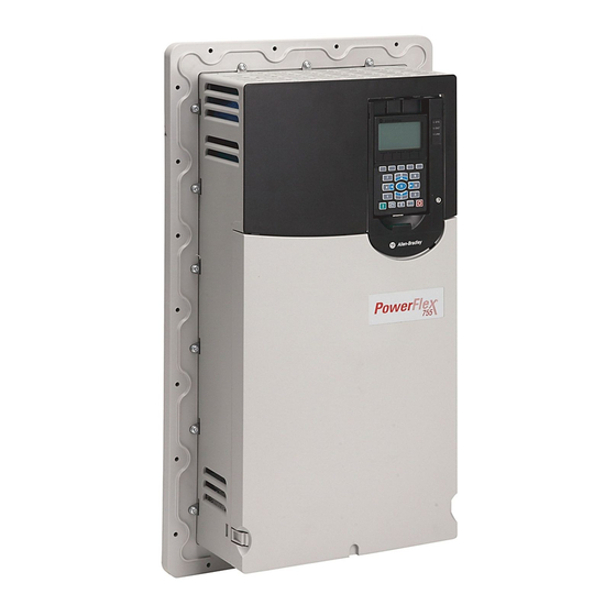
Rockwell Automation Allen-Bradley PowerFlex 755 Installation Instructions Manual
Common dc input drives, frames 8...10 interlock assembly and precharge assembly left-front cover retrofit kit
Hide thumbs
Also See for Allen-Bradley PowerFlex 755:
- Migration manual (46 pages) ,
- Original instructions manual (30 pages) ,
- Installation instructions (4 pages)
Advertisement
Quick Links
Installation Instructions
PowerFlex 755 Common DC Input Drives, Frames 8...10 Interlock Assembly and
Precharge Assembly Left-front Cover Retrofit Kit
Catalog Numbers 20G14x, 21G14x
General Precautions
Before You Begin
Topic
General Precautions
Before You Begin
Install the Retrofit Kit
Additional Resources
This retrofit kit can be used to improve the access to the molded case switch
(SW1) on common DC input drives for lock-out, tag-out procedures. Install this
kit only on DC input with precharge modules with catalog numbers
20-750-P5-C770D740 and 20-750-P5-E510F500.
ATTENTION:
• Only qualified personnel familiar with adjustable frequency AC drives and
associated machinery should plan or implement the installation, start-up and
subsequent maintenance of the system. Failure to comply may result in
personal injury and/or equipment damage.
• This drive contains ESD (Electrostatic Discharge) sensitive parts and assemblies.
Static control precautions are required when you install, test, service, or repair
this assembly. Component damage may result if ESD control procedures are not
followed. If you are not familiar with static control procedures, reference
Guarding Against Electrostatic Damage, publication 8000-4.5.2 or any other
applicable ESD protection handbook.
Before you install the retrofit kit, complete these tasks:
• Review the parts list and verify that you have all items that are listed, page
2
• Gather the tools that are required to install the kit, page
Page
1
1
2
11
2
Advertisement

Subscribe to Our Youtube Channel
Summary of Contents for Rockwell Automation Allen-Bradley PowerFlex 755
- Page 1 Installation Instructions PowerFlex 755 Common DC Input Drives, Frames 8...10 Interlock Assembly and Precharge Assembly Left-front Cover Retrofit Kit Catalog Numbers 20G14x, 21G14x Topic Page General Precautions Before You Begin Install the Retrofit Kit Additional Resources This retrofit kit can be used to improve the access to the molded case switch (SW1) on common DC input drives for lock-out, tag-out procedures.
- Page 2 1. Turn off and lock out all input power, including any external power sources (such as an AFE or other DC power source). 2. Wait 15 minutes and verify that there is no voltage at the drive input- power terminals. Rockwell Automation Publication 750-IN037A-EN-P - June 2015...
- Page 3 PowerFlex 755 Common DC Input Drives, Frames 8...10 Interlock Assembly and Precharge Assembly Left-front Cover Retrofit Kit 3. Measure the DC bus voltage at the -DC and +DC TESTPOINT sockets on the front of the power module. Rockwell Automation Publication 750-IN037A-EN-P - June 2015...
- Page 4 120V uninterruptible power supply sources must be provided. 4. Turn off and lock the drive circuit breaker SW5 (if used). 5. Turn off the drive disconnect switch SW2. Frame 9 Common DC Input Drive Shown Rockwell Automation Publication 750-IN037A-EN-P - June 2015...
- Page 5 3. Remove the two M4 x 12 mm hexalobular screws and washers that secure the rotary disconnect on/off handle to the front cover and remove the handle. Retain the handle, screws, and washers for reuse. 1.8 N m (16 lb • • Rockwell Automation Publication 750-IN037A-EN-P - June 2015...
- Page 6 Position the set screw (B) to the right of the clamp assembly. c. Position the pins (C) on the disconnect handle shaft vertically and slide the base of the shaft through the square opening in the clamp assembly. Rockwell Automation Publication 750-IN037A-EN-P - June 2015...
- Page 7 3. Secure the handle shaft in place by using the set screw on the disconnect switch. step 4 of Remove the DC Precharge Left-front Cover and Disconnect Switch Handle and Handle Shaft on page for recommended torque. Rockwell Automation Publication 750-IN037A-EN-P - June 2015...
- Page 8 6. Fully insert the four cable tie mounts, which secure the resistor wires, into the holes on the new DC bus guard. 2.8 N m (25 lb • • 1.8 N m (16 lb • • Rockwell Automation Publication 750-IN037A-EN-P - June 2015...
- Page 9 DC precharge unit. 5. Secure the front cover by using the existing screws. step 2 of Remove the DC Precharge Left-front Cover and Disconnect Switch Handle and Handle Shaft on page for recommended torque. Rockwell Automation Publication 750-IN037A-EN-P - June 2015...
- Page 10 The interlock rod behind the cover must fit into the square opening on IMPORTANT the top of the L-bracket (as shown in the illustration). 2.8 N m (25 lb • • Rockwell Automation Publication 750-IN037A-EN-P - June 2015...
-
Page 11: Additional Resources
Provides declarations of conformity, certificates, and other certification details. You can view or download publications at http://www.rockwellautomation.com/literature/. To order paper copies of technical documentation, contact your local Allen-Bradley distributor or Rockwell Automation sales representative. Rockwell Automation Publication 750-IN037A-EN-P - June 2015... - Page 12 New Product Satisfaction Return Rockwell Automation tests all of its products to help ensure that they are fully operational when shipped from the manufacturing facility. However, if your product is not functioning and needs to be returned, follow these procedures.


Need help?
Do you have a question about the Allen-Bradley PowerFlex 755 and is the answer not in the manual?
Questions and answers