Table of Contents
Advertisement
Quick Links
Solid-state equipment has operational characteristics differing from those of electromechanical equipment. Safety
Guidelines for the Application, Installation and Maintenance of Solid State Controls (publication
your local Rockwell Automation sales office or online at http://www.rockwellautomation.com/literature/) describes some
important differences between solid-state equipment and hard-wired electromechanical devices. Because of this difference,
and also because of the wide variety of uses for solid-state equipment, all persons responsible for applying this equipment
must satisfy themselves that each intended application of this equipment is acceptable.
In no event will Rockwell Automation, Inc. be responsible or liable for indirect or consequential damages resulting from
the use or application of this equipment.
The examples and diagrams in this manual are included solely for illustrative purposes. Because of the many variables and
requirements associated with any particular installation, Rockwell Automation, Inc. cannot assume responsibility or
liability for actual use based on the examples and diagrams.
No patent liability is assumed by Rockwell Automation, Inc. with respect to use of information, circuits, equipment, or
software described in this manual.
Reproduction of the contents of this manual, in whole or in part, without written permission of Rockwell Automation,
Inc., is prohibited.
Throughout this manual, when necessary, we use notes to make you aware of safety considerations.
WARNING: Identifies information about practices or circumst ances that can cause an explosion in a hazardous
environment, which may lead to personal injury or death, property damage, or economic loss.
ATTENTION: Identifies information about practices or circumstanc
property damage, or economic loss. Attentions help y ou identify a hazard, avoid a hazard, and recognize the
consequence
SHOCK HAZARD: Labels may be on or inside the equipment, for example, a drive or motor, to alert people that
dangerous voltage may be present.
BURN HAZARD: Labels may be on or inside the equipment, for example, a drive or motor, to alert people that
surfaces may reach dangerous temperatures.
IMPORTANT Identifies information that is critical for successful application and understanding of the product.
Allen-Bradley, Rockwell Software, Rockwell Automation, ArmorPOINT I/O, ControlLogix, RSLogix, RSLinx, and TechConnect are trademarks of Rockwell Automation, Inc.
Trademarks not belonging to Rockwell Automation are property of their respective companies.
SGI-1.1
es that can lead to personal injury or death,
available from
Advertisement
Table of Contents

Related Manuals for Rockwell Automation A Series


Summary of Contents for Rockwell Automation A Series
- Page 1 In no event will Rockwell Automation, Inc. be responsible or liable for indirect or consequential damages resulting from the use or application of this equipment.
-
Page 2: Who Should Use This Manual
ArmorPOINT I/O modules over an EtherNet/IP network. R e lated D o cumentation The following documents contain additional information concerning Rockwell Automation products. To obtain a copy, contact your local Rockwell Automation office or distributor. Resource Description... -
Page 4: About The Example Applications
The following conventions are used throughout this manual: • Bulleted lists such as this one provide information, not procedural steps. • Numbered lists provide sequential steps or hierarchical information. • Italic type is used for emphasis. Rockwell Software products contain extensive tutorials and help screens. We recommend that you use these tutorials and help screens to learn about the products. -
Page 5: System Components
We used the following components for the example applications. You will need the same or similar components to set up your own control system using ArmorPoint I/O on EtherNet/IP. System Components Quantity Product Name Catalog Number Hardware ArmorPoint I/O EtherNet/IP Adapter 1738-AENT ArmorPoint 24V DC Input Module 1738-IB4M12... -
Page 6: Table Of Contents
Table of Contents Preface Who Should Use this Manual ........i Purpose of This Manual . - Page 7 Introduction ............1 Configuration Requirements .
- Page 8 Table of Contents Chapter 5 Configure the Adapter for Direct Overview ............39 Set Up the Hardware .
- Page 9 Use the Network Settings Page....... . . 75 Use the Ethernet Statistics Page ....... . 76 Use the I/O Connections Page.
-
Page 10: Overview
Chapter Overview of the 1738 ArmorPOINT I/O EtherNet/IP Adapter Overview This chapter provides an overview of the ArmorPOINT I/O Series B EtherNet/IP adapter, its primary features, and how to use it. You need to understand the concepts discussed in this chapter to configure your adapter and use it in an EtherNet/IP control system. -
Page 11: What The Adapter Does
• Half/full duplex 10 Mbit or 100 Mbit operation • Panel or wall mounting • Communication to and from other ArmorPOINT I/O modules in the chassis • Communication supported by RSLinx software • IP address assigned via standard BootP or DHCP tools •... -
Page 12: Hardware/Software Compatibility
The I/O adapter and the software applications described in this manual are compatible with the following firmware revisions and software releases. Compatibility Contact Rockwell Automation if you need software or firmware upgrades to use this equipment Product Firmware Revision/ Software Release 1738-AENT Series B adapters 4.002 or later... -
Page 13: Set The Chassis Size
Before you begin using your adapter, note the following important considerations. Set the Chassis Size The ArmorPOINT I/O adapters require configuration of their chassis size before you can make any I/O connections. The factory default setting for the chassis size is one slot, which represents the adapter by itself. -
Page 14: Power Up A System For The First Time
– It cannot assume any safe operation until there is a match between the number of modules indicating their presence in the chassis and what the adapter has saved in non-volatile memory because it cannot detect empty terminal bases. – Actual module identification (such as, electronic keying) is done when connection establishment requests are received from the controller or controllers. -
Page 15: Understand The Producer/Consumer Model
The adapter uses the Common Industrial Protocol (CIP). CIP is the application layer protocol specified for EtherNet/IP, the Ethernet Industrial Protocol, as well as for ControlNet and DeviceNet networks. It is a message-based protocol that implements a relative path to send a message from the producing device in a system to the consuming devices. -
Page 16: Support For Rack-Optimized And Direct Connections
every 50 ms the device should send its data to the controller and the controller should send the consumed (output) data to the device. Use RPIs only for devices that exchange data. For example, a ControlLogix EtherNet/IP bridge module in the same chassis as the controller does not require an RPI, because it is not a data-producing member of the system. -
Page 17: Chapter Summary
You can mix communication formats for different I/O modules communicating through the same adapter. I/O modules set up to use rack optimization communicate at the rate of the RPI configured for the adapter. I/O modules configured for direct communication communicate at their own individual RPIs and ignore the rack-optimized RPI. -
Page 18: Overview
Additional grounding connections from the power supply’s mounting tabs or DIN rail (if used) are not required unless the mounting surface cannot be grounded. Refer to Industrial Automation Wiring and Grounding Guidelines, Rockwell Automation publication 1770-IN041 , for additional information. - Page 19 To mount the adapter on a wall or panel, use the screw holes provided in the adapter. A mounting illustration for the adapter with several attached I/O bases is shown below. Mounting illustration for the ArmorPOINT adapter and I/O Mounting bases Adapter 52 mm 20 mm...
-
Page 20: Install The Armorpoint I/O Modules
7. Set the network rotary switches to the desired value. See Set the Network Address for ArmorPOINT I/O Adapters in Chapter for details on setting the IP address. Install the ArmorPOINT I/O Modules To install the ArmorPOINT I/O modules, 1. Using a bladed screwdriver, rotate the keyswitch on the I/O module mounting base clockwise until the appropriate number for the I/O module you are installing aligns with the notch in the I/O module mounting base. -
Page 21: Chapter Summary
Refer to the following illustration to wire the adapter EtherNet/IP Connectors M12 Female in Connector (view into connector) Pin 1 - Tx + Pin 2 - Rx + Pin 3 - Tx - Pin 4 - Rx - 43765 Auxiliary Power Connector Mini Style 4-Pin in Male Connector (view into connector) Pin 1 - User Power +... -
Page 22: Introduction
Chapter Configure the Adapter with RSLogix5000 software Introduction This chapter guides you through the steps required to configure your modules using the RSLogix 5000 software. Note that the modules presented in this chapter can be configured using RSLogix 5000 software, version 17, or later. Before using your adapter in an EtherNet/IP network, you need to configure it with an IP address, subnet mask, and optional Gateway address. -
Page 23: Ip Address
Before you can use your adapter, you must configure its IP address, its subnet mask, and, optionally, a gateway address. You can use the Rockwell BootP utility, version 2.3 or later, to perform the configuration. You can also use a DHCP server or the network address rotary switches to configure these parameters. -
Page 24: Gateway Address
IP addresses are written as four decimal integers (0…255) separated by periods where each integer gives the value of one byte of the IP address EXAMPLE For example, the 32-bit IP address: 10000000 00000001 00000000 00000001 is written as 128.1.0.1 Gateway Address This section applies to multi-network systems. - Page 25 The subnet mask is used for splitting IP networks into a series of subgroups, or subnets. The mask is a binary pattern that is matched up with the IP address to turn part of the Host ID address field into a field for subnets...
-
Page 26: Set The Network Address For Armorpoint I/O Adapters
• Adjust the rotary switches in front of the module • Use a Dynamic Host Configuration Protocol (DHCP) server such as Rockwell Automation BootP/DHCP • Retrieve the IP address from non-volatile memory The adapter reads the rotary switches first to determine if they are set to a valid number. - Page 27 The Rockwell BootP/DHCP utility is a standalone program that incorporates the functionality of standard BootP software with a user-friendly graphical interface. It is located in the Utils directory on the RSLogix5000 software installation CD. The adapter must have DHCP enabled (factory default and the network address switches set to an invalid value) to use the utility.
- Page 28 2. Double-click the hardware address of the device you want to configure. The New Entry dialog appears with the device’s Ethernet Address (MAC).
- Page 29 3. Enter the IP Address you want to assign to the device and click OK. The device is added to the Relation List, displaying the Ethernet Address (MAC) and corresponding IP Address, Hostname, and Description (if applicable). When the address displays in the IP Address column in the Request History section, the IP address assignment has been made.
-
Page 30: Save The Relation List
You can save the Relation List for later use. To save the Relation List, perform the following steps: 1. Select Save As... from the File menu. The Save As dialog appears. 2. Select the folder where you want to save the Relation List. 3. -
Page 31: Chapter Summary
DHCP (Dynamic Host Configuration Protocol) software automatically assigns IP addresses to client stations logging onto a TCP/IP network. DHCP is based on BootP and maintains some backward compatibility. The main difference is that BootP was designed for manual configuration, while DHCP allows for dynamic allocation of network addresses and configurations to newly attached devices. -
Page 32: Overview
Chapter Configure the Adapter for Direct Connection in RSLogix 5000 Software Overview In this example, a ControlLogix controller communicates with ArmorPOINT I/O modules via the adapter using a direct connection. The adapter makes a direct connection to each of the modules referenced by the data. -
Page 33: Set Up The Hardware
The following section describes how to set up the I/O Hardware. In this example, a ControlLogix chassis contains the Logix 63 controller in slot 1and a 1756-ENBT bridge module in slot 3. The 1738-AENT/B adapter is mounted in slot 0, a 1738-IB4M12 input module is in slot 1, a 1738-OB4EM12 output module is in slot 2, a 1738-IE2CM12 module is in slot 3, and a 1738-OE2CM12 module is in slot 4. -
Page 34: Create The Example Application
Perform the following steps to create the example application: 1. Start RSLogix 5000 Enterprise Series software. The RSLogix 5000 main dialog opens. 2. From the File menu, select New. The New Controller dialog opens. 3. Enter an appropriate Name for the Controller, for example, ArmorPOINT_IO_Controller. -
Page 35: Add The Local Ethernet/Ip Bridge To The I/O Configuration
You now add the ArmorPOINT I/O modules to the controller’s I/O configuration performing these procedures: • Add the local 1756-ENBT module to the I/O configuration. • Add the 1738-AENT/B adapter as a child of the 1756-ENBT module on the Ethernet network. •... - Page 36 The Select Module Type dialog opens. 2. Select the appropriate Module Type filter Category (for the example we selected Communication), and Module Type Vendor (for the example we selected Allen-Bradley). In the Select Module Type dialog, you have options to search for a specific module, add modules to a Favorites list, filter by Category and/or Vendor, Hide and Show Filters, use Module Discovery, sort by vendor, or access your Favorites list.
- Page 37 4. Enter values for Name, IP Address, and Slot, noting that we used the following values: Name Local_ENBT IP Address 10.88.70.4 Slot Note the module definition properties on the bottom left of the New Module dialog. You have the option to change these properties by clicking the Change button.
-
Page 38: Add The Armorpoint I/O Adapter To The I/O Configuration
Next, you must add the 1738-AENT/B adapter as a child of the local 1756-ENBT module. 1. In the Project dialog, right-click the local 1756-ENBT module under the I/O Configuration folder, and select New Module from the dialog. The Select Module Type dialog opens. 2. - Page 39 3. Select your adapter from the list and click Create. The New Module dialog opens. 4. Select the General Tab and enter the module details, noting that we used the following values. Name ArmorPoint IO Adapter IP Address 10.88.70.2 Note that the slot field is disabl e d because the slot is automatically 0 IMPORTANT for the 1738-AENT adapter.
- Page 40 6. Choose values for Series, Revision, Electronic Keying, Connection, and Chassis Size, noting that we used the following values: Series Connection None Chassis Size Electronic Keying Compatible Module Revision The chassis size value equals 1 for the adapter plus the number of I/O IMPORTANT modules installed (physically present on the I/O backplane).
-
Page 41: Add The Digital Input Module
You now add the ArmorPoint I/O modules to the I/O Configuration List under the adapter. In this example, you add a 1738-IB4M12 24V DC digital input module, a 1738-OB4EM12 24V DC digital output module, a 1738-IE2CM12 analog current input module, and a 1738-OE2CM12 analog current output module with standard configurations. - Page 42 3. From the modules listed select the 1738-IB4M12 module and click Create. The New Module dialog opens. 4. Enter values for Name and Slot, noting that we used the following values Name ArmorPOINT_Digital_Input Slot...
- Page 43 5. Choose the Connection tab to set the RPI value. RPI is selectable since it is a direct connection Note that the RPI is selectable and has a default value. Because we are making a direct connection to each I/O module, we must specify an RPI to determine how often the data is exchanged with the 1738-AENT/B adapter for each module.
-
Page 44: Add The Digital Output Module
Add the Digital Output Module 1. Highlight the 1738-AENT/B adapter under the I/O Configuration folder, right-click and select New Module. If the 1738-AENT/B chassis base size is exceeded, (that is, you try to IMPORTANT add more modules than you configured) the New Module selection is dimmed out and disabled. - Page 45 4. Enter values for Name and Slot, noting that we used the following values. Name ArmorPOINT_Dig ital_Output Slot 5. Choose the Connection tab to set the RPI value. The RPI is selectable since it is a direct connection 6. Enter 20 ms as the RPI for the 1738-IB4M12 module to set how often you exchange data with the I/O adapter.
-
Page 46: Add The Analog Current Input Module
7. Click OK to save the configuration. The digital output module appears in the I/O configuration indented under the 1738-AENT/B adapter. Add the Analog Current Input Module 1. Highlight the 1738-AENT/B adapter under the I/O Configuration folder, right-click and select New Module. If the 1738-AENT/B chassis base size is exceeded, (that is, you try to IMPORTANT add more modules than you configured) the New Module selection is... - Page 47 3. From the modules listed select the 1738-IE2CM12 module and click Create. The New Module dialog opens. 4. Enter values for Name and Slot, noting that we used the following values Name ArmorPOINT_Analo g_Current_Input Slot...
- Page 48 5. Choose the Connection tab to set the RPI value. RPI is selectable since it is a direct connection. Note that the RPI is selectable on the screen and has a default value of 80.0 ms. The 1738-IE2CM12 module is an analog module and, therefore, an RPI value must be assigned.
-
Page 49: Add The Analog Current Output Module
Add the Analog Current Output Module 1. Highlight the 1738-AENT/B adapter under the I/O Configuration folder, right-click and select New Module. If the 1738-AENT/B chassis base size is exceeded, (that is, you try to IMPORTANT add more modules than you configured) the New Module selection is dimmed out and disabled. - Page 50 4. The New Module dialog opens. 5. Enter values for Name, Slot, noting that we used the following values Name ArmorPOINT_Analo g_Current_Output Slot 6. Choose the Connection tab to set the RPI value. The RPI is selectable since it is a direct connection. Note that the RPI is selectable on the screen and has a default value of 80.0 ms.
- Page 51 8. Click OK to save the configuration. The analog current output module appears in the I/O Configuration indented under the 1738-AENT/B adapter.
-
Page 52: Edit The Controller Tags
When you add modules to the I/O configuration, the system creates tags for those modules to use in the application program. For the example application, you need to add one more Controller Tag. 1. Double-click the Controller Tags folder in the project window. The Controller Tags dialog opens. -
Page 53: Create The Ladder Program
2. Click the Edit Tags tab at the bottom of the Controller Tags dialog and create the following tag: Type Parts_Count Counter Create the Ladder Program Next, create the example ladder program to test the I/O. 1. Under the MainProgram folder, double-click MainRoutine. -
Page 54: Download The Program To The Controller
2. Enter the following ladder program using the tags previously created. 3. Save the program. Download the Program to Follow this procedure to download the program we just saved to the ControlLogix controller. the Controller 1. From the main menu, choose Communications>Who Active. 2. -
Page 55: Verify The Module
4. Choose Download for both instances. Notice that the 1756-ENBT Bridge is now online. If yellow triangles are present, see the following section. Verify the Module You have now built the I/O tree in RSLogix 5000 software and the RSLogix 5000 software used the chassis size from the 1738-AENT/B adapter General tab. - Page 56 You see the Module Fault error code. 5. Click the Chassis Size tab. 6. Click Set Chassis Size in Module. Value from RSLogix 5000 Value stored in 1738-AENT 7. Read and acknowledge the warning screen. 8. Click OK to continue.
- Page 57 Notice the chassis size in the module has been modified to 5. 9. Click OK to close the dialog. At this point, verify that your PointBus status LED is solid green and that all the yellow triangles in your I/O configuration are gone. 10.
- Page 58 To configure the adapter with a fixed IP address to prevent the adapter from ceasing to communicate with the ControlLogix controller: 1. All controllers with I/O connections to the AENTR and/or the modules in its backplane need to be in program mode. 2.
- Page 59 In this chapter, you learned how to configure the 1738-AENT/B adapter using a direct connection and how to configure the adapter for a fixed IP address. The following chapter describes an example application in which you configure I/O using a direct connection and a rack-optimized connection.
-
Page 60: Overview
Chapter Configure the Adapter for Direct Connection and Rack Optimization in RSLogix 5000 Software Overview .This chapter guides you through the steps required to configure your 1738 ArmorPOINT I/O Ethernet Adapter for both direct connection and rack optimization using RSLogix 5000 software. It is possible to mix communication formats for different I/O modules communicating through the same adapter. -
Page 61: Set Up The Hardware
The following section describe how to set up the I/O Hardware. Set Up the ArmorPOINT I/O Hardware In this example, a ControlLogix chassis contains the L63 controller in slot 1 and a 1756-ENBT bridge module in slot 3. In this example, we mounted the 1738-AENT/B adapter on a DIN rail in slot 0, with a 1738-OW2/C relay output module in slot 1, a 1738-OV4E/C sink output module in slot 3, and two other ArmorPOINT I/O modules which will not be controlled by this Logix controller in slots 2 and 4. -
Page 62: Create The Example Application
Perform the following steps to create the example application: 1. Start the RSLogix 5000 Enterprise Series software. The RSLogix 5000 software main dialog opens. 2. From the File menu, select New. 3. The New Controller dialog opens. 4. Enter an appropriate Name for the Controller, for example, POINT_IO_Controller. -
Page 63: Add The Local Ethernet/Ip Bridge To The I/O Configuration
You now add the ArmorPOINT I/O modules to the controller’s I/O configuration performing these procedures: • Add the local 1756-ENBT module to the I/O configuration. • Add the 1738-AENT/B adapter as a child of the 1756-ENBT module on the Ethernet network. •... - Page 64 The Select Module Type dialog opens. 2. Select the appropriate Module Type filter Category (for the example we selected Communication), and Module Type Vendor (for the example we selected Allen-Bradley). In the Select Module Type dialog, you have options to search for a specific module, add modules to a Favorites list, filter by Category and/or Vendor, Hide and Show Filters, use Module Discovery, sort by vendor, or access your Favorites list.
- Page 65 4. Enter values for Name, IP Address, and Slot, noting that we used the following values: Name Local_ENBT IP Address 10.88.70.4 Slot Note the module definition properties on the bottom left of the New Module dialog. You have the option to change these properties by clicking the Change button.
-
Page 66: Add The Armorpoint I/O Adapter To The I/O Configuration
Next, you must add the 1738-AENT/B adapter as a child of the local 1756-ENBT bridge module. 1. In the Project dialog, right-click the local 1756-ENBT bridge module under the I/O Configuration folder and select New Module from the dialog. 2. The Select Module Type dialog opens. Select the appropriate Module Type filter Category (for the example we selected Communication), and Module Type Vendor (for the example we selected Allen-Bradley). - Page 67 3. Select the 1738-AENT/B adapter from the list and click Create. The New Module dialog opens. 4. Enter values for Name and IP address, noting we used the following values. Name ArmorPoint IO Adapter IP Address 10.88.70.2 Note that the slot field is disabl e d because the slot is automatically 0 IMPORTANT for the I/O adapter.
-
Page 68: Connection
6. Enter or select values for Series, Revision, Electronic Keying, Connection, and Chassis Size, noting that we used the following values: Series Connection Rack Optimization Chassis Size Electronic Keying Compatible Module Revision The chassis size value equals 1 for the adapter plus the number of I/O IMPORTANT modules installed (physically present on the I/O backplane). - Page 69 9. In the New Module screen select the Connection Tab. 10. Verify that the Requested Packet Interval (RPI) used for the rack- optimized connection to the I/O modules is appropriate for your system (20.0 ms for this example). If not, change it to the correct value. To avoid overloading the adapter, it is recommended that the RPI be IMPORTANT no less than 10.0 ms for rack connections and 50.0 ms for direct...
-
Page 70: Add The Armorpoint Digital Modules And Configure For Rack Optimization
You must now add the ArmorPoint I/O modules to the I/O Configuration List under the adapter. In this example, you add a 1738-IB4M12 24V DC digital input module, a 1738-OB4EM12 24V DC digital output, a 1738-IE2CM12 analog currentinput module, and a 1738-OE2CM12 analog current output module. Use these steps as a guide when you are configuring different I/O modules for your system. - Page 71 3. From the modules listed select the 1738-IB4M12 module and click Create. In the Select Module Type dialog, you have options to search for a specific module, add modules to a Favorites list, filter by Category and/or Vendor, Hide and Show Filters, use Module Discovery, sort by vendor, or access your Favorites list.
-
Page 72: Add The Digital Output Module
6. Change the Connection from Data to Rack Optimization and click OK. 7. In the New Module screen, click OK to accept the configuration. The digital input module appears in the I/O configuration indented under the 1738-AENT/B adapter. Add The Digital Output Module 1. - Page 73 2. Select the appropriate filter for Module Type Category (for the example we selected Digital) and Module Type Vendor (for the example we selected Allen-Bradley). Note: to select only one category you will need to unselect those already selected. 3. Choose the 1738-OB4EM12 module from the list and click Create. 4.
-
Page 74: Add The Armorpoint Analog Modules And Configure For Direct Connection
The digital output module appears in the I/O configuration indented under the 1738-AENT/B adapter. Add the ArmorPoint Analog Modul es and Configure For Direct Connection Analog and specialty modules must be configured for direct connection. Refer to the following procedure to add the 1738-IE2CM12 and the 1738-OE2CM12 analog modules to the I/O configuration. - Page 75 3. From the modules listed select the 1738-IE2CM12 and click Create. In the Select Module Type dialog, you have options to search for a specific module, add modules to a Favorites list, filter by Category and/or Vendor, Hide and Show Filters, use Module Discovery, sort by vendor, or access your Favorites list.
-
Page 76: Add The Analog Current Output Module
5. Select the Connection tab to set the RPI value. RPI is selectable since it is a direct connection. Note that RPI is selectable on the screen because you are adding an analog module and an RPI value must be assigned for the module. 6. - Page 77 The Select Module dialog opens. 2. Select the appropriate filter for Module Type Category (for the example we selected Analog) and Module Type Vendor (for the example we selected Allen-Bradley). Note: to select only one category you will need to unselect those already selected.
- Page 78 4. Enter values for Name and Slot, noting that we used the following values Name ArmorPoint Analog Current Output Slot Note the module definition properties on the bottom left of the New Module dialog. You have the option to change these properties by clicking the Change...
- Page 79 8. Enter 50.0 for the RPI and click OK to save the configuration. To avoid overloading the 1738-AENT/B adapter, it is recommended IMPORTANT that the RPI be no less than 50.0 ms. 9. Click OK to save the configuration. 10. The analog current input module appears in the I/O Configuration indented under the 1738-AENT/B adapter...
-
Page 80: Download The Program To The Controller
Follow this procedure to download the program we just saved to the ControlLogix controller. 1. From the main menu, choose Communications>Who Active. 2. Navigate to select the slot where the controller is located in the chassis. 3. Choose Set Project Path. 4. -
Page 81: 1738-Aent/B Adapter
You have now built the I/O tree in RSLogix 5000 software and the RSLogix 5000 software used the chassis size from the 1738-AENT/B adapter General tab. Now you need to download this new chassis size value into the 1738-AENT/B adapter hardware. This procedure will synchronize the chassis size value from the RSLogix 5000 software into the 1738-AENT/B adapter hardware. - Page 82 7. Read and acknowledge the warning screen. 8. Click OK to continue. Notice the chassis size in the module has been modified to 5. 9. Click OK to close the dialog. At this point, verify that your POINTBus status LED is solid green and that all the yellow triangles in your I/O configuration are gone.
-
Page 83: An Overloaded 1738-Aent/B Adapter
Each ArmorPOINT I/O connection established with the 1738-AENT/B adapter will consume a portion of the microprocessor’s bandwidth. The amount of bandwidth used by a connection depends on a number of variables, including the RPI, the number of ArmorPOINT I/O modules involved in the connection, and the rate of change of the I/O. -
Page 84: Chapter Summary
Use the following information for 1738 ArmorPOINT I/O Ethernet adapter data in the ladder logic program. • ArmorPoint_IO_Adapter = the name you gave to your Ethernet adapter • # = slot number of ArmorPOINT I/O adapter • C = configuration, I = input, O = output These values indicate that slot 1 and slot 2 are participating in the rack optimized connection with no errors. -
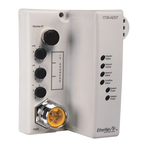
Page 86: Interpret The Status Indicators
Chapter Troubleshoot the Adapter This chapter describes the different status indicators available in the 1738 ArmorPOINT I/O EtherNet/IP adapter and how to interpret these indicators to help troubleshoot the module. The following table lists where to find specific information Topic Page Interpret the Status Indicators Status Indicators for ArmorPOINT I/O Adapters... -
Page 90: General Specifications
Appendix Specifications General Specifications The 1738-AENT/B adapters have the following general specifications. General Specifications Attributes Description Expansion I/O capacity, max 63 modules 5 rack-optimized connections (for digital modules only) 31 direct connections 1738-AENT/B backplane current output = 1.0 A. Actual number of modules can vary. Add up current requirements of modules you want to use to make sure they do not exceed the amperage limit of 1.0 A for the 1738-AENT/B adapter. -
Page 91: Power Supply
General Specifications Attributes Description Status indicators 3 red/green status indicators on CPU: Adapter Status Network Status POINTBus Status 1 green status indicator on CPU: Network Activity 2 green power supply status indicators on DC-DC Converter: System Power (5V DC to POINTBus Out) Adapter Power (24V DC from Field In) Power consumption, max 8.1 W @ 28.8V DC... -
Page 92: Ethernet Communication
Power Supply Specifications Attributes Description POINTBus output current, max 5V DC @ 1.0A Auxiliary power cable Standard cordset (single-ended), for example Allen-Bradley part number 889N-F4AFC-6F or 889N-R4AFC-6F. Standard patchcord (double-ended), for example, Allen-Bradley part number 889N-F4AFNU-6F or 889N-F4AFNV-6F. Interruption Output voltage stays within specifications when input drops out for 10 ms @ 10V with max load (1) Refer to publication M117-CA001A-EN-P... -
Page 93: Certifications
Environmental Specifications Attributes Description Shock, nonoperating IEC60068-2-27 (Test Ea, Unpackaged Shock): 50 g Emissions CISPR 11: Class A ESD immunity IEC 61000-4-2: 6 kV contact discharges 8 kV air discharges Radiated RF immunity IEC 61000-4-3: 10V/m with 1 kHz sine-wave 80% AM from 80...2000 MHz 10V/m with 200 Hz 50% Pulse 100% AM @ 900 MHz 10V/m with 200 Hz 50% Pulse 100% AM @ 1890 MHz 10V/m with 1 kHz sine-wave 80% AM from 2000...2700 MHz... -
Page 94: Overview
Appendix Adapter Web Dialogs Overview The Web dialog of the I/O adapter offers extensive internal and network diagnostics. To view the Web dialogs, enter the IP address of the I/O adapters into your browser For Information About Page Work with the Home Page Work with the Diagnostics Pages Use the Diagnostic Overview Page Use the Network Settings Page... - Page 95 To display and work with the adapter diagnostics home page, follow these procedures. Make sure that your PC Internet LAN setting and your TCP/IP IMPORTANT settings are configured to access the subnet on which your adapter communicates. 1. From your web browser, enter the adapter IP address to see the Home page. Enter the adapter IP address to see the home page.
-
Page 96: Work With The Diagnostics
– Allen-Bradley logo at the top of the page – Visit for additional information statement under Resources ab.com • Click Rockwell Automation at the top right to go to www.rockwellautomation.com. • Click the following to see additional diagnostics web pages. – Diagnostics - Diagnostic overview, Network Settings, Ethernet Statistics, I/O Connections, Advanced Diagnostics –... - Page 97 To use the Diagnostic Overview page for general diagnostics information, follow this procedure. 1. Click Diagnostic Overview from the tab at the top of the page or panel on the left. The Diagnostic Overview page opens. Download EDS files for your adapter 2.
-
Page 98: Use The Network Settings Page
– Current CIP I/O Connections – CIP I/O Connection Limit – Max I/O Connections Observed – Conn Opens – Open Errors – Conn Closes – Close Errors – Conn Timeouts • LED Status – Module Status – Network Status – Pointbus Status •... -
Page 99: Use The Ethernet Statistics Page
• Network Interface – Ethernet Address (MAC) – IP Address – Subnet Mask – Default Gateway – Primary Name Server – Secondary Name Server – Default Domain Name – Host Name – Name Resolution • Ethernet Interface Configuration – How the Network Configuration was obtained - Static or Dynamic •... - Page 100 The Ethernet Statistics page opens. 2. From the Ethernet Statistics page, view the following: • Refresh Rate (sec) • Ethernet Link – Interface State, Link Status, Media Speed, Duplex, Autonegotiate Status • Interface Counters – In Octets, In UCast Packets, In NUcast Packets, In Discards, In Errors, In Unknown Protos, Out Octets, Out Ucast Packets, Out NUcast Packets, Out Discards, Out Errors...
- Page 101 To use the I/O Connections page for CIP I/O (Class 1) connection information, follow this procedure. 1. Click I/O Connections from the tab at the top of the page or panel on the left. The I/O Connections page opens. The top value in this column representing Lost shows the number of packets from the missing source.
- Page 102 To use the Advanced Diagnostics page to review message services, use this procedure. 1. Click Advanced Diagnostics from the tab at the top of the page or panel on the left. The Advanced Diagnostics page opens. 2. From the Advanced Diagnostics page, select Backplane Statistics to see values similar to those shown.
-
Page 103: Work With The Configuration
3. From the Advanced Diagnostics page, select Module Statistics to see values similar to those shown. Work with the To work with the Configuration pages, follow these procedures. Configuration Pages The values on these pages are in non-volatile memory. Changes to IMPORTANT these parameters do not take effect until you reset or cycle power through the I/O adapters. - Page 104 1. From the Home page, click Configuration or Expand to see the Configuration options, if needed. 2. From the Configuration page, click one of the following: • Identity • Network • Services A login dialog opens as shown. The dialog may vary in appearance depending on your operating system and browser.
- Page 105 To use the Identity page to make entries for the host name, module description, module location, and chassis size, use this procedure. 1. Click Identity from the tab at the top of the page or panel on the left. The Identity page opens 2.
- Page 106 To use the Network Configuration page to make entries for enabling or disabling DHCP and setting TCP/IP parameters and Ethernet link operation, follow this procedure. 1. Click Network from the tab at the top of the page or panel on the left. The Network Configuration page opens.
-
Page 107: Use The Services Page
– Secondary Name Server – Domain Name • For Ethernet Link, select from these choices: – Autonegotiate Status - Autonegotiate Speed and Duplex - Force Speed and Duplex – Select Port Speed - 10 megabits, 100 megabits – Select Duplex Mode - Half Duplex, Full Duplex 4. -
Page 108: Work With The Browse Chassis Page
3. Click Apply Changes. Work with the Browse Use the Browse Chassis page for the following: • See what modules are present on the system. Chassis Page • Run a query from slot 1 to slot 63. • Display the modules found based on the query. •... - Page 109 After completing a query, here is how a typical Browse Chassis page looks. If there is no response to the query, the Module not found message appears. 3. To view information about a particular module, click the corresponding Module Description hyperlink. In the following example, the first Module has been selected: The 1738 Module Information page opens showing this information about the module:...
-
Page 110: Overview
Appendix Configure the RSLinx Ethernet Communication Driver Overview To communicate with your adapter over your network, you must configure the RSLinx Ethernet Communication Driver (AB_ETH) or the EtherNet/IP driver (AB-ETHIP). You can configure the AB_ETH driver with the IP addresses of all the Ethernet devices on your system. - Page 111 To configure the AB-ETH Ethernet communication driver perform the following steps: 1. Start the RSLinx software. 2. From the Communications menu, select Configure Drivers. 3. Select Ethernet Devices from the list and click Add/New... 4. Select the default driver name (for example, AB_ETH-1) or type in a name and click OK.
- Page 112 5. Click Add New and enter the IP address or Host Name of your Ethernet device (for example, 10.88.70.4, Pump1). 6. Repeat step 6 for each additional Ethernet device you need to access. 7. After entering the IP addresses, click Apply. 8.
- Page 113 To configure the AB-ETHIP Ethernet communication driver, perform the following steps. 1. Start the RSLinx software. 2. From the Communications menu, select Configure Drivers. 3. Select EtherNet/IP Devices from the list and click Add/New...
- Page 114 The Configure Driver dialog box opens. Make sure the Browse Local Subnet button is selected. The RSLinx software browses your local subnet and automatically reads the IP address. 4. Click OK. The AB-ETHIP driver is now configured and appears in the configured drivers window.
- Page 116 Index D H C P Numerics ( D y n a m i c H o s t C o n f i g u r a t i o n P r o t o c o l ) 1738-AENT 67, 69 specifications...
- Page 117 I P n e t w o r k F i e l d s i d e p o w e r s p l i t t i n g s u b g r o u p f i r m w a r e s u b n e t r e v is i o n s...
- Page 118 e m i s s i o n s E S D i m m u n i t y s p e c i f i c a t i o n s g e n e r a l s t a t i s t i c s P O I N T B u s o u t p u t c u r r e n t E t h e r n e t...
- Page 121 Rockwell Automation representative. New Product Satisfaction Return Rockwell Automation tests all of its products to ensure that they are fully operational when shipped from the manufacturing facility. However, if your product is not functioning and needs to be returned, follow these procedures.
Need help?
Do you have a question about the A Series and is the answer not in the manual?
Questions and answers