
Related Manuals for Rockwell Automation Allen-Bradley 1794-AENTR


Summary of Contents for Rockwell Automation Allen-Bradley 1794-AENTR
- Page 1 User Manual FLEX I/O Dual Port EtherNet/IP Adapter Modules Catalog Numbers 1794-AENTR, 1794-AENTRXT...
- Page 2 In no event will Rockwell Automation, Inc. be responsible or liable for indirect or consequential damages resulting from the use or application of this equipment.
- Page 3 Preface Read this preface to familiarize yourself with the rest of the manual. It provides information concerning: • who should use this manual • the purpose of this manual • related documentation • conventions used in this manual Who Should Use this This manual is intended for control engineers and technicians who are installing, configuring, and maintaining a redundant EtherNet/IP control system that Manual...
- Page 4 Information on how to install, configure and maintain linear and Device-level Guide, publication ENET-AP005 Ring (DLR) networks using Rockwell Automation EtherNet/IP devices with embedded switch technology. EtherNet/IP Modules in Logix5000 Control Systems User Detailed information on how to use EtherNet/IP modules with Logix5000...
-
Page 5: Table Of Contents
Table of Contents Preface Who Should Use this Manual ........iii Purpose of this Manual . - Page 6 Chapter 4 Rack Optimized Discrete I/O Overview ............23 Set Up the Hardware .
- Page 7 Use the Ethernet Statistics Page ....... . 62 Use the I/O Connections Page....... . . 63 Work with the Configuration Pages .
- Page 8 viii Publication 1794-UM066B-EN-E - March 2015...
-
Page 9: Overview
Chapter Overview of FLEX I/O and Your Redundant EtherNet/IP Adapter Module Overview This chapter provides a description of the FLEX I/O dual port EtherNet/IP adapter modules and an overview of how they communicate with programmable controllers. Topic Page The FLEX I/O System Adapter Features Types of Adapters Hardware and Software Compatibility... -
Page 10: Adapter Features
Overview of FLEX I/O and Your Redundant EtherNet/IP Adapter Module The FLEX system consists of an adapter module, terminal base unit, DIN rail, power supply, and adapter cabling components. You can use up to 8 terminal bases per adapter module. For detailed instructions on how to set up and install your module, refer to the topic, Install Your FLEX I/O Adapter on page 7. -
Page 11: What The Adapter Does
Overview of FLEX I/O and Your Redundant EtherNet/IP Adapter Module Refer to the 1794 FLEX I/O Communication Adapters Specifications Technical Data Sheet, publication 1794-TD014, for technical specifications and certifications for your adapter. What the Adapter Does The 1794-AENTR and 1794-AENTRXT adapters perform two primary tasks: •... -
Page 12: Specifying The Requested Packet Interval (Rpi)
Overview of FLEX I/O and Your Redundant EtherNet/IP Adapter Module (multicast) their data either upon a change of state (COS) or periodically. The frequency of update depends upon the options chosen during configuration and where on the network the input module resides. The input module, therefore, is a producer of input data and the controller is a consumer of the data. -
Page 13: Mixing Rack Optimized And Direct Connections
Overview of FLEX I/O and Your Redundant EtherNet/IP Adapter Module the 8 I/O modules. If you use a rack-optimized connection to transfer the data, you only need a single connection – the connection to the adapter. Although rack optimized connections offer an efficient way to use IMPORTANT resources, there are a few limitations on their use: •... - Page 14 Overview of FLEX I/O and Your Redundant EtherNet/IP Adapter Module Notes: Publication 1794-UM066B-EN-E - March 2015...
-
Page 15: Overview
Chapter Install Your FLEX I/O Adapter Overview This chapter describes how to physically install the 1794-AENTR or 1794-AENTRXT adapter on the DIN rail and connect it to the EtherNet/IP network. The following table lists where to find specific information. Topic Page Module Components Mount Your Adapter on a DIN Rail... -
Page 16: Mount Your Adapter On A Din Rail
Install Your FLEX I/O Adapter Mount Your Adapter on a Follow these steps to mount the adapter on a new system before installing any I/O modules. DIN Rail 45822 ATTENTION: During mounting of all devices, be sure that all debris (for example, metal chips, wire strands) is kept from falling into the module. -
Page 17: Mount On A Panel Or Wall
Install Your FLEX I/O Adapter Mount on a Panel or Wall If mounting this adapter to a panel or wall, refer to publication 1794-TD013, Panel Mounting Kit, Cat. No. 1794-NM1. ATTENTION: If you insert or remove the module while backplane power is on, an electrical arc can occur. - Page 18 Install Your FLEX I/O Adapter terminal base and the adapter tight together, reducing the possibility of a break in communication over the backplane. 7. Complete the adapter mounting as shown below. Push down and in at the same time to lock the adapter to the DIN rail. If the adapter does not lock in place, use a screwdriver or similar device to move the locking tab down while pressing the adapter flush onto the DIN rail, and release the locking tab to lock the adapter module in place.
-
Page 19: Connect Wiring
Install Your FLEX I/O Adapter Connect Wiring 45823 WARNING: If you connect or disconnect wiring while the field-side power is on, an electrical arc can occur. This could cause an explosion in hazardous location installations. Be sure that power is removed or the area is nonhazardous before proceeding. 1. -
Page 20: Set The Network Address
• Use the thumbwheel switches on the module. • Use a Dynamic Host Configuration Protocol (DHCP) server, such as Rockwell Automation DHCP. • Retrieve the IP address (if previously set) from nonvolatile memory. The adapter reads the thumbwheel switches first to determine if the switches are set to a valid number. -
Page 21: Mounting Dimensions
Install Your FLEX I/O Adapter Mounting Dimensions The module has the following mounting dimensions. 1794-AENTR shown (1.96) 80.4 (3.16) 87.4 (3.44) 30.4 (1.19) (3.70) 45826 Millimeters 1794-AENTR, 1794-AENTRXT (Inches) 87.4 H x 94W x 92D (344H x 3.7W x 3.6D) Publication 1794-UM066B-EN-E - March 2015... - Page 22 Install Your FLEX I/O Adapter Notes: Publication 1794-UM066B-EN-E - March 2015...
-
Page 23: Overview
Chapter Configure the Adapter for Your EtherNet/IP Network Overview This chapter describes how to configure the 1794-AENTR or 1794-AENTRXT adapter module for the ControlLogix system. Topic Page Configuration Requirements IP Address Gateway Address Subnet Mask Use the Rockwell BootP/DHCP Utility Configure Your Adapter using DHCP Software Configuration Before you can use your 1794-AENTR or 1794-AENTRXT adapter, you must... -
Page 24: Gateway Address
Configure the Adapter for Your EtherNet/IP Network The IP address is 32 bits long and has a Net ID part and a Host ID part. Networks are classified A, B, C, (or other). The class of the network determines how an IP address is formatted. Host ID Class A Net ID... -
Page 25: Subnet Mask
Configure the Adapter for Your EtherNet/IP Network networks. The following figure shows gateway G connecting Network 1 with Network 2. 128.1.0.1 Network 1 128.1.0.2 128.2.0.3 128.2.0.2 128.2.0.1 Network 2 When host B with IP address 128.2.0.1 communicates with host C, it knows from C’s IP address that C is on the same network. -
Page 26: Use The Rockwell Bootp/Dhcp Utility
Configure the Adapter for Your EtherNet/IP Network Two bits of the Class B host ID have been used to extend the net ID. Each unique combination of bits in the part of the Host ID where subnet mask bits are 1 specifies a different logical network. - Page 27 Configure the Adapter for Your EtherNet/IP Network The BOOTP/DHCP Request History dialog appears showing the hardware addresses of devices issuing BootP/DHCP requests. 2. Double-click the hardware address of the device you want to configure. The New Entry dialog appears showing the device’s Ethernet Address (MAC).
- Page 28 Configure the Adapter for Your EtherNet/IP Network The device is added to the Relation List, displaying the Ethernet Address (MAC) and corresponding IP Address, Hostname and Description (if applicable). When the IP address assignment is made, the address displays in the IP Address column in the Request History section.
-
Page 29: Save The Relation List
Configure the Adapter for Your EtherNet/IP Network Save the Relation List You can save the Relation List to use later. To save the Relation List do the following: 1. Select Save As... from the File menu. The Save As dialog box appears. 2. -
Page 30: Chapter Summary
Configure the Adapter for Your EtherNet/IP Network dynamic allocation of network addresses and configurations to newly attached devices. Be cautious about using DHCP software to configure your adapter. A BootP client, such as the 1794-AENTR or 1794-AENTRXT adapter, can boot from a DHCP server only if the DHCP server is specifically written to also handle BootP queries. -
Page 31: Overview
Chapter Rack Optimized Discrete I/O Overview In this example a ControlLogix processor communicates with FLEX I/O via the 1794-AENTR adapter using a rack optimized connection. The processor reads data from all digital input modules and sends data to all digital output modules configured in a rack connection simultaneously. -
Page 32: Create The Example Application
Rack Optimized Discrete I/O 1794-AENTR SLOT FLEX I/O 130.130.130.3 SLOT Local Data chassis 1756-EN2TR Logix5572c 1794-OB16 130.130.130.2 ontroller digital output 1794-IB16 digital input 130.130.130.1 Programming terminal To work along with this example set up your system as shown above. • Note that in the example application, the Logix5572 controller and 1756-EN2TR module are assumed to be in the slots shown above. - Page 33 Rack Optimized Discrete I/O 1. Start the RSLogix 5000 Enterprise Series software. The RSLogix 5000 main dialog opens. 2. From the File menu, select New. The New Controller dialog opens. 3. Enter an appropriate Name for the Controller, for example: FLEX_IO_Controller.
-
Page 34: Configure The I/O
Rack Optimized Discrete I/O Configure the I/O Setting up a sample I/O Configuration project involves the following: • Adding the local 1756-EN2TR module to the I/O configuration. • Adding the 1794-AENTR adapter as a child of the 1756-EN2TR module. • Adding the I/O modules as children of the adapter. Click the Help button on the configuration dialogs shown in this IMPORTANT section if you need assistance in selecting and setting the... -
Page 35: Add The Flex I/O Adapter To The I/O Configuration
Rack Optimized Discrete I/O 3. Select the 1756-EN2TR EtherNet/IP Bridge, and then click Create. The New Module dialog opens. 4. Configure your 1756-EN2TR EtherNet/IP Bridge module through the different tabs available. Enter values for Name, IP Address, Slot, Electronic Keying, and Revision, as follows: Name EN2TR... - Page 36 Rack Optimized Discrete I/O 1. In the Project dialog, right-click the local 1756-EN2TR module under the I/O Configuration folder, and then select New Module. The Select Module Type dialog opens. 2. Select the 1794-AENTR Ethernet adapter from the list and click Create. The Module Properties dialog opens.
-
Page 37: Add The Flex I/O Modules To The I/O Configuration
Rack Optimized Discrete I/O Comm Format Rack Optimization Chassis Size 8 (default) Electronic Keying Compatible Module 5. If you need to change the values, click Change... The Module Definition dialog opens. 6. Click OK to accept the configuration. The 1794-AENTR adapter appears indented under the local 1794-ENBT in the I/O Configuration folder. -
Page 38: Add The Digital Input Module
Rack Optimized Discrete I/O Add the Digital Input Module 1. Under the I/O Configuration folder, right-click the remote 1794-AENTR adapter, and then select New Module. The Select Module Type window opens. 2. Select the 1794-IB16 module from the list, and then click Create. The New Module dialog opens. -
Page 39: Add The Digital Output Module
Rack Optimized Discrete I/O 3. Enter the following parameters: Name FLEX_Digital_Input Slot Comm Format Rack Optimization Electronic Keying Compatible Module 4. Click OK to save the configuration. The digital input module appears in the I/O configuration indented under the 1794-AENTR adapter. Add the Digital Output Module 1. - Page 40 Rack Optimized Discrete I/O The Select Module Type window opens. 2. Select the 1794-OB16 module from the list, and then click Create. The New Module dialog opens. 3. Enter the following parameters: Name FLEX_Digital_Output Slot Comm Format Rack Optimization Electronic Keying Compatible Module Publication 1794-UM066B-EN-E - March 2015...
-
Page 41: Edit The Controller Tags
Rack Optimized Discrete I/O 4. Click OK to save the configuration. The digital input module appears in the I/O configuration indented under the 1794-AENTR adapter. Edit the Controller Tags When you add modules to the I/O configuration the system creates tags for those modules to use in the application program. -
Page 42: Create The Ladder Program
Rack Optimized Discrete I/O Create the Ladder Program Next, create the example ladder program to test the I/O. 1. Double-click Main Routine under the Main Program folder, and then enter the following ladder program, using the tag previously created. 2. Save the program. Download the Program to the Controller To download the program to the controller do the following: Publication 1794-UM066B-EN-E - March 2015... -
Page 43: Test The Example Application
Rack Optimized Discrete I/O 1. Click on the Communications menu and select Who Active. The Who Active window opens . 2. Select your Ethernet driver (for example, AB_ETH-1) and expand the tree through the backplane of the local ControlLogix chassis. 3. -
Page 44: Chapter Summary
Rack Optimized Discrete I/O 1. Remove power from the FLEX I/O and wire inputs 0 and 2 of the 1794-IB16 FLEX I/O input module as shown in the following figure: Reset Count 1794-IB16 16 (COM) 2. Restore power to the FLEX I/O. 3. -
Page 45: Overview
Chapter Analog I/O with Direct Connection Overview In this example you add analog input and output modules to the FLEX I/O configured with two digital I/O modules in the previous chapter. Analog modules default to direct connection, so you will open a direct connection to each analog module while still using a single rack optimized connection for the two digital I/O modules. -
Page 46: Create The Example Application
Analog I/O with Direct Connection 1794-AENTR SLOT FLEX I/O 130.130.130.3 SLOT Local Data Chassis 1794-OF4I 1794-OB16 1756-EN2TR Logix5572 Analog Digital Output 130.130.130.2 Controller Output 1794-IB16 Digital Input 1794-IF4I Analog Input 130.130.130.1 Programming terminal • Note that in the example application, the Logix5572 controller and 1756-EN2TR module are in the slots shown above in the ControlLogix chassis. -
Page 47: Add The Analog Modules To The I/O Configuration
Analog I/O with Direct Connection 2. Open the project file from the previous chapter (for example, FLEX_IO_Controller). 3. Save the file using a different name (for example, FLEX_IO_Controller_2). Add the Analog Modules to You must now add the analog I/O modules to the I/O Configuration. In this example, you add a 1794-IF4I analog input module and a 1794-OF4I analog the I/O Configuration output module. - Page 48 Analog I/O with Direct Connection 1. Right click the 1794-AENTR adapter under the I/O Configuration folder, and then select New Module. The Select Module Type window opens. 2. Select the 1794-IF4I/A analog input module from the list, and then click Create. The New Module dialog opens.
- Page 49 Analog I/O with Direct Connection 5. On the Connection tab, adjust the Requested Packet Interval (RPI) to meet your system requirements. For this example you can leave it at the default 50 ms rate. This RPI is used for the direct connection to this analog module. The two rack connected digital I/O modules continue to communicate at the RPI of the rack connection.
-
Page 50: Add The Analog Output Module To The I/O Configuration
Analog I/O with Direct Connection 8. Click Apply to save the configuration, and then OK to close the dialog. The analog input module appears in the I/O configuration indented under the 1794-AENTR adapter. Add the Analog Output Module to the I/O Configuration 1. - Page 51 Analog I/O with Direct Connection The Select Module Type window opens. 2. Select the 1794-OF4I module from the list, and then click Create. The New Module dialog opens. 3. Enter the following parameters: Name FLEX_Analog_Output Slot Comm Format Output Data Electronic Keying Compatible Module All analog Comm Formats use direct connection.
- Page 52 Analog I/O with Direct Connection 5. On the Connection tab, adjust the Requested Packet Interval (RPI) to meet your system requirements. For this example change the RPI to 50 ms rate. This RPI is used for the direct connection to this analog module. The two rack connected digital I/O modules continue to communicate at the RPI of the rack connection.
-
Page 53: Edit The Controller Tags
Analog I/O with Direct Connection 8. On the Configuration tab, use the pull-down list to set the Voltage/Current Range for Channel 0 to 0 to 10V – Binary to match the input configuration of the 1794-IF4I module. Leave the other channels at their default values. 9. - Page 54 Analog I/O with Direct Connection 1. Double-click the Controller Tags folder in the project window. Note that new tags have been added for the analog I/O modules. New tags created by the system for the analog modules Make sure you select the Edit Tags tab at the bottom of the Controller Tags window, and then create the following tag: Type Analog_Test_Signal...
-
Page 55: Modify The Ladder Program
Analog I/O with Direct Connection Modify the Ladder Program Make the following change to the ladder program to test the new configuration. 2. Double-click Main Routine under the Main Program folder, and then add rungs 3 and 4 to the ladder program. 3. -
Page 56: Test The Example Application
Analog I/O with Direct Connection 2. Select your Ethernet driver (for example, AB_ETH-1) and expand the tree through the backplane of the local ControlLogix chassis. 3. Highlight the controller. and then click Download to download the program to the Logix5572 controller. A Download dialog appears: 4. -
Page 57: Chapter Summary
Analog I/O with Direct Connection 4. Monitor channel 0 of the 1794-IF4I input module (FLEX_IO_Adapter:2.I.Ch0Data above). The value slowly rises to approximately 32000, resets to zero, starts rising again, and so on, as the output of the timer is received from the 1794-OF4I output module. - Page 58 Analog I/O with Direct Connection Notes: Publication 1794-UM066B-EN-E - March 2015...
-
Page 59: Overview
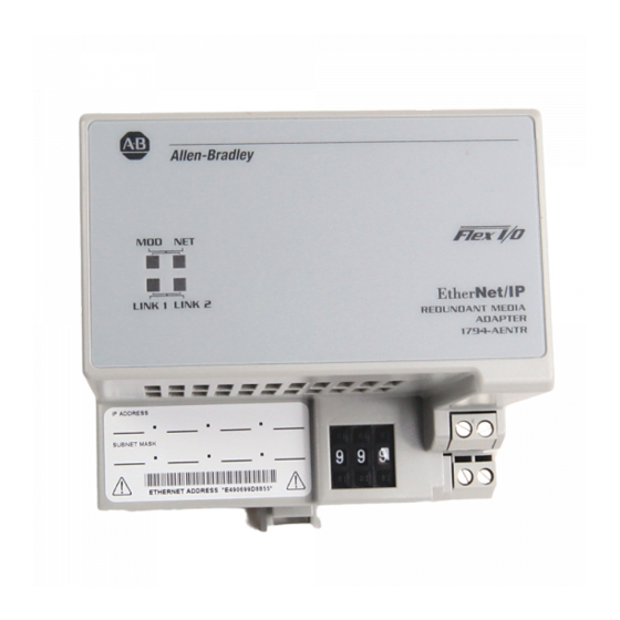
Appendix Interpret Status Indicators Overview The faceplates of the 1794-AENT and 1794-AENTRXT adapters are provided with status indicators that display the Module Status, Network Status, and Link Status for both links. Status Indicators 1794-AENTR, 1794-AENTRXT Module 1794-AENTR shown Network status Module status Link 1 status Link 2 status... -
Page 60: Chapter Summary
Interpret Status Indicators Status Indicator Identification Indicator State Status Module Status Indicator No power. Adapter does not have 24V DC power. Make sure power is being supplied to the adapter. Flashing green Standby. Adapter not configured. Configure adapter. Green Operational. Adapter operating correctly. No action required. -
Page 61: Overview
Appendix Configure the RSLinx Ethernet Communication Driver Overview Read this appendix to install, and configure the AB_ETH driver. For Information On Page About the Ethernet Communication Driver Install the RSLinx Software Configure the AB_ETH Driver About the Ethernet In order to communicate with your 1794-AENTR or 1794-AENTRXT adapters over your network you must configure the RSLinx Ethernet communication Communication Driver driver (AB_ETH). - Page 62 Configure the RSLinx Ethernet Communication Driver 1. Start RSLinx. 2. From the Communications menu, select Configure Drivers. 3. From the Available Driver Types drop down menu, select Ethernet Devices, and then click Add/New. The Add New RSLinx Driver dialog box appears. 4.
- Page 63 Configure the RSLinx Ethernet Communication Driver 7. When you are done entering the IP addresses, click Apply and then click OK to close the Configure driver window. The new driver appears in the list of configured drivers. Your list displays the drivers you have configured on your workstation.
- Page 64 Configure the RSLinx Ethernet Communication Driver Notes: Publication 1794-UM066B-EN-E - March 2015...
-
Page 65: Overview
Appendix Adapter Web Dialogs Overview The Web server dialog of the FLEX I/O adapter offers extensive internal and network diagnostics. To view the Web dialogs, enter the IP address of the FLEX I/O adapters into your browser. Topic Page Work with the Home Page Work with the Diagnostics Pages Use the Diagnostic Overview Page Use the Network Configuration Page... - Page 66 Allen-Bradley logo at the top of the page – AB.com link under Resources on the right hand side of the page • Click Rockwell Automation at the top right to go to www.rockwellautomation.com. • Click the following to see additional diagnostics web pages.
-
Page 67: Work With The Diagnostics
Adapter Web Dialogs Work with the Diagnostics To work with the Diagnostics options, follow these procedures. Pages 1. From the Home page, click Diagnostics or Expand to see the following diagnostics options from the panel at the left. • Diagnostic Overview •... -
Page 68: Use The Diagnostic Overview Page
Adapter Web Dialogs Use the Diagnostic Overview Page To use the Diagnostic Overview page for general diagnostics information, click Diagnostic Overview from the tab at the top of the page or panel on the left. From the Diagnostic Overview page, you can view the following: •... -
Page 69: Use The Network Settings Page
Adapter Web Dialogs Use the Network Settings Page To use the Network Settings page for network related information, click Network Settings tab at the top of the page or panel on the left. This opens the Network Settings page. From the Network Settings page, you can view the following: •... -
Page 70: Use The Ethernet Statistics Page
Adapter Web Dialogs Use the Ethernet Statistics Page To use the Ethernet Statistics page for information about the Ethernet link and interface and media counters, click Ethernet Statistics tab at the top of the page or from the panel on the left. The Ethernet Statistics page opens. -
Page 71: Use The I/O Connections Page
Adapter Web Dialogs – FCS Errors – Single Collisions – SQE Test Errors – Deferred Transmissions – Late Collisions – Excessive Collisions – MAC Transmit Errors – Carrier Sense Errors – Frame Too Long – MAC Receive Errors • Interface Counters –... -
Page 72: Work With The Configuration
Adapter Web Dialogs • Received / Transmitted packets • Connection ID • Source • Destination • Multicast Address • RPI • Lost Packets • Size Work with the To work with the Configuration pages, follow these procedures. Configuration Pages The values on these pages are in non-volatile memory. Changes to these IMPORTANT parameters do not take effect until you reset or cycle power through the FLEX I/O adapter. -
Page 73: Use The Device Identity Page
Adapter Web Dialogs A login dialog opens as shown. The dialog may vary in appearance depending on your operating system and browser. 3. From the user name and password dialog, enter values, noting the following: • The values for user name and password are case sensitive. •... -
Page 74: Use The Network Configuration Page
Adapter Web Dialogs The Identity page opens. From the Identity page, complete entries for the following, noting that the description and location help you identify where modules are in the facility: • Host Name • Module Description • Module Location 6. - Page 75 Adapter Web Dialogs The Network Configuration page opens. From the Network Configuration page, complete these entries, noting that values for Network Interface are disabled when DHCP is Dynamic DHCP and port speed and duplex mode are disabled when Autonegotiate Speed and Duplex is selected.
-
Page 76: Use The Device Services Page
Adapter Web Dialogs – Secondary Name Server – Domain Name • For Ethernet Link Port 1 and Port 2, specify the following: – Autonegotiate Status - Autonegotiate Speed and Duplex - Force Speed and Duplex – Select Port Speed – 10 megabits, 100 megabits –... - Page 77 Index Numerics adapter module 1 address 1756-EN2TR 24, 38 default 16 module 28, 38 ethernet 19 1756-EN2TR bridge 27 Ethernet hardware 15 1756-EN2TR module 24, 28, 38 gateway 12, 15, 16 1794-IB16 24 hardware 19 host ID 17 IP 2, 12, 15, 16, 53 MAC 17 AB_ETH 35, 38, 48, 53, 54 network 12, 18, 22...
- Page 78 Index gateway 18 module description 66 gateway address 15 module location 66 IP address 15 device services new adapter 15 enable 68 rack connection 23 new password 68 routing tables 3 DHCP 21 RPI 5 DHCP enabled 57 RSLinx 24, 38 diagnostic overview 59 subnet mask 15 diagnostics...
- Page 79 Index FLEX I/O 23 Internet Protocol adapter 1 IP 12 description 1 invalid number I/O module 1 thumbwheel switches 12 module components 7 system 1 Internet Protocol 12 terminal base 1 IP Address 19, 27 FLEX I/O module 2, 29 IP address 2, 12, 15, 16, 17, 20, 53, 54, 57, 58 FLEX I/O system 1 adapter 22...
- Page 80 Index FLEX I/O 2, 29 node address 12 I/O 1, 3, 4, 5, 8, 26 set 12 input 3, 23, 29, 37 input, add 30 insert or remove 9 output data 43 latching mechanism 9 location 57 output module 23, 29 locking tab 7 overview name 57...
- Page 81 Index status indicators 7, 51 unique subnet mask 48-bit hardware address 15 combination of bits 18 configure 15 IP address 15, 52 switches unique IP address 15 IP address 7 thumbwheel 12 web dialogs TCP/IP CIP connection statistics 60 configuration 64 network 21 diagnostic overview 59, 60 protocol iii...
- Page 82 Index Publication 1794-UM066B-EN-E - March 2015...
- Page 83 Rockwell Automation Publication 1794-UM066B-EN-E - March 2015...
- Page 84 Rockwell Automation representative. New Product Satisfaction Return Rockwell Automation tests all of its products to ensure that they are fully operational when shipped from the manufacturing facility. However, if your product is not functioning and needs to be returned, follow these procedures.
Need help?
Do you have a question about the Allen-Bradley 1794-AENTR and is the answer not in the manual?
Questions and answers