Rohde & Schwarz NGA100 Series Getting Started
Hide thumbs
Also See for NGA100 Series:
- User manual (125 pages) ,
- User manual (164 pages) ,
- Getting started (47 pages)

Subscribe to Our Youtube Channel
Related Manuals for Rohde & Schwarz NGA100 Series


Summary of Contents for Rohde & Schwarz NGA100 Series
- Page 1 ® R&S NGA100 Power Supply Series Getting Started (Æ1ç22) 5601890202 Version 03 Distributed by: Sie haben Fragen oder wünschen eine Beratung? Angebotsanfrage unter 07121 / 51 50 50 oder über info@datatec.de...
- Page 2 ® This manual describes the following R&S NGA100 models with firmware version 1.00 and higher: ● R&S ® NGA101 One-Channel 35V/6A Power Supply 40 W (5601.8002.02) ● R&S ® NGA102 Two-Channel 35V/6A Power Supply 80 W (5601.8002.04) ● R&S ® NGA141 One-Channel 100V/2A Power Supply 40 W (5601.8002.03) ●...
- Page 3 Safety Instructions Instrucciones de seguridad Sicherheitshinweise Consignes de sécurité Risk of injury and instrument damage The instrument must be used in an appropriate manner to prevent electric shock, fire, personal injury or instrument damage. ● Do not open the instrument casing. ●...
- Page 4 Gefahr von Verletzungen und Schäden am Gerät Betreiben Sie das Gerät immer ordnungsgemäß, um elektrischen Schlag, Brand, Verletzungen von Personen oder Geräteschäden zu verhindern. ● Öffnen Sie das Gerätegehäuse nicht. ● Lesen und beachten Sie die "Grundlegenden Sicherheitshinweise", die als gedruckte Broschüre dem Gerät beiliegen.
- Page 5 이 기기는 업무용(A급) 전자파 적합기기로서 판매자 또는 사용자는 이 점을 주의하시기 바라며, 가정외의 지역에서 사용하는 것을 목적으로 합니다.
-
Page 6: Table Of Contents
® Contents R&S NGA100 Contents 1 Documentation Overview............5 1.1 Manuals....................5 1.2 Data Sheet..................... 5 1.3 Calibration Certificate................6 1.4 Release Notes, Open Source Acknowledgment........ 6 2 Welcome to R&S NGA100............. 7 3 Putting into Operation............8 3.1 Safety..................... 9 3.2 Intended Operation................11 3.3 Unpacking and Checking the Instrument......... - Page 7 ® Contents R&S NGA100 Getting Started 5601.8902.02 ─ 03...
-
Page 8: Documentation Overview
® Documentation Overview R&S NGA100 Data Sheet Documentation Overview This section provides an overview of the R&S NGA100 user documentation. Manuals You find the documents on the R&S NGA100 product page at: www.rohde-schwarz.com/manual/nga100 Getting Started Introduces the R&S NGA100 power supply series and describes how to set up and start working with the instrument. -
Page 9: Calibration Certificate
® Documentation Overview R&S NGA100 Release Notes, Open Source Acknowledgment www.rohde-schwarz.com/brochure-datasheet/nga100 Calibration Certificate The document is available on https://gloris.rohde-schwarz.com/calcert. You need the device ID of your instrument, which you can find on a label on the rear panel. Release Notes, Open Source Acknowledgment The release notes list new features, improvements and known issues of the cur- rent firmware version, and describe the firmware installation. -
Page 10: Welcome To R&S Nga100
® Welcome to R&S NGA100 R&S NGA100 Welcome to R&S NGA100 The one-channel or two-channel power supply series are based on a classical transformer concept with high efficiency electronic pre-regulators and secondary linear regulators. This concept allows the instrument to achieve the high output power within a minimum space, high efficiency and lowest residual ripple. -
Page 11: Putting Into Operation
® Putting into Operation R&S NGA100 Putting into Operation This chapter describes the steps to set up the R&S NGA100 for the first time. Risk of injury and instrument damage The instrument must be used in an appropriate manner to prevent electric shock, fire, personal injury, or damage. -
Page 12: Safety
® Putting into Operation R&S NGA100 Safety Risk of radio interference This is a class A product. In a domestic environment, this product may cause radio interference in which case the user may be required to take adequate measures. EMI impact on measurement results Electromagnetic interference (EMI) may affect the measurement results. - Page 13 ® Putting into Operation R&S NGA100 Safety compliance with the regulations of the European standard EN 61010-1 and the international standard IEC 61010-1. To maintain this condition and ensure safe operation, you must observe all instructions and warnings given in this user manual. Casing, chassis and all mea- suring ports are connected to a protective earth conductor.
-
Page 14: Intended Operation
® Putting into Operation R&S NGA100 Intended Operation Exceeding the low voltage protection Use insulated wires and not bare wires for the terminal connection. For the series connection of all output voltages of the 35 V variant, it is pos- sible to exceed the low voltage protection of 42 V. -
Page 15: Unpacking And Checking The Instrument
® Putting into Operation R&S NGA100 Unpacking and Checking the Instrument The instrument is designed for use in the following sectors: Industrial, residential, business and commercial areas and small businesses. The instrument is designed for indoor use only. Before each measurement, you need to verify at a known source if the instrument functions properly. - Page 16 ® Putting into Operation R&S NGA100 Unpacking and Checking the Instrument parts. If there is any damage, immediately contact the carrier who delivered the instrument. Packing material Retain the original packing material. If the instrument needs to be transpor- ted or shipped at a later date, you can use the material to protect the control elements and connectors.
-
Page 17: Setting Up The Instrument
® Putting into Operation R&S NGA100 Setting Up the Instrument Setting Up the Instrument The R&S NGA100 is designed for benchtop and rackmount. 3.4.1 Bench Operation On a benchtop, the R&S NGA100 can either lie flat or stand on its feet. The feet on the bottom can be folded out to set the instrument in an inclined position. -
Page 18: Instrument Tour
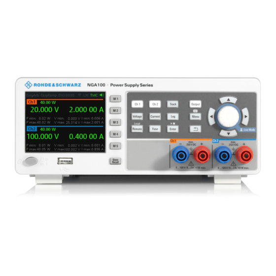
® Instrument Tour R&S NGA100 Overview of Controls Instrument Tour This chapter provides an overview of all the controls available in the R&S NGA100 models and steps to switch on the instrument for the first time. ● Overview of Controls..................15 ●... - Page 19 ® Instrument Tour R&S NGA100 Overview of Controls Figure 4-1: Front panel of R&S NGA100 with 2 channels 1 = Display 2 = Function keys 3 = Rotary knob and arrow keys 4 = Output channels (see Table 4-1) 5 = USB connector 6 = Power key Display (1) The display is a color LCD screen.
- Page 20 ® Instrument Tour R&S NGA100 Overview of Controls Rotary knob and arrow keys (3) Rotary knob and arrow keys are means of navigation and adjustment. When pressed or rotated, they perform tasks like navigation around the screen, adjust- ment of parameter values or confirmation of entries. For detailed description on rotary knob and arrow keys, see section "Navigation Controls"...
- Page 21 ® Instrument Tour R&S NGA100 Overview of Controls Figure 4-2: Rear panel of R&S NGA100 7 = AC inlet with fuse holder 8 = Ethernet (LAN) connector 9 = USB connector 10 = Digital I/O connector 11 = Rear panel connector AC inlet with fuse holder (7) Main supply cord Do not use detachable mains supply cord with inadequate rating.
- Page 22 ® Instrument Tour R&S NGA100 Overview of Controls USB connector (9) The USB connector is a Type-B connector for remote control operation via USB TMC or USB VCP. Digital I/O connector (10) The Digital I/O connector is a 5-pin terminal block for external trigger input or out- put.
-
Page 23: Switching On The Instrument
® Instrument Tour R&S NGA100 Switching On the Instrument 4.1.3 Bottom Panel The voltage selector is located at the bottom panel. On your first power-on con- nection, you should see a yellow label sticker attached over the inlet. Before peeling off the yellow label sticker, make sure that the correct fuse rating is used for the mains voltage. - Page 24 ® Instrument Tour R&S NGA100 Switching On the Instrument To change the power fuse / mains voltage setting: 1. Peel off the yellow label sticker on the AC inlet. 2. Pull out the fuse holder which is located directly on top of the socket. 3.
-
Page 25: Trying Out The Instrument
® Trying Out the Instrument R&S NGA100 Setting the Output Voltage and Current Limit Trying Out the Instrument This chapter describes some basic functions that you can perform with the R&S NGA100. Selecting the Channels To select a channel, press the corresponding channel key. The key illuminates. Setting the Output Voltage and Current Limit To set the output voltage and current limit via Live-Mode: 1. -
Page 26: Activating The Channels Output
® Trying Out the Instrument R&S NGA100 Storing/Recalling of Instrument Settings Activating the Channels Output The output voltages can be switched on or off regardless of the operating mode of the instrument. To activate the channel output, press the [Output] key on the front panel followed by the desired channel key or vice versa. -
Page 27: Maintenance And Support
® Maintenance and Support R&S NGA100 Contacting Customer Support Maintenance and Support Maintenance Regular maintenance improves the life span of the instrument, the following chap- ter provides information on instrument maintenance. Cleaning Before cleaning the instrument, ensure that it has been switched off and the power cable is disconnected. - Page 28 ® Maintenance and Support R&S NGA100 Contacting Customer Support Contact information Contact our customer support center at www.rohde-schwarz.com/support, or fol- low this QR code: Figure 6-1: QR code to the Rohde & Schwarz support page Getting Started 5601.8902.02 ─ 03...
-
Page 29: Index
® Index R&S NGA100 Index Setting up the instrument Bench operation ........14 Bottom panel Rack mounting ........14 Voltage selector ........20 Switching off the instrument ....20 Voltage selector label ......20 Switching on the instrument ....20 Calibration certificate ......... 6 Trying out the instrument Controls ...........
Need help?
Do you have a question about the NGA100 Series and is the answer not in the manual?
Questions and answers