Rohde & Schwarz NGP800 Series User Manual
Hide thumbs
Also See for NGP800 Series:
- User manual (201 pages) ,
- Getting started (57 pages) ,
- Manual (7 pages)
Table of Contents
Advertisement
Quick Links
Advertisement
Chapters
Table of Contents

Subscribe to Our Youtube Channel
Related Manuals for Rohde & Schwarz NGP800 Series


Summary of Contents for Rohde & Schwarz NGP800 Series
- Page 1 ® R&S NGP800 Power Supply Series User Manual (Æ1Æ:2) 5601561002 Version 11...
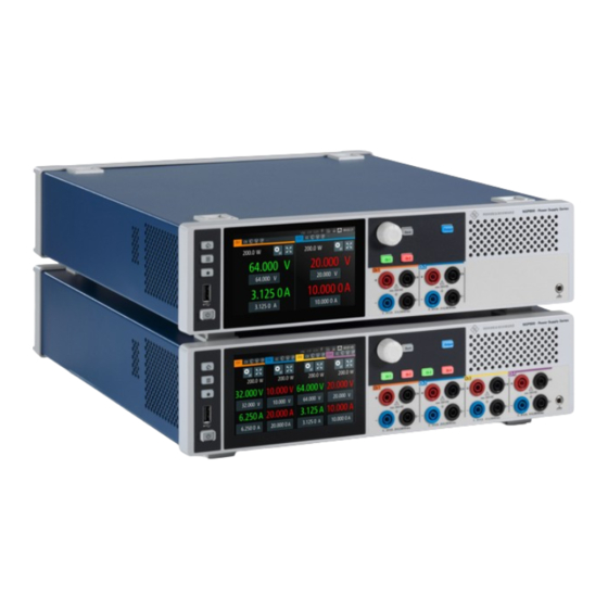
- Page 2 ® This manual describes the following R&S NGP800 models with firmware version 2.025 or higher: ● ® R&S NGP802 Two-channel 32V/20A Power Supply 400 W (5601.4007.05) ● ® R&S NGP822 Two-channel 64V/10A Power Supply 400 W (5601.4007.06) ● ® R&S NGP804 Four-channel 32V/20A Power Supply 800 W (5601.4007.02) ●...
-
Page 3: Table Of Contents
® Contents R&S NGP800 Contents 1 Safety and regulatory information............9 Safety instructions......................9 Labels on R&S NGP800....................12 Warning messages in the documentation..............13 Korea certification class A..................14 2 Documentation overview..............15 Manuals........................15 Data sheet........................15 Calibration certificate....................16 Release notes, open source acknowledgment (OSA)..........16 3 Conventions used in the documentation...........17 Typographical conventions..................17 Conventions for procedure descriptions..............17... - Page 4 ® Contents R&S NGP800 5.2.1 Front panel........................28 5.2.2 Rear panel........................30 Trying out the instrument...................33 5.3.1 Selecting the channels....................33 5.3.2 Setting the output voltage and current limit..............33 5.3.3 Activating the channels output..................35 5.3.4 Saving/Recalling of instrument settings................ 36 Instrument control......................
- Page 5 ® Contents R&S NGP800 Output setting......................67 7.3.1 Delay..........................68 7.3.2 Remote sensing......................70 7.3.3 High impedance mode....................71 7.3.4 Slew rate control......................71 Analog input........................ 72 Protection........................74 7.5.1 Overcurrent protection (OCP)..................74 7.5.2 Overvoltage protection (OVP)..................76 7.5.3 Overpower protection (OPP)..................77 7.5.4 Safety limits........................78 Tracking function......................
- Page 6 ® Contents R&S NGP800 7.17.2 Appearance settings....................127 7.17.3 Sound settings......................128 7.17.4 Date and time......................129 7.17.5 Device information...................... 130 7.17.6 Update device......................131 7.18 Adjustment........................ 133 7.18.1 Analog In adjustment....................133 7.18.2 Channel adjustment....................137 8 Remote control commands...............142 Common setting commands..................142 System settings commands..................145 Display commands....................
- Page 7 ® Contents R&S NGP800 Data and file management commands..............212 Status reporting commands..................219 8.9.1 STATus:OPERation registers..................219 8.9.2 STATus:QUEStionable registers................. 221 9 Troubleshooting................. 224 Displaying status information..................224 Problems during firmware update................224 Problems with remote control over LAN..............225 9.3.1 Cannot establish a LAN connection................225 9.3.2 Cannot communicate over LAN..................
- Page 8 ® Contents R&S NGP800 A.2.1 Preventing overlapping execution................239 Status reporting system................... 240 A.3.1 Structure of a SCPI status register................241 Glossary....................246 List of commands................247 Index....................252 User Manual 5601.5610.02 ─ 11...
-
Page 9: Safety And Regulatory Information
® Safety and regulatory information R&S NGP800 Safety instructions 1 Safety and regulatory information The product documentation helps you use the product safely and efficiently. Follow the instructions provided here and in the following chapters. Intended use The product is intended for the development, production and verification of electronic components and devices in industrial, administrative, and laboratory environments by personnel familiar with the potential risks of measuring electrical quantities. - Page 10 ® Safety and regulatory information R&S NGP800 Safety instructions Only people skilled in electrical work should connect, set up and use the product. Such persons have the education and experience needed to recognize risks and avoid haz- ards of working with electricity. These users also need sound knowledge of at least one of the languages in which the user interfaces and the product documentation are avail- able.
- Page 11 ® Safety and regulatory information R&S NGP800 Safety instructions Connecting to power The product is an overvoltage category II product. Connect the product to a fixed installation used to supply energy-consuming equipment such as household applian- ces and similar loads. Keep in mind that electrically powered products have risks, such as electric shock, fire, personal injury or even death.
-
Page 12: Labels On R&S Ngp800
® Safety and regulatory information R&S NGP800 Labels on R&S NGP800 ● When operating measuring accessories, only use the cables delivered with the accessory. If you have to use cables from other manufacturers, make sure that they are of the required overvoltage category. Do not operate the product in series or parallel unless that setup is supported. -
Page 13: Warning Messages In The Documentation
® Safety and regulatory information R&S NGP800 Warning messages in the documentation ● Product and environment safety, see Table 1-1. ● Device information is provided on a sticker attached to the rear panel R&S NGP800. The sticker contains a barcode and the device ID. The device ID is a combination of the order number and the serial number. -
Page 14: Korea Certification Class A
® Safety and regulatory information R&S NGP800 Korea certification class A 1.4 Korea certification class A 이 기기는 업무용(A급) 전자파 적합기기로서 판매자 또는 사용자는 이 점을 주의하시기 바라며, 가정외의 지역에서 사용하는 것을 목적으로 합니다. User Manual 5601.5610.02 ─ 11... -
Page 15: Documentation Overview
® Documentation overview R&S NGP800 Data sheet 2 Documentation overview This section provides an overview of the R&S NGP800 user documentation. 2.1 Manuals You find the documents on the R&S NGP800 product page at: www.rohde-schwarz.com/product/ngp800 Getting started Introduces the R&S NGP800 power supply series and describes how to set up and start working with the instrument. -
Page 16: Calibration Certificate
® Documentation overview R&S NGP800 Release notes, open source acknowledgment (OSA) 2.3 Calibration certificate The document is available on https://gloris.rohde-schwarz.com/calcert. You need the device ID of your instrument, which you can find on a label on the rear panel. 2.4 Release notes, open source acknowledgment (OSA) The release notes list new features, improvements and known issues of the current firmware version, and describe the firmware installation. -
Page 17: Conventions Used In The Documentation
® Conventions used in the documentation R&S NGP800 Notes on screenshots 3 Conventions used in the documentation 3.1 Typographical conventions The following text markers are used throughout this documentation: Convention Description "Graphical user interface ele- All names of graphical user interface elements on the screen, such as ments"... -
Page 18: Welcome To R&S Ngp800
® Welcome to R&S NGP800 R&S NGP800 4 Welcome to R&S NGP800 The two or four-channel power supply series are based on a primary switched-mode regulator with power factor correction. This concept allows the instrument to achieve highest accuracy and lowest residual ripple. The R&S NGP800 power supply series feature galvanically isolated, overload and short-circuit proof outputs. - Page 19 ® Welcome to R&S NGP800 R&S NGP800 The user manual describes all instrument functionalities. The latest version is available for download from the product homepage (http://www.rohde-schwarz.com/product/ ngp800). User Manual 5601.5610.02 ─ 11...
-
Page 20: Getting Started
® Getting started R&S NGP800 Preparing for use 5 Getting started 5.1 Preparing for use Here, you can find basic information about setting up the product for the first time. 5.1.1 Lifting and carrying "Lifting and carrying the product" on page 10. 5.1.2 Unpacking and checking 1. -
Page 21: Choosing The Operating Site
® Getting started R&S NGP800 Preparing for use 5.1.3 Choosing the operating site Specific operating conditions ensure proper operation and avoid damage to the prod- uct and connected devices. For information on environmental conditions such as ambi- ent temperature and humidity, see the data sheet. See also "Choosing the operating site"... -
Page 22: Mounting The R&S Ngp800 In A Rack
® Getting started R&S NGP800 Preparing for use ● All products must have the same dimensions (width and length). ● Do not exceed a total load of 50 kg placed on the product at the bottom of the stack. Left = Stacked correctly Middle left = Stacked incorrectly, too many products Middle right = Stacked incorrectly, different dimensions... -
Page 23: Considerations For Test Setup
® Getting started R&S NGP800 Preparing for use b) Mount the adapter kit. Follow the assembly instructions provided with the adapter kit. 2. Lift the R&S NGP800 to shelf height. 3. Push the R&S NGP800 onto the shelf until the rack brackets fit closely to the rack. 4. - Page 24 ® Getting started R&S NGP800 Preparing for use General data Rack installation R&S ZZA-GE23 rack adapter 2U (P/N: 5601.4059.00) Dimensions (W x H x D) 362 mm x 100 mm x 451 mm (14.25" x 3.94" x 17.76") Weight R&S NGP802/822 (2-channel) 7.5 kg (16.5 lb) R&S NGP804/814/824 (4-chan- 8.0 kg (17.6 lb)
-
Page 25: Connecting To Power
® Getting started R&S NGP800 Preparing for use ● Check regularly that all cables, including power cables are in perfect conditions. Signal input and output levels Information on voltage levels is provided in the data sheet. Keep the voltage levels within the specified ranges to avoid damage to the product and connected devices. -
Page 26: Switching On Or Off
® Getting started R&S NGP800 Preparing for use 5.1.7 Switching on or off Specifications with tolerance data apply after a warm-up period of at least 30 minutes at a temperature of 23 °C (tolerance -3 °C / +7 °C). See also Chapter 5.1.6, "Connecting to power", on page 25. -
Page 27: Connecting To Lan
® Getting started R&S NGP800 Preparing for use 5.1.8 Connecting to LAN Establishing the LAN connection The R&S NGP800 provides Ethernet (LAN) connectivity. Provided the corresponding rights are assigned, you can use these interfaces for remote control and data transfer from a controller PC. -
Page 28: Connecting Usb Devices
® Getting started R&S NGP800 Instrument tour 5.1.9 Connecting USB devices The USB Type-A connector is at the front panel. You can connect or disconnect all USB devices from the R&S NGP800 during operation. But do not remove an external USB memory stick while the instrument is performing firmware update, data logging and storing of screen captures, since it leads to unsuccessful updates and loss of data. - Page 29 ® Getting started R&S NGP800 Instrument tour Figure 5-2: Front panel of R&S NGP800 power supply 1 = Menu control keys 2 = Display with touch screen 3 = Rotary knob and back key 4 = Output and channel keys 5 = Chassis ground terminal (4mm socket) 6 = Output terminals (see Table...
-
Page 30: Rear Panel
® Getting started R&S NGP800 Instrument tour Output and channel keys (4) Depending on the instrument models, up to four channels and one output key are pro- vided to select individual channel and enable/disable the output(s). Chassis ground terminal (5) A 4 mm socket protective ground terminal is provided for the user to connect to earth ground through the instrument ground/chassis, see Chapter 1.2, "Labels on... - Page 31 ® Getting started R&S NGP800 Instrument tour Figure 5-3: Rear panel of R&S NGP800 power supply 9 = Ground terminal 10 = IEEE-488 (GPIB) interface 11 = AC inlet with integrated 2-pole rocker switch 12 = Ethernet (LAN) connector 13 = USB-B connector (device) 14 = Analog input and digital I/O connector 15 = Channel 1 and 2 rear panel connector 16 = Channel 3 and 4 rear panel connector (for R&S NGP804, R&S NGP814 and R&S NGP824 models...
- Page 32 ® Getting started R&S NGP800 Instrument tour USB connector (13) The USB connector is a Type-B connector for remote control operation via USB TMC or USB VCP. For more information, see Chapter 7.16.6, "USB connection", on page 122 in the user manual.
-
Page 33: Trying Out The Instrument
® Getting started R&S NGP800 Trying out the instrument Rear panel connectors (15, 16) Output terminals Either the output terminals at the front panel or the rear panel connector at the back panel can be used. Both terminals cannot be used at the same time as it can cause the instrument to mal- function. - Page 34 ® Getting started R&S NGP800 Trying out the instrument Figure 5-4: Home window 2. Select voltage or current parameter of the desired channel. The R&S NGP800 power supply displays an on-screen keypad to set the value. 3. Enter the required value. 4.
-
Page 35: Activating The Channels Output
® Getting started R&S NGP800 Trying out the instrument 5. Repeat for other channel if desired. 5.3.3 Activating the channels output The output voltages can be switched on or off regardless of the instrument's operating mode. To activate the channel output, press the [Output] key on the front panel followed by the desired channel key or vice versa. -
Page 36: Saving/Recalling Of Instrument Settings
® Getting started R&S NGP800 Trying out the instrument Figure 5-5: Font color in highlighted areas changes to green or red depending on the different oper- ating modes of the instrument 5.3.4 Saving/Recalling of instrument settings The R&S NGP800 can save instrument settings and screenshots. Both instrument set- tings and screenshots can be saved on a USB stick or internally in the instrument to non-volatile storage media. -
Page 37: Instrument Control
® Getting started R&S NGP800 Instrument control For more information, see Chapter 7.15, "Save and recall", on page 106. See also Chapter 7.10, "Screenshot", on page 95. 5.4 Instrument control This chapter provides an overview on how to work with the R&S NGP800. It introduces the possibilities for operating the instrument and describes the basic functionality of the control elements. -
Page 38: Understanding The Display Information
® Getting started R&S NGP800 Instrument control Swipe up to scroll down and swipe down to scroll up the content in the menu or dialog box. For more information on touchscreen behavior, see chapter Chapter 6.1, "Using touchscreen", on page 52 in the user manual. ●... - Page 39 ® Getting started R&S NGP800 Instrument control Table 5-5: Home window of R&S NGP800 models Two-channel models: R&S NGP802, R&S Four-channel models: R&S NGP804, R&S NGP822 NGP824, R&S NGP814 ● Device status bar ● Channel status bar ● Expand/Collapse softkey ●...
- Page 40 ® Getting started R&S NGP800 Instrument control Function Description If a SCPI command is received successfully, the SCPI command icon blinks once in white. If an error is in the SCPI error queue, the icon is highlighted in red. If no activity, icon is displayed in gray. Chapter 8, "Remote control commands", on page 142.
- Page 41 ® Getting started R&S NGP800 Instrument control Table 5-7: Channel status bar information Function Description Channel number Channel number indication. Operation mode The R&S NGP800 has two operating modes: ● CV: Constant voltage mode ● CC: Constant current mode Chapter 6.4, "Operation modes", on page 64.
- Page 42 ® Getting started R&S NGP800 Instrument control Function Description If enabled, the icon is highlighted in white. Reduce slew rate Chapter 7.3.4, "Slew rate control", on page 71. If tracking is enabled, the icon is highlighted in Tracking white. Chapter 7.6, "Tracking function", on page 80.
- Page 43 ® Getting started R&S NGP800 Instrument control Figure 5-8: Channel display area for 4-channel model 1 = "Settings" softkey opens instrument menu window. 2 = "Expand/Collapse" softkey toggles between home window and the detailed channel display area win- dow, see Figure 5-9 3 = Output power displays in watt 4 = Output voltage displays in volt with display resolution of three decimal points...
- Page 44 ® Getting started R&S NGP800 Instrument control Figure 5-9: Detailed channel display area of a 4-channel instrument model Settings softkey Expand/Collapse softkey Historical channel information Channel display area of respective channel 5 = Digital I/O trigger configuration To change the voltage or current value, see "Entering numeric parameters"...
- Page 45 ® Getting started R&S NGP800 Instrument control Figure 5-10: Color coding of difference operating conditions Color Operating mode Description OFF mode Output is OFF. Editing mode A solid blue cursor is shown when an item is selected. CV mode Active outputs are operated in a constant voltage mode. CC mode Active outputs are operated in a constant current mode.
- Page 46 ® Getting started R&S NGP800 Instrument control Figure 5-11: Appearance of active elements ● Menus and dialogs Both, menus and dialogs appear similar, and contain selection lists. Throughout this manual, a list of functions which lead you to the settings of this function is referred to as menu.
- Page 47 ® Getting started R&S NGP800 Instrument control Figure 5-13: Example of a dialog ● Wizards The measurement wizard is provided to perform a sequence of standardized and recurring measurements with guided instructions during the measurement. All rele- vant parameters are set before the actual measurements and cannot be changed once the actual measurement procedure has begun.
-
Page 48: Accessing The Functionality
® Getting started R&S NGP800 Instrument control Figure 5-15: On-screen keyboard for alphanumeric and numeric entry field ● Info dialogs An "Info dialog" appears when an event generates a message. The generically assigned header shows the affected topic. The message describes the event, and short instructions lead you through the next steps. -
Page 49: Entering Data
® Getting started R&S NGP800 Instrument control To close or exit a dialog or menu To close or exit a dialog or menu, you have several options. 1. To return to the home window, press the [Home] key. 2. To return to previous menu level or exit the menu if it is already at the main menu level, the R&S NGP800 provides several methods: ●... - Page 50 ® Getting started R&S NGP800 Instrument control Alternatively, you can also confirm your entry with the respective unit key (if any) on the on-screen keypad. Pressing the rotary knob also confirms the data entry. To abort an entry ► On the on-screen keypad, select "ESC". Pressing the [Back] key on the front panel also abort the data entry.
-
Page 51: Remote Control
® Getting started R&S NGP800 Instrument control Entering alphanumeric parameters If a field requires alphanumeric input, you can use the on-screen keyboard to enter let- ters and (special) characters. Access and control are similar as described above, see "To enter values with the on- screen keypad"... -
Page 52: Operating Basics
® Operating basics R&S NGP800 Using the touchscreen 6 Operating basics 6.1 Using the touchscreen The R&S NGP800 provides a touch-sensitive screen. Touch can be disabled (see Chapter 7.9, "User key", on page 94) in the instrument settings. The following illus- trates the touchscreen gestures and highlight the different touchscreen features that can be performed on the instrument. -
Page 53: Voltage And Current Inputs
® Operating basics R&S NGP800 Using the touchscreen Figure 6-1: Navigation on home window > device/channel menu window 6.1.1.2 Voltage and current inputs You can directly change the voltage and current level in the respective channel display area. 1. Select the voltage or current field in the channel display area to set value. The R&S NGP800 displays the on-screen keypad to enter value. -
Page 54: Expand/Collapse Button
® Operating basics R&S NGP800 Using the touchscreen Figure 6-2: Set voltage and current in home window 6.1.1.3 Expand/Collapse button You can expand the selected channel window by using the "Expand/Collapse" button. The "Expand/Collapse" icon changed when toggled. 1. Select the "Expand/Collapse" button. The R&S NGP800 expands the selected channel to a full screen displaying the sta- tistics ("Min", "Avg"... -
Page 55: Input Data
® Operating basics R&S NGP800 Using the touchscreen 6.1.2 Input data The R&S NGP800 provides an on-screen keypad for you to enter numerical values. Use the back key on the on-screen keypad to cancel input of the numerical entries. 1. Select a menu item to enter the numeric value. The R&S NGP800 displays the on-screen keypad. -
Page 56: Front Panel Keys
® Operating basics R&S NGP800 Front panel keys 6.2 Front panel keys For an overview of the front panel keys, see Figure 5-2. 6.2.1 Menu controls The menu controls keys provide navigation on the available menus in the instrument. 6.2.1.1 Home key The [Home] key navigates to the instrument home window. - Page 57 ® Operating basics R&S NGP800 Front panel keys Figure 6-6: Device menu Device Menu......................... 57 └ Graphical View....................57 └ Editor......................57 └ Tracking......................58 └ Logging......................58 └ Digital I/O Trigger....................58 └ File Manager....................58 └ Interfaces......................58 └ User Button.....................
-
Page 58: Tracking
® Operating basics R&S NGP800 Front panel keys Tracking ← Device Menu Changes made on voltage and current are applied to the tracked channels. Chapter 7.6, "Tracking function", on page 80. "ON" Enables tracking. "OFF" Disables tracking. Remote command: on page 189 TRACking[:ENABle]:GENeral Logging ←... -
Page 59: Csv Settings
® Operating basics R&S NGP800 Front panel keys Chapter 7.10, "Screenshot", on page 95. CSV Settings ← Device Menu Configures the file formatting for CSV file. Chapter 7.12, "CSV settings", on page 99. Date & Time ← Device Menu Configures date, time and clock format of the instrument. Chapter 7.17.4, "Date and time", on page 129. - Page 60 ® Operating basics R&S NGP800 Front panel keys The R&S NGP800 displays the home window. 2. Select the "Settings" button on the selected channel display area. Alternatively, press [Settings] key to access the required channel menu. 3. Select the "Settings" button on the channel display area. Alternatively, press [Settings] key to access the channel menu.
- Page 61 ® Operating basics R&S NGP800 Front panel keys Remote command: on page 199 ARBitrary[:STATe] Ramp ← Channel menu Configures the ramping time applied on the channel output. Chapter 7.8.2, "EasyRamp", on page 92. "ON" Enables the EasyRamp function. "OFF" Disables the EasyRamp function. Remote command: on page 204 [SOURce:]VOLTage:RAMP[:STATe]...
-
Page 62: User Key
® R&S NGP800 Operating basics Front panel keys Performs channel adjustment and restores factory adjustment. Chapter 7.18, "Adjustment", on page 133. Safety Limit ← Channel menu Configures the voltage and current limit of the channel output. Chapter 7.5.4, "Safety limits", on page 78. -
Page 63: Output Power Auto Ranging
® Operating basics R&S NGP800 Output power auto ranging [Output] Master output switch - it turns output for all selected channels on or off. Remote command: on page 175 OUTPut:GENeral[:STATe] on page 176 OUTPut[:STATe] on page 177 OUTPut:SELect 6.3 Output power auto ranging The R&S NGP800 power supply series provides a maximum output power of 200 W for each channel. -
Page 64: Operation Modes
® Operating basics R&S NGP800 Operation modes 6.4 Operation modes The R&S NGP800 operates in two different modes, i.e. CV and CC. The instrument switches automatically between CV and CC depending on the connected load. CV mode Figure 6-9 shows that if the instrument is in the range of voltage regulation, the output voltage V remains constant while the current may increase to its maximum value I when the connected load is increasing. -
Page 65: Instrument Functions
® Instrument functions R&S NGP800 Setting the channels voltage and current 7 Instrument functions 7.1 Setting the channels voltage and current The R&S NGP800 comes with the following instrument models: Models Channels R&S NGP802, R&S NGP822 Ch 1, Ch 2 R&S NGP804, R&S NGP824, R&S NGP814 Ch 1, Ch 2, Ch 3, Ch 4 Toggle the respective channel key ([Ch 1], [Ch 2], [Ch 3], [Ch 4]) on the front panel to... -
Page 66: Activating The Channel Output
® Instrument functions R&S NGP800 Activating the channel output 3. Enter the required voltage or current value. 4. Confirm value with the unit key (V/mV or A/mA). 5. Press the required channel key ([Ch 1], [Ch 2], [Ch 3] or [Ch 4]) on the front panel. The selected channel key is illuminated. -
Page 67: Output Setting
® Instrument functions R&S NGP800 Output setting By default, the output is turned off when the instrument is switched on. Access: 1. Press the required channel key. Selected channel key ([Ch 1], [Ch 2], [Ch 3], [Ch 4]) illuminates. 2. Press [Output] key. The R&S NGP800 outputs the set voltage of the selected channel. -
Page 68: Delay
® Instrument functions R&S NGP800 Output setting 2. Select the required channel tab. The R&S NGP800 displays the selected channel menu. 3. Select the "Output" menu item. The R&S NGP800 displays the "Output" dialog. Figure 7-4: Output dialog 7.3.1 Delay Access: 1. - Page 69 ® Instrument functions R&S NGP800 Output setting Figure 7-6: Output delay at the output terminals When the instrument output delay is activated, the front panel of the respective chan- nel key (i.e [Ch 1], [Ch 2], [Ch 3], [Ch 4]) blinks in green and a "DLY" red text is dis- played at the channel display area of the respective channel.
-
Page 70: Remote Sensing
® Instrument functions R&S NGP800 Output setting Delay ← Output Delay Sets the delay time before voltage is available at the output terminals. Remote command: on page 176 OUTPut:DELay:DURation 7.3.2 Remote sensing The "Remote sensing" is a mechanism used to monitor and compensate the voltage drops on the cables connected to the load. -
Page 71: High Impedance Mode
® Instrument functions R&S NGP800 Output setting The internal voltage sense relay in the instrument is switched on and the connection of remote sensing wires (S+, S-) to the input of the load become necessary. Failure to connect remote sense can cause overvoltage or unregulated voltage output from the R&S NGP800. -
Page 72: Analog Input
® Instrument functions R&S NGP800 Analog input Slew rate control ● The slew rate control does not affect the output turn-on slew rate programmed via EasyRamp function. ● The slew rate control mode is not compatible with Analog Input QiuckArb func- tions. - Page 73 ® Instrument functions R&S NGP800 Analog input 2. Select the required channel tab to configure the analog input mode. The R&S NGP800 displays the selected channel menu. 3. Select "Analog Input" from the menu. The R&S NGP800 displays the selected "Analog Input" dialog. Figure 7-9: Analog input dialog 4.
-
Page 74: Protection
® Instrument functions R&S NGP800 Protection "ON" Enables the analog input type. "OFF" Disables the analog input type. Remote command: on page 206 [SOURce:]VOLTage:AINPut[:STATe] See also on page 206 [SOURce:]VOLTage:AINPut:TRIGgered[:STATe] Type ← Analog input Sets analog input type (voltage or current) when enabled. "Voltage"... - Page 75 ® Instrument functions R&S NGP800 Protection Figure 7-11: Overcurrent protection dialog 2. Activate the "Enabled" menu item. The R&S NGP800 enables the OCP and displays the OCP icon on the selected channel status bar information. 3. Set the required "Fuse Delay Time" and "Fuse Delay At Output-On". The R&S NGP800 displays the on-screen keypad to set the values.
-
Page 76: Overvoltage Protection (Ovp)
® Instrument functions R&S NGP800 Protection Remote command: on page 180 FUSE:DELay:INITial Link to Channel 2 / Link to Channel 3 ← Overcurrent protection (OCP) Activates the required linked channel when an OCP event is triggered. "ON" The linked channels are turned off when an OCP event is triggered. "OFF"... -
Page 77: Overpower Protection (Opp)
® Instrument functions R&S NGP800 Protection Enabled ← Overvoltage Protection Enables or disables the overvoltage protection feature. "ON" Enables the OVP and displays the OVP icon on the selected channel status bar information. "OFF" Disables the OVP feature. Remote command: on page 184 [SOURce:]VOLTage:PROTection[:STATe] on page 184... -
Page 78: Safety Limits
® Instrument functions R&S NGP800 Protection The R&S NGP800 displays the on-screen keypad to set the value. 4. Confirm value with the unit key (mW or W). Overpower Protection Sets mode and protection parameters for the selected channel. Enabled ← Overpower Protection Enables or disables the overpower protection feature. - Page 79 ® Instrument functions R&S NGP800 Protection Figure 7-14: Safety limits dialog 2. Activate the "Enabled" menu item. The R&S NGP800 limits the set voltage and current level and displays the "Safety Limits" icon on the selected channel status bar information. 3.
-
Page 80: Tracking Function
® Instrument functions R&S NGP800 Tracking function 7.6 Tracking function For power supplies with multiple channels, the channels can be linked such that changes made on the selected tracked channel are applied to other channels. Access: 1. Press [Settings] key. The R&S NGP800 displays the device/channel menu window. -
Page 81: Digital Trigger I/O
® Instrument functions R&S NGP800 Digital trigger I/O "OFF" Deactivates tracking function for the selected channel. Remote command: on page 189 TRACking[:ENABle]:SELect:CH<CHANNEL> on page 189 TRACking[:ENABle]:CH<CHANNEL> on page 189 TRACking[:ENABle]:GENeral 7.7 Digital trigger I/O Risk of instrument damage Do not exceed the maximum voltage rating of the digital I/O pins (5.25 V max) when supplying voltages to the pins. - Page 82 ® Instrument functions R&S NGP800 Digital trigger I/O Trigger in Trigger conditions Description parameters "Arb Step Point" Selected channel QuickArb function steps to the next point when the selected logic level is met. "Arb Step Group" Selected channel QuickArb function steps to the next group when the selected logic level is met.
- Page 83 ® Instrument functions R&S NGP800 Digital trigger I/O Trigger out Trigger conditions Description parameters ● Operation Mode, "OperationMode" "CC": Output the selected logic level when the selected channel operates in the CC mode. See "CC mode" on page 64. ● "CV": Output the selected logic level when the selected channel operates in the CV mode.
- Page 84 ® Instrument functions R&S NGP800 Digital trigger I/O 2. Select the device tab to configure digital I/O trigger. The R&S NGP800 displays the "Digital Trigger Menu" dialog. Figure 7-17: Digital trigger menu 3. Set the required pins to "ON" to enable the respective trigger settings for the selected pins.
- Page 85 ® Instrument functions R&S NGP800 Digital trigger I/O └ Pin 1 / ... / Pin 8....................85 └ Enable....................85 └ Direction....................85 └ Mode.....................85 └ Active Level..................85 └ Channel....................86 └ Operation Mode..................86 Digital Trigger Menu Configures the data lines of the digital I/O interface for up to 8 pins. Pin 1 / ...
-
Page 86: Advanced Features
® Instrument functions R&S NGP800 Advanced features "High" Trigger logic is set to active high for the selected digital I/O interface. "Low" Trigger logic is set to active low for the selected digital I/O interface. Remote command: on page 157 TRIGger:LOGic:DIO<IO>... - Page 87 ® Instrument functions R&S NGP800 Advanced features The R&S NGP800 displays the "Arbitrary" dialog. Figure 7-19: Arbitrary dialog 4. Select any of the rows to load or change the arbitrary file in the arbitrary sequence. Up to eight arbitrary files with a maximum of 1024 data points can be loaded. The R&S NGP800 opens a dialog to select the file location.
- Page 88 ® Instrument functions R&S NGP800 Advanced features Arbitrary editor The "Arb Editor" dialog allows you to edit the arbitrary profile ("Voltage", "Current", "Time", "Interpolate" status, "Rep." and "End Behavior"). To view or open the list of available arbitrary files, select to open the arbitrary file.
- Page 89 ® Instrument functions R&S NGP800 Advanced features Figure 7-22: File system message Arbitrary.........................89 └ Back........................ 89 └ Seq. Rep......................89 └ Behavior....................90 └ Load Sequence....................90 └ Delete ......................90 └ Up / Down ....................90 └ <Arbitrary test sequence>................90 └ #......................90 └...
- Page 90 ® Instrument functions R&S NGP800 Advanced features Remote command: on page 202 ARBitrary:SEQuence:REPetitions End Behavior ← Arbitrary Sets end behavior of the automation of the arbitrary function. "Off" Output of the selected channel is turned off after performing the arbi- trary function.
- Page 91 ® Instrument functions R&S NGP800 Advanced features Remote command: on page 198 ARBitrary:BLOCk:REPetitions Arbitrary editor Configures the arbitrary points in the loaded arbitrary file. Back ← Arbitrary editor Returns to the previous menu. Remote command: n.a. Open folder ← Arbitrary editor Opens an arbitrary file.
-
Page 92: Easyramp
® Instrument functions R&S NGP800 Advanced features Remote command: on page 199 ARBitrary:DATA Voltage ← <Arbitrary data points> ← Arbitrary editor Data points for voltage in the loaded arbitrary file. Remote command: on page 199 ARBitrary:DATA Current ← <Arbitrary data points> ← Arbitrary editor Data points for current in the loaded arbitrary file. - Page 93 ® Instrument functions R&S NGP800 Advanced features The R&S NGP800 displays the device/channel menu window. 2. Select the required channel tab to configure EasyRamp function. The R&S NGP800 displays the selected channel menu. 3. Select "Ramp" from the menu. The R&S NGP800 displays the "Ramp" dialog. Figure 7-24: Ramp dialog 4.
-
Page 94: User Key
® Instrument functions R&S NGP800 User key Remote command: on page 205 [SOURce:]VOLTage:RAMP:DURation 7.9 User key The R&S NGP800 allows you to configure the user action for one of the following func- tions: ● Screenshot image from instrument ● Data logging ●... -
Page 95: Screenshot
® Instrument functions R&S NGP800 Screenshot └ Screenshot......................95 └ Toggle Logging....................95 └ Reset Statistics....................95 └ TouchLock.......................95 └ Select......................95 └ Cancel......................95 User Button Action Selects a user action. Screenshot ← User Button Action Captures the current screen image of the instrument. Remote command: n.a. -
Page 96: Data Logging
® Instrument functions R&S NGP800 Data logging Access: 1. Press [Settings] key. The R&S NGP800 displays the device/channel menu window. 2. Select the "Device" tab to configure screenshot file location. The R&S NGP800 displays the device menu. 3. Select "Screenshot" from the menu. The R&S NGP800 displays the "Screenshot"... - Page 97 ® Instrument functions R&S NGP800 Data logging When data logging is activated, the R&S NGP800 records the voltage, current and power data and stores it in the predefined target folder. The measurement data can be stored on the USB stick or in the instrument internal memory location. Access: 1.
- Page 98 ® Instrument functions R&S NGP800 Data logging 7. Depending on the selected mode, configure the required settings for the data log- ging duration. 8. Activate the "Enabled" menu item. The R&S NGP800 activates the logging and disables the settings for file saved location and logging mode settings.
-
Page 99: Csv Settings
® Instrument functions R&S NGP800 CSV settings Remote command: on page 217 LOG:MODE on page 215 LOG:COUNt on page 216 LOG:DURation on page 218 LOG:STIMe 7.12 CSV settings A CSV file stores tabular data (numbers and text) in plain text. Each line of the file is a data record and each record consists of one or more fields, separated by a file delim- iter. - Page 100 ® Instrument functions R&S NGP800 CSV settings Figure 7-30: CSV Settings dialog 2. Set the required CSV parameter. The R&S NGP800 displays the respective dialog to set the CSV parameter. Table 7-3. 3. Select "Set" to confirm the value. Table 7-3: Types of CSV parameters CSV parameters Selective fields in the dialog "Field Delimiter"...
-
Page 101: Graphical View Window
® Instrument functions R&S NGP800 Graphical view window Error Designator ← CSV Settings Sets the error designator. "IEEE Float Sets IEEE Float (NaN) as the error designator. (NaN)" "Empty" Sets empty value as the error designator. Line End Marker ← CSV Settings Sets the line end marker. - Page 102 ® Instrument functions R&S NGP800 Graphical view window 4 = Reset measurements in display window 5 = Zero-origin of the graph 6 = Time axis 7 = Measurement axis Access: 1. Long-press on the [Settings] key or the "Settings" button in "Channel display area"...
- Page 103 ® Instrument functions R&S NGP800 Graphical view window 6. Select the available "Color" to configure the "Data Source" measurement trace. 7. Set "Show Min/Max" to "ON" to display the minimum and maximum value of the selected "Data Source". Figure 7-34: Display of minimum and maximum value of selected data source 8.
-
Page 104: File Manager
® Instrument functions R&S NGP800 File manager Color ← Graphical View Configures the color of the measurement trace. Data Source ← Graphical View Selects the data source for measurement. Apply ← Graphical View Sets the configuration. Configuration slot ← Apply ← Graphical View Configures the selected data source. - Page 105 ® Instrument functions R&S NGP800 File manager Figure 7-35: File manager dialog 4. Select the file that you want to copy or delete. 5. Select the required action in the file manager dialog. 6. To view the selected file information, long-press on the selected filename in the file manager dialog.
-
Page 106: Save And Recall
® Instrument functions R&S NGP800 Save and recall <Internal_memory> ← File Manager Lists all the files available in the internal memory for file operations. Selected files are marked in the checkbox. Remote command: n.a. Int to USB copy ← File Manager Copies from internal memory to USB. - Page 107 ® Instrument functions R&S NGP800 Save and recall ● Set voltage and current level ● Settings in the Protection Function, Safety Limits ● Data Logging settings Access: 1. Press [Settings] key. The R&S NGP800 displays the device/channel menu window. 2. Select the "Device" tab to configure file settings for save and recall function. The R&S NGP800 displays the device menu.
- Page 108 ® Instrument functions R&S NGP800 Save and recall Figure 7-38: Factory reset - default settings message 2. Select "Yes" to overwrite instrument settings to default. The R&S NGP800 resets current instrument settings to default. 3. The R&S NGP800 displays a popup message to show that all settings reset to default.
-
Page 109: Interfaces
® Instrument functions R&S NGP800 Interfaces Select "Yes" to remove all files (arbitrary, logging, screenshots, settings) except the files in the documentation folder under the /int directory. Save/Recall Device Settings..................109 └ Save Settings to file..................109 └ Recall Settings from file................ -
Page 110: Network Connection
® Instrument functions R&S NGP800 Interfaces Figure 7-42: Interfaces dialog 4. Select the connected interface (Network, VNC, FTP, USB Class GPIB Address) to configure the necessary parameters required. ● Network connection....................110 ● connection..................... 112 ● Wireless LAN connection..................115 ● VNC........................117 ●... - Page 111 ® Instrument functions R&S NGP800 Interfaces Figure 7-43: Network dialog 2. Set the required "SCPI Raw Port" and "Hostname". The R&S NGP800 displays the on-screen keypad to enter the port number and hostname. When the connection is available, the network icon is highlighted in white on the device status bar information.
-
Page 112: Lan Connection
® Instrument functions R&S NGP800 Interfaces Remote command: on page 150 SYSTem:COMMunicate:WLAN[:STATe] VNC ← Network Enables or disables VNC connection. Chapter 7.16.4, "VNC", on page 117. "ON" Enables VNC. "OFF" Disables VNC. Remote command: on page 153 SYSTem:VNC:STATe FTP ← Network Enables or disables FTP connection. - Page 113 ® Instrument functions R&S NGP800 Interfaces Depending on the network capacities, the TCP/IP address information for the instru- ment can be obtained in different ways. ● If the network supports dynamic TCP/IP configuration using the Dynamic Host Configuration Protocol (DHCP), and a DHCP server is available, all address infor- mation can be assigned automatically.
- Page 114 ® Instrument functions R&S NGP800 Interfaces The R&S NGP800 displays the IP dialog for configuration. Figure 7-45: IP dialog 7. Set the required IP addresses for "IP Address", "Subnet Mask" and "Gateway" 8. Select "Set" to confirm the value. 9. Select "Apply Configuration" to apply the changes. LAN..........................114 └...
-
Page 115: Wireless Lan Connection
® Instrument functions R&S NGP800 Interfaces Remote command: on page 148 SYSTem:COMMunicate:SOCKet:IPADdress Subnet Mask ← LAN Secondary address used in communication with the network. This address is manually configured if "DHCP & Auto-IP" is set "OFF". Remote command: on page 149 SYSTem:COMMunicate:SOCKet:MASK Gateway ←... - Page 116 ® Instrument functions R&S NGP800 Interfaces ● When WLAN is active, a minimum separation distance of 20 cm from front panel of the instrument must be observed at all times. ● When WLAN is active, no operation of antenna or transmitter should be co- located with the instrument.
-
Page 117: Vnc
® Instrument functions R&S NGP800 Interfaces Wireless LAN Settings....................117 └ Enabled......................117 └ Status......................117 └ Select Network....................117 └ Connect / Disconnect..................117 └ Address....................117 Wireless LAN Settings Sets WLAN connection. Enabled ← Wireless LAN Settings Enables or disables WLAN state. "ON"... - Page 118 ® Instrument functions R&S NGP800 Interfaces Establish a connection between the computer and R&S NGP800 via same network using or WLAN. Access: 1. Select "VNC" to set connection. The R&S NGP800 displays the "VNC" settings dialog. Figure 7-48: VNC settings dialog 2.
- Page 119 ® Instrument functions R&S NGP800 Interfaces Figure 7-50: Instrument home webpage of a power supply model 6. Select any of the following menus to configure the instrument. ● "Instrument Home": Displays instrument information (e.g. model, serial number, firmware version). See Figure 7-50.
-
Page 120: Ftp
® Instrument functions R&S NGP800 Interfaces VNC Port ← VNC Sets the desired VNC port number. By default, the VNC port is 5900. Remote command: on page 152 SYSTem:VNC:PORT 7.16.5 FTP (file transfer protocol) provides you with remote file access on the instrument via an ethernet connection. - Page 121 ® Instrument functions R&S NGP800 Interfaces 4. Run the FTP client of your preference and key in the username, password, device IP or hostname and FTP port (default port number: 21) in your FTP client. Some FTP clients (File Explorer, Internet Explorer, etc.) allow connection via a URL- address.
-
Page 122: Usb Connection
® Instrument functions R&S NGP800 Interfaces Configures the connection. Enabled ← FTP Enables or disables FTP access. "ON" Enables FTP access. "OFF" Disables FTP access. Port ← FTP Sets the port number for FTP server. Username ← FTP Sets the user name for login access. Password ←... -
Page 123: Gpib Address
® Instrument functions R&S NGP800 Interfaces Figure 7-55: USB dialog 2. Set the USB class. 3. Select "Set" to confirm the selection. USB Class Configures the USB class. "CDC" Selects the USB communication device class. "TMC" Selects the USB test and measurement class. Remote command: on page 190 INTerfaces:USB:CLASs... - Page 124 ® Instrument functions R&S NGP800 Interfaces ● The total cable length is restricted to a maximum of 15 m; the cable length between two instruments should not exceed 2m ● A wired "OR" connection is used if several instruments are connected in parallel To be able to control the instrument via the GPIB bus, the instrument and the controller must be linked by a GPIB bus cable.
-
Page 125: General Instrument Settings
® Instrument functions R&S NGP800 General instrument settings 7.17 General instrument settings The following chapters provide the general instrument information and utilities services in "Device" menu. Access: 1. Press [Settings] key. The R&S NGP800 displays the device/channel menu window. 2. Select the "Device" tab. The R&S NGP800 displays the device menu. - Page 126 ® Instrument functions R&S NGP800 General instrument settings To enter the key code manually, proceed as follows: 1. Select "Add" key to invoke the license key on-screen keyboard. Figure 7-58: License key on-screen keyboard 2. Enter the key code (30-digit number) of the option in the entry box. 3.
-
Page 127: Appearance Settings
® Instrument functions R&S NGP800 General instrument settings Deactivation ← License Displays options that are exported or removed in the instrument. Add ← License Adds new licenses. Remove ← License Removes existing licenses. Load File ← License Loads license file from a USB stick. 7.17.2 Appearance settings Access: ►... -
Page 128: Sound Settings
® Instrument functions R&S NGP800 General instrument settings 7.17.3 Sound settings Access: 1. Select the "Sound Settings" to set sound settings. The R&S NGP800 displays the sound settings dialog. Figure 7-60: Sound settings dialog 2. Select the required fields to set alert. "Sound Settings"... -
Page 129: Date And Time
® Instrument functions R&S NGP800 General instrument settings "ON" Activates the continuous beep alert. "OFF" Deactivates the continuous beep alert. Remote command: on page 146 SYSTem:BEEPer:CURRent:STATe Output Beep ← Sound Settings Sounds a single beep alert when the output state of any channel changes. "ON"... -
Page 130: Device Information
® Instrument functions R&S NGP800 General instrument settings Remote command: on page 150 SYSTem:DATE Set Time ← Date & Time Sets the system time. Remote command: on page 152 SYSTem:TIME Change Clock Format ← Date & Time Switches the clock format between 12 hours and 24 hours. Remote command: n.a. -
Page 131: Update Device
® Instrument functions R&S NGP800 General instrument settings Device Information Displays instrument information. Model ← Device Information Model of the instrument. Remote command: on page 143 *IDN? ID ← Device Information Instrument orderable part number. Remote command: on page 143 *IDN? Serial No. - Page 132 ® Instrument functions R&S NGP800 General instrument settings Latest instrument firmware is available in the R&S NGP800 product homepage. Access: 1. Select the "Update Device" to update instrument firmware. The R&S NGP800 displays the update device dialog. Figure 7-63: Update device dialog 2.
-
Page 133: Adjustment
® Instrument functions R&S NGP800 Adjustment 7.18 Adjustment Adjustment is done at ambient temperature of 25 °C ± 2 °C. The instrument must be operated for at least 30 minutes before executing the adjust- ment. Thick wires are recommended for connecting the shunt resistor to avoid huge voltage drop and excessive heating. - Page 134 ® Instrument functions R&S NGP800 Adjustment Figure 7-64: Analog input adjustment setup Access: 1. Select the device tab to perform the analog in adjustment routine. The R&S NGP800 displays the selected "Adjustment - Analog In" dialog. Figure 7-65: Adjustment -Analog In dialog 2.
- Page 135 ® Instrument functions R&S NGP800 Adjustment Figure 7-66: Restore analog in factor adjustment message Select "Yes" to restore factory adjustment. 3. To proceed analog in adjustment, select "User Adjustment" in Figure 7-65. The R&S NGP800 displays the "ANALOG IN ADJUSTMENT" wizard to guide the adjustment procedures.
- Page 136 ® Instrument functions R&S NGP800 Adjustment 6. Confirm the entry with 7. Leave the setup connections as open. Select to start the adjustment automatically. 8. If adjustment is successful, the R&S NGP800 displays a message to indicate that the adjustment is successful. The R&S NGP800 overwrites the last analog in adjustment.
-
Page 137: Channel Adjustment
® Instrument functions R&S NGP800 Adjustment on page 207 CALibration:AINPut:CANCel on page 208 CALibration:AINPut:END Restore Factory Adjustment ← Adjustment - Analog In Restores the analog in factory settings. Remote command: on page 208 CALibration:AINPut:FACTory:RESTore 7.18.2 Channel adjustment The "Adjustment" calculates the required adjustment coefficient internally for voltage and current on the selected channel. - Page 138 ® Instrument functions R&S NGP800 Adjustment Figure 7-72: Current adjustment setup Access: 1. Select the desired channel tab to perform the required channel adjustment proce- dures. The R&S NGP800 displays the selected channel adjustment dialog. Figure 7-73: Adjustment dialog 2. To overwrite user adjustment, select "Restore Factory Adjustment" to restore the channel factory settings.
- Page 139 ® Instrument functions R&S NGP800 Adjustment Figure 7-74: Restore channel factory adjustment message Select "Yes" to restore factory adjustment. 3. To proceed channel adjustment, select "User Adjustment" in Figure 7-73. The R&S NGP800 displays the "ADJUSTMENT" wizard to guide the channel adjustment procedures.
- Page 140 ® Instrument functions R&S NGP800 Adjustment Figure 7-76: Channel adjustment procedure 6. Confirm the entry with 7. Leave the setup connections as open. Select to start the voltage adjustment automatically. 8. Follow the on-screen instructions for current adjustment. 9. If adjustment is successful, the R&S NGP800 displays a message to indicate that the adjustment is successful.
- Page 141 ® Instrument functions R&S NGP800 Adjustment on page 210 CALibration:DATE? on page 210 CALibration:END Restore Factory Adjustment ← Adjustment Restores the factory channel adjustment. Remote command: on page 211 CALibration:FACTory:RESTore User Manual 5601.5610.02 ─ 11...
-
Page 142: Remote Control Commands
This chapter provides the description of all remote commands available for the R&S NGP800 series. The commands are sorted according to the menu structure of the instrument. A list of commands in alphabetical order is given in the "List of Commands"... - Page 143 ® Remote control commands R&S NGP800 Common setting commands Parameters: <Value> Range: 0 to 255 *ESR? Event status read Returns the contents of the event status register in decimal form and then sets the reg- ister to zero. Return values: <Contents>...
- Page 144 ® Remote control commands R&S NGP800 Common setting commands *RST Reset Sets the instrument to a defined default status. The default settings are indicated in the description of commands. We recommend to start a program by *RST in order to set the instrument to a defined status prior to starting a program.
-
Page 145: System Settings Commands
® Remote control commands R&S NGP800 System settings commands Prevents servicing of the subsequent commands until all preceding commands have been executed and all signals have settled (see also command synchronization and *OPC). Usage: Event *SAV <Number> Save Stores the current instrument settings under the specified number in an internal mem- ory. -
Page 146: System:beeper:current:state
® Remote control commands R&S NGP800 System settings commands ..............149 SYSTem:COMMunicate:WLAN:IPADdress? ............... 150 SYSTem:COMMunicate:WLAN:PASSword ................150 SYSTem:COMMunicate:WLAN:SSID ................150 SYSTem:COMMunicate:WLAN[:STATe] ......................150 SYSTem:DATE ....................151 SYSTem:KEY:BRIGhtness ....................... 151 SYSTem:INTerface? ....................151 SYSTem:INTerface:GPIB? ......................151 SYSTem:LOCal ......................152 SYSTem:REMote ......................152 SYSTem:RWLock ....................... 152 SYSTem:TIME ....................152 SYSTem:TOUCh[:STATe]... -
Page 147: System:beeper:protection:state
® Remote control commands R&S NGP800 System settings commands SYSTem:BEEPer:PROTection:STATe <arg0> SYSTem:BEEPer:PROTection:STATe? Sets or queries "protection" beeper tone state. Parameters: <mode> Protection beeper is activated. Protection beeper is deactivated. SYSTem:BEEPer:PROTection:STATe 1 Example: The "Protection Tripped Beep" is activated, a single beep alert when a protection tripped event occurs. -
Page 148: System:communicate:socket:dhcp
® Remote control commands R&S NGP800 System settings commands SYSTem:COMMunicate:SOCKet:DHCP <arg0> Sets the LAN interface mode. Parameters: <mode> DHCP is enabled. Automatic IP address from DHCP server. DHCP is disabled. Manually set IP address. Manual operation: "DHCP & Auto-IP" on page 114 SYSTem:COMMunicate:SOCKet:DISCard Discards LAN settings. -
Page 149: System:communicate:socket:mask
® Remote control commands R&S NGP800 System settings commands SYSTem:COMMunicate:SOCKet:MASK <arg0> SYSTem:COMMunicate:SOCKet:MASK? Sets or queries the subnet mask for LAN. Parameters: <address> Subnet address. Example: SYSTem:COMMunicate:SOCKet:MASK "255.255.0.0" Set subnet mask 255.255.0.0 Manual operation: "Subnet Mask" on page 115 SYSTem:COMMunicate:SOCKet:RESet Resets LAN settings. Usage: Event Manual operation:... - Page 150 ® Remote control commands R&S NGP800 System settings commands SYSTem:COMMunicate:WLAN:PASSword <arg0> Sets password for WLAN. Parameters: <password> WLAN password. Example: SYSTem:COMMunicate:WLAN:PASSword "Password01" Set WLAN password. Options: R&S NGP-K102 Instrument with serial number below 110000 Manual operation: "Select Network" on page 117 SYSTem:COMMunicate:WLAN:SSID <arg0>...
- Page 151 ® Remote control commands R&S NGP800 System settings commands Parameters: <year> Sets year of the date. <month> Sets month of the date. <arg2> Sets day of the date. Example: SYSTem:DATE 2018, 10, 15 SYSTem:DATE? -> 2018, 10, 15 Returns the system date. Manual operation: "Set Date"...
- Page 152 ® Remote control commands R&S NGP800 System settings commands SYSTem:REMote Sets the system to remote state. The front panel control is locked. By pushing the soft- key button [*] key, the front panel control will be activated. Usage: Event SYSTem:RWLock Sets the system to remote state.
-
Page 153: Display Commands
® Remote control commands R&S NGP800 Display commands Manual operation: "VNC Port" on page 120 SYSTem:VNC:STATe <arg0> SYSTem:VNC:STATe? Sets or queries the VNC state. Parameters: <state> Enable VNC. Disable VNC. Manual operation: "VNC" on page 112 "Enabled" on page 119 SYSTem:UPTime? Queries system uptime. -
Page 154: Trigger Commands
® Remote control commands R&S NGP800 Trigger commands DISPlay[:WINDow]:TEXT:CLEar Clears the text message box on the front display. Usage: Event DISPlay[:WINDow]:TEXT[:DATA] <arg0> Shows the text message box on the front display. Setting parameters: <text> New value for text message box. Usage: Setting only 8.4 Trigger commands... - Page 155 ® Remote control commands R&S NGP800 Trigger commands Manual operation: "Channel" on page 86 TRIGger:CONDition:DIO<IO> <arg0>[, <arg1>] TRIGger:CONDition:DIO<IO>? Sets or queries the trigger condition of the specified digital I/O line. Suffix: <IO> 1..8 Parameters: <mode> OUTPut | OVP | FUSE | OTP | OPP | VMODe | CMODe | VLEVel | ILEVel | ENABle | INHibit | ARB | ARBPoint | ARBGroup | RAMP | ANINput | STATistics | LOG | PLEVel OUTPut...
- Page 156 ® Remote control commands R&S NGP800 Trigger commands INHibit Selected channel output is inhibited when the selected logic level is met. Note 1: If the selected channel output is put to inhibit state, man- ual or remote operation on selected channel output is no longer possible.
- Page 157 ® Remote control commands R&S NGP800 Trigger commands Suffix: <IO> 1..8 Parameters: <logic> OUTPut | INPut *RST: OUTPut Example: TRIGger:DIRection:DIO2 OUT Manual operation: "Direction" on page 85 TRIGger:LOGic:DIO<IO> <arg0> TRIGger:LOGic:DIO<IO>? Sets or queries the trigger logic ("Active High" / "Active Low") of the specified digital I/O line.
-
Page 158: Configuration Commands
® Remote control commands R&S NGP800 Configuration commands Master state of digital I/O trigger is disabled. *RST: Manual operation: "Digital I/O Trigger" on page 58 TRIGger[:ENABle]:SELect:DIO<IO> <arg0> TRIGger[:ENABle]:SELect:DIO<IO>? Sets or queries the enable state of the specified digital I/O line. Suffix: <IO>... - Page 159 ® Remote control commands R&S NGP800 Configuration commands Example: Selecting a channel You can select a channel either with an OUTput parameter, or just by the channel number. This example lists all ways how you can select and query a selected channel. // ************************************************ // Select a channel // ************************************************...
-
Page 160: Safety Limit Setting
® Remote control commands R&S NGP800 Configuration commands OUT3 | OUTP3 | OUTPut3 | CH3 Selects Channel 3 (Ch 3) OUT4 | OUTP4 | OUTPut4 | CH4 Selects Channel 4 (Ch 4) Example: Example"Selecting a channel" on page 159. Manual operation: "[Ch 1] / [Ch 2] / [Ch 3] / [Ch 4]"... - Page 161 ® Remote control commands R&S NGP800 Configuration commands Example: Configuring the safety limit This example contains all commands to configure and query the voltage and current safety limit. // ************************************************ // Select the channel // ************************************************ // selects channel 1 INST OUT1 // ************************************************ // Set upper or lower voltage safety limit...
- Page 162 ® Remote control commands R&S NGP800 Configuration commands [SOURce:]ALIMit[:STATe] <arg0>[, <Channel list>] [SOURce:]ALIMit[:STATe]? [<Channel list>] Sets or queries the safety limit state. Parameters: <state> Activates the safety limit. Deactivates the safety limit. Parameters for setting and query: <Channel list> <list> Example: ALIM 1, (@1) Activates the safety limit state at channel 1...
- Page 163 ® Remote control commands R&S NGP800 Configuration commands [SOURce:]VOLTage[:LEVel][:IMMediate]:ALIMit[:UPPer] <arg0>[, <Channel list>] [SOURce:]VOLTage[:LEVel][:IMMediate]:ALIMit[:UPPer]? [<Channel list>] Sets or queries the upper safety limit for voltage. Setting parameters: <voltage> <numeric value> | MIN | MINimum | MAX | MAXimum <numeric value> Numeric value for upper safety limit. MIN | MINimum Min value for upper safety limit.
-
Page 164: Remote Sense Setting
® Remote control commands R&S NGP800 Configuration commands Example: Example"Configuring the safety limit" on page 161. Manual operation: "Current Limit Min / Current Limit Max" on page 79 [SOURce:]CURRent[:LEVel][:IMMediate]:ALIMit[:UPPer] <arg0>[, <Channel list>] [SOURce:]CURRent[:LEVel][:IMMediate]:ALIMit[:UPPer]? [<Channel list>] Sets or queries the upper safety limit for current. Setting parameters: <current>... - Page 165 ® Remote control commands R&S NGP800 Configuration commands If remote sense detection is set to "INT", the voltage sense relay is disabled. For query returns: INT - Remote sense is disabled. If remote sense detection is set to "EXT", internal voltage sense relay in the instrument is switched on and the connection of remote sense wires (S+, S-) to the input of the load become necessary.
-
Page 166: Voltage Setting
® Remote control commands R&S NGP800 Configuration commands 8.5.4 Voltage setting The SOURce:VOLTage subsystem contains the commands for setting the voltage of the output channels. The default unit is V. User Manual 5601.5610.02 ─ 11... - Page 167 ® Remote control commands R&S NGP800 Configuration commands Example: Configuring the output voltage This example contains all commands to configure and query the output voltage. // ************************************************ // Select the channel // ************************************************ INST OUT1 // ************************************************ // Set upper or lower voltage safety limit // ************************************************ //sets the safety limits to enable ALIM 1...
- Page 168 ® Remote control commands R&S NGP800 Configuration commands INST OUT1 VOLT:STEP 4 VOLT UP // decreases the voltage in the selected channel // from 4 Volts VOLT DOWN // queries the voltage step size VOLT:STEP? // response: "4.000" ............168 [SOURce:]VOLTage[:LEVel][:IMMediate][:AMPLitude] ..........169 [SOURce:]VOLTage[:LEVel][:IMMediate]:STEP[:INCRement]...
-
Page 169: Current Setting
® Remote control commands R&S NGP800 Configuration commands [SOURce:]VOLTage[:LEVel][:IMMediate]:STEP[:INCRement] <arg0>[, <arg1>] [SOURce:]VOLTage[:LEVel][:IMMediate]:STEP[:INCRement]? [<arg1>] Sets or queries the incremental step size for the command. VOLT UP | VOLT DOWN Setting parameters: <stepsize> <numeric value> | DEF | DEFault <numeric value> Step value in V. DEF | DEFault Default value of stepsize. - Page 170 ® Remote control commands R&S NGP800 Configuration commands Example: Configuring the current output // ************************************************ // Select the channel // ************************************************ INST OUT1 // ************************************************ // Set upper or lower current safety limit // ************************************************ //sets the safety limits to enable ALIM 1 //queries the safety limits state ALIM?
- Page 171 ® Remote control commands R&S NGP800 Configuration commands CURR UP // queries the current step size CURR:STEP? // response: 1.0000 ............171 [SOURce:]CURRent[:LEVel][:IMMediate][:AMPLitude] ..........171 [SOURce:]CURRent[:LEVel][:IMMediate]:STEP[:INCRement] [SOURce:]CURRent[:LEVel][:IMMediate][:AMPLitude] <arg0>[, <Channel list>] [SOURce:]CURRent[:LEVel][:IMMediate][:AMPLitude]? [<Channel list>] Sets or queries the current value of the selected channel. Parameters: <current>...
-
Page 172: Combined Setting Of Voltage And Current Settings
® Remote control commands R&S NGP800 Configuration commands <numeric value> Step value in A. DEF | DEFault Default value of stepsize. Range: 0.0001 to 2.000 Increment: 0.0001 *RST: 0.010 Default unit: A Parameters for setting and query: <Optional default step DEF | DEFault query>... -
Page 173: Output Setting
® Remote control commands R&S NGP800 Configuration commands numeric Numeric value for current in the range of 0.001 to 20.0100. MIN | MINimum Min current at 0.001 A. MAX | MAXimum Max value for current at 20.01 A. DEF | DEFault Numeric value for current. - Page 174 ® Remote control commands R&S NGP800 Configuration commands Example: Activating the channels You can activate a selected channel and turn on or off the outputs either individually or all outputs simultaneously. This example lists all ways how you can activate and query the outputs.
- Page 175 ® Remote control commands R&S NGP800 Configuration commands Parameters for setting and query: <Channel list> <list> Example: OUTPut:SRATe 1 OUTPut:SRATe? -> 1 Returns reduce slew rate option as on. Example: OUTPut:SRATe? (@1) Returns reduce slew rate option at channel 1. Manual operation: "Reduce Slew Rate"...
- Page 176 ® Remote control commands R&S NGP800 Configuration commands OUTPut[:STATe] <arg0>[, <Channel list>] OUTPut[:STATe]? [<Channel list>] Sets or queries the output state of the previous selected channels. Parameters: <state> Switches off previous selected channels. Switches on previous selected channels. Parameters for setting and query: <Channel list>...
-
Page 177: Ocp Setting
® Remote control commands R&S NGP800 Configuration commands OUTPut:DELay[:STATe] <arg0>[, <Channel list>] OUTPut:DELay[:STATe]? [<Channel list>] Sets or queries the output delay state for the selected channel. Parameters: <state> Deactivates output delay for the selected channel. Activates output delay for the selected channel. Parameters for setting and query: <Channel list>... - Page 178 ® Remote control commands R&S NGP800 Configuration commands The delay function of the fuses takes effect when the corresponding channel is activa- ted (output on). Example: Configuring fuses This example contains all commands to configure and query the fuse states and set- tings.
- Page 179 ® Remote control commands R&S NGP800 Configuration commands FUSE:DEL:INIT MAX FUSE:DEL:INIT MIN // ************************************************ // Query a tripped overcurrent protection // ************************************************ INST OUT1 //queries whether the OCP in channel 1 has tripped FUSE:TRIP? //response: 1 OCP is tripped //response: 0 OCP is not tripped //resets a tripped OCP in the selected channel FUSE:TRIP:CLEar // ************************************************...
- Page 180 ® Remote control commands R&S NGP800 Configuration commands FUSE:DELay:INITial <arg0>[, <Channel list>] FUSE:DELay:INITial? [<Channel list>] Sets or queries the initial fuse delay time once output turns on. Parameters: <duration> <numeric value> | MIN | MINimum | MAX | MAXimum <numeric value> Numeric value for initial fuse delay.
- Page 181 ® Remote control commands R&S NGP800 Configuration commands Manual operation: "Fuse Delay Time" on page 75 FUSE:LINK <arg0>... FUSE:LINK? <arg0>... Sets or queries the fuses of several selected channels (fuse linking). Parameters for setting and query: <arg0> 0 | 1 | 2 | 3 | 4 0 - Link all other channels to the previously selected channel.
-
Page 182: Ovp Setting
® Remote control commands R&S NGP800 Configuration commands Manual operation: "Link to Channel 2 / Link to Channel 3" on page 76 FUSE[:STATe] <arg0>[, <Channel list>] FUSE[:STATe]? [<Channel list>] Sets or queries the state for over current protection (OCP). Example"Configuring fuses" on page 178. - Page 183 ® Remote control commands R&S NGP800 Configuration commands Example: Configuring the overvoltage protection // ************************************************ // Set the overvoltage protection value // ************************************************ INST OUT1 //activates the OVP of the previous selected channel VOLT:PROT 1 // selects a channel and sets the OVP VOLT:PROT:LEV 5 // queries the output overvoltage value of a channel VOLT:PROT:LEV?
- Page 184 ® Remote control commands R&S NGP800 Configuration commands ................. 184 [SOURce:]VOLTage:PROTection[:STATe] ................184 [SOURce:]VOLTage:PROTection:CLEar ................184 [SOURce:]VOLTage:PROTection:LEVel ..............185 [SOURce:]VOLTage:PROTection:TRIPped? [SOURce:]VOLTage:PROTection[:STATe] <arg0>[, <Channel list>] [SOURce:]VOLTage:PROTection[:STATe]? [<Channel list>] Sets or queries the OVP state of the previous selected channel. Parameters: <state> OVP is deactivated. OVP is activated.
-
Page 185: Opp Setting
® Remote control commands R&S NGP800 Configuration commands <numeric value> Numeric value for the overvoltage protection value in V. MIN | MINimum Minimum value for the overvoltage protection value at 0.000 V. MAX | MAXimum Maximum value for the overvoltage protection value at 32.050 V (for up to 32 V models) or 64.050 V (for up to 64 V models). - Page 186 ® Remote control commands R&S NGP800 Configuration commands Example: Configuring the overpower protection // ************************************************ // Set the overpower protection value // ************************************************ INST OUT1 //activates the OPP of the previous selected channel POW:PROT 1 // selects a channel and sets the OPP POW:PROT:LEV 5 // queries the output overvoltage value of a channel POW:PROT:LEV?
- Page 187 ® Remote control commands R&S NGP800 Configuration commands OPP is deactivated. OPP is activated. Parameters for setting and query: <Channel list> <list> Example: POW:PROT? (@1) Queries OPP state at channel 1. Example: Example"Configuring the overpower protection" on page 186. Manual operation: "Overpower Protection (OPP)"...
-
Page 188: Reset Protection Tripped State
® Remote control commands R&S NGP800 Configuration commands *RST: 200.00 Default unit: W Parameters for setting and query: <Channel list> <list> POW:PROT:LEV? (@1) Example: Queries OPP value at channel 1. Example: Example"Configuring the overpower protection" on page 186. Manual operation: "Level"... -
Page 189: Tracking Setting
® Remote control commands R&S NGP800 Configuration commands 8.5.12 Tracking setting The TRACking subsystem contains the commands for changes made on reference channel are applied to the tracked channels................189 TRACking[:ENABle]:CH<CHANNEL> ..................189 TRACking[:ENABle]:GENeral ..............189 TRACking[:ENABle]:SELect:CH<CHANNEL> TRACking[:ENABle]:CH<CHANNEL> <arg0> TRACking[:ENABle]:CH<CHANNEL>? Sets or queries the tracking status on selected channel. -
Page 190: Interface Setting
® Remote control commands R&S NGP800 Measurement commands Tracking is enabled. Manual operation: "Enabled" on page 80 "Ch 1 / Ch 2 / Ch 3 / Ch 4" on page 80 8.5.13 Interface setting The Interface subsystem contains the commands for changes made on the USB class. - Page 191 ® Remote control commands R&S NGP800 Measurement commands READ? Queries for the next available readback for voltage and current of the selected channel. Example: READ? -> 1.001000E+00,0.000000E+00 Usage: Query only MEASure[:SCALar]:ENERgy? [<Channel list>] Queries the measured the current released energy value of the previous selected channel.
- Page 192 ® Remote control commands R&S NGP800 Measurement commands Query parameters: <Channel list> <list> Example: MEAS:CURR? -> 1.000E +00 Example: MEAS:CURR? (@1) Queries the currently measured current at channel 1. Usage: Query only MEASure[:SCALar]:CURRent[:DC]:AVG? [<Channel list>] Queries the average measured output current. Query parameters: <Channel list>...
- Page 193 ® Remote control commands R&S NGP800 Measurement commands Usage: Query only MEASure[:SCALar]:POWer? [<Channel list>] Queries the currently emitted power of the selected channel. Query parameters: <Channel list> <list> Example: MEAS:POW? -> 3.00E+00 Example: MEAS:POW? (@1) Queries the currently supplied power at channel 1. Usage: Query only MEASure[:SCALar]:POWer:AVG? [<Channel list>]...
- Page 194 ® Remote control commands R&S NGP800 Measurement commands MEASure[:SCALar]:POWer:STATistic? [<Channel list>] Queries the power statistics of the selected channel. Query parameters: <Channel list> <list> Example: MEAS:POW:STAT? (@1) Queries the power statistics at channel 1. Usage: Query only MEASure[:SCALar][:VOLTage][:DC]? [<Channel list>] Queries the currently measured voltage of the selected channel.
-
Page 195: Advanced Operating Commands
® Remote control commands R&S NGP800 Advanced operating commands Query parameters: <Channel list> <list> Example: MEAS:VOLT:MIN? (@1) Queries the maximum measured output voltage at channel 1. Usage: Query only MEASure[:SCALar][:VOLTage][:DC]:STATistic? [<Channel list>] Queries the voltage statistics of the selected channel. Query parameters: <Channel list>... - Page 196 ® Remote control commands R&S NGP800 Advanced operating commands Example: Configuring an arbitrary sequence This programming example generates an arbitrary sequence for a selected channel. The sequence starts at 1 V and 1 A for 1 sec, and both values are incremented each second by 1.
-
Page 197: Arbitrary:block:clear
® Remote control commands R&S NGP800 Advanced operating commands ......................201 ARBitrary:SAVE ................201 ARBitrary:SEQuence:BEHavior:END ....................202 ARBitrary:SEQuence:CLEar ..................202 ARBitrary:SEQuence:REPetitions ..................202 ARBitrary:SEQuence:TRANsfer ................203 ARBitrary:TRIGgered:GROup[:STATe] ................203 ARBitrary:TRIGgered:POINt[:STATe] ..................203 ARBitrary:TRIGgered[:STATe] ARBitrary:BLOCk:CLEar Clears a file selected for the block under channel arbitrary settings. See also on page 197. -
Page 198: Arbitrary:block:endpoint
® Remote control commands R&S NGP800 Advanced operating commands ARBitrary:BLOCk:ENDPoint? Queries the number of data points of the block of arbitrary data. Example: INST OUT1 ARB:BLOC 1 ARB:BLOC:ENDP? Return the number of data points for block 1 of Ch 1. Usage: Query only ARBitrary:BLOCk:FNAMe <arg0>[, <arg1>]... -
Page 199: Arbitrary[:State]
® Remote control commands R&S NGP800 Advanced operating commands ARBitrary[:STATe] <arg0>[, <Channel list>] ARBitrary[:STATe]? [<Channel list>] Sets or queries the QuickArb function for the previous selected channel. Parameters: <state> QuickArb function is activated. QuickArb function is deactivated. *RST: Parameters for setting and query: <Channel list>... -
Page 200: Arbitrary:sequence:endpoint
® Remote control commands R&S NGP800 Advanced operating commands Example: ARB:DATA 10,1,0.5,0 Defines one arbitrary point with: Voltage1 = 10 V and Current1 = 1 A, Time1 = 500 ms and Interpolation mode1 = 0 (disabled). ARB:DATA? -> 10.000, 1.000, 0.50, 1 Returns defined arbitrary points for the previous selected chan- nel. -
Page 201: Arbitrary:repetitions
® Remote control commands R&S NGP800 Advanced operating commands Example: ARB:DATA 10,1,0.5,0 ARB:REP 10 ARB:FNAM "ARB03.CSV",INT ARB:SAVE ARB:LOAD Loads an arbitrary data from filename ARB03.CSV. Usage: Event Manual operation: "Open folder" on page 91 ARBitrary:REPetitions <arg0> ARBitrary:REPetitions? Sets or queries the repetition rate of the defined arbitrary waveform for the previous selected channel. - Page 202 ® Remote control commands R&S NGP800 Advanced operating commands If the QuickArb function is finished, the respective channel is deactivated automatically. HOLD If the QuickArb function is finished, the last arbitrary point of the user-defined arbitrary list is held. *RST: Example: Example"Configuring an arbitrary sequence"...
- Page 203 ® Remote control commands R&S NGP800 Advanced operating commands ARBitrary:TRIGgered:GROup[:STATe] <arg0> ARBitrary:TRIGgered:GROup[:STATe]? Sets or queries the trigger condition of the arbitrary step group for the selected chan- nel. Parameters: <condition> OFF | 1 | 2 | 3 | 4 | 5 | 6 | 7 | 8 There is no DIO pin that has a mode set to arbitrary step group for the selected channel.
-
Page 204: Easyramp
® Remote control commands R&S NGP800 Advanced operating commands 1 | 2 | 3 | 4 | 5 | 6 | 7 | 8 DIO pin/s are enabled with a mode set to arbitrary for the selected channel. When DIO pin is enabled with arbitrary mode, QuickArb function of the channel assigned to that pin will be enabled when the cor- rect voltage is applied to the DIO pin. -
Page 205: Analog Input
® Remote control commands R&S NGP800 Advanced operating commands [SOURce:]VOLTage:RAMP:DURation <arg0>[, <Channel list>] [SOURce:]VOLTage:RAMP:DURation? [<Channel list>] Sets or queries the duration of the voltage ramp. Parameters: <duration> <numeric value> | MIN | MINimum | MAX | MAXimum | DEF | DEFault <numeric value>... - Page 206 ® Remote control commands R&S NGP800 Advanced operating commands CURR Current mode. Parameters for setting and query: <Channel list> <list> VOLT:AINP:INP? (@1) Example: Queries the analog input mode at channel 1. Manual operation: "Type" on page 74 [SOURce:]VOLTage:AINPut:TRIGgered[:STATe] <arg0> [SOURce:]VOLTage:AINPut:TRIGgered[:STATe]? Sets or queries the trigger condition of the analog input for the selected channel.
-
Page 207: Adjustment
® Remote control commands R&S NGP800 Advanced operating commands 8.7.4 Adjustment The CALibration subsystem contains the commands for analog input and channel adjustment.....................207 CALibration:AINPut:CANCel ................... 207 CALibration:AINPut:COUNt? ....................208 CALibration:AINPut:DATA ..................... 208 CALibration:AINPut:DATE? ....................208 CALibration:AINPut:END ................208 CALibration:AINPut:FACTory:RESTore ....................208 CALibration:AINPut:SAVE .................... - Page 208 ® Remote control commands R&S NGP800 Advanced operating commands CALibration:AINPut:DATA <arg0> CALibration:AINPut:DATA? Sets or queries the analog input adjustment data. Parameters: <data> Measured value from DMM. Manual operation: "User Adjustment" on page 136 CALibration:AINPut:DATE? Returns the analog input adjustment date ("DD-MM-YY"). Usage: Query only CALibration:AINPut:END...
- Page 209 ® Remote control commands R&S NGP800 Advanced operating commands CALibration:AINPut:STATe? Queries the analog input adjustment state. State Descriptions 0-15 0x0 - 0xF ( 0b0000 - 0b1111) bit3|bit2|bit1|bit0 bit0 - pin 1 of analog input bit1 - pin 2 of analog input bit2 - pin 3 of analog input bit3 - pin 4 of analog input e.g.
- Page 210 ® Remote control commands R&S NGP800 Advanced operating commands CALibration:COUNt? Queries the number of counts that the channel adjustment performed successfully. Usage: Query only Manual operation: "User Adjustment" on page 140 CALibration:CURRent:DATA <arg0> CALibration:CURRent:DATA? Sets or queries the DMM reading after setting the output current level in channel adjustment process.
- Page 211 ® Remote control commands R&S NGP800 Advanced operating commands CALibration:FACTory:RESTore Restores the factory channel adjustment. Usage: Event Manual operation: "Restore Factory Adjustment" on page 141 CALibration:SAVE Saves the channel adjustment. Usage: Event Manual operation: "User Adjustment" on page 140 CALibration:STATe? Returns the current state of channel adjustment.
-
Page 212: Data And File Management Commands
® Remote control commands R&S NGP800 Data and file management commands Usage: Event Manual operation: "User Adjustment" on page 140 CALibration:VOLTage:DATA <arg0> CALibration:VOLTage:DATA? Sets or queries the DMM reading after setting the output voltage level in channel adjustment process. Parameters: <voltage>... -
Page 213: Data:data
® Remote control commands R&S NGP800 Data and file management commands .........................217 LOG:INTerval .......................217 LOG:LOCation ........................217 LOG:MODE ........................218 LOG:STIMe ....................218 LOG:TRIGgered[:STATe ] DATA:DATA? <arg0> Returns the logging file data of the selected file. If manual trigger mode (trigger via TRIG function) is used, the logging function has to be activated. -
Page 214: Data:points
® Remote control commands R&S NGP800 Data and file management commands Usage: Query only Manual operation: "File Manager" on page 105 DATA:POINts? <arg0> Queries the number of measurements from the selected logging file. If manual trigger mode (trigger via TRIG function) is used, the logging function has to be activated. -
Page 215: Log:count
® Remote control commands R&S NGP800 Data and file management commands Example: LOG ON LOG? -> 1 Data logging function is activated. Manual operation: "Logging" on page 58 "Toggle Logging" on page 95 "Enabled" on page 98 LOG:COUNt <Set new value>[, <Return min or max>] LOG:COUNt? [<Return min or max>] Sets or queries the number of measurement values to be captured. -
Page 216: Log:duration
® Remote control commands R&S NGP800 Data and file management commands Example: 2-channel models with 5 V set on Ch1 and 10V set on Ch2 LOG:DATA? -> "5.000,0.0000,0.000,10.000,0.0000,0.000,5.000,0.0000,0.000,1 0.000,0.0000,0.000,5.000,0.0000,0.000,10.000,0.0000,0.000,5. 000,0.0000,0.000,10.000,0.0000,0.000,5.000,0.0000,0.000,10.0 00,0.0000,0.000,5.000,0.0000,0.000,10.000,0.0000,0.000, 5.000,0.0000,0.000,10.000,0.0000,0.000,5.000,0.0000,0.000, 10.000,0.0000,0.000,5.000,0.0000,0.000,10.000,0.0000,0.000, 5.000,0.0000,0.000,10.000,0.0000,0.000,5.000,0.0000,0.000,10 .000,0.0000,0.000,5.000,0.0000,0.000,10.000,0.0000,0.000" Usage: Query only LOG:DURation <Set new value>[, <Return min or max>] LOG:DURation? [<Return min or max>] Sets or queries the duration of the data logging. - Page 217 ® Remote control commands R&S NGP800 Data and file management commands LOG:INTerval <Set new value>[, <Return min or max>] LOG:INTerval? [<Return min or max>] Sets or queries the data logging measurement interval. The measurement interval describes the time between the recorded measurements. Setting parameters: <interval>...
- Page 218 ® Remote control commands R&S NGP800 Data and file management commands COUNt Number of measurement values to be captured. DURation Duration of the measurement values capture. SPAN Interval of the measurement values capture. Example: LOG:MODE DUR LOG:MODE? -> DUR Manual operation: "Mode"...
-
Page 219: Status Reporting Commands
® Remote control commands R&S NGP800 Status reporting commands 8.9 Status reporting commands The status reporting system stores all information on the present operating state of the instrument, and on errors which have occurred. This information is stored in the status registers and in the error queue. - Page 220 ® Remote control commands R&S NGP800 Status reporting commands STATus:OPERation:INSTrument:ENABle <arg0> STATus:OPERation:INSTrument:ENABle? STATus:OPERation:INSTrument:ISUMmary<Channel>:ENABle <arg0> STATus:OPERation:INSTrument:ISUMmary<Channel>:ENABle? Controls or queries the ENABle part of the STATus:OPERation register. The ENABle defines which events in the EVENt part of the status register are forwarded to the OPERation summary bit (bit 7) of the status byte.
-
Page 221: Status:questionable Registers
® Remote control commands R&S NGP800 Status reporting commands STATus:OPERation:INSTrument:PTRansition <arg0> STATus:OPERation:INSTrument:PTRansition? STATus:OPERation:INSTrument:ISUMmary<Channel>:PTRansition <arg0> STATus:OPERation:INSTrument:ISUMmary<Channel>:PTRansition? Sets or queries the positive transition filter. Setting a bit in the positive transition filter shall cause a 0 to 1 transition in the corresponding bit of the associated condition regis- ter to cause a 1 to be written in the associated bit of the corresponding event register. - Page 222 ® Remote control commands R&S NGP800 Status reporting commands STATus:QUEStionable:INSTrument:ENABle <arg0> STATus:QUEStionable:INSTrument:ENABle? STATus:QUEStionable:INSTrument:ISUMmary<Channel>:ENABle <arg0> STATus:QUEStionable:INSTrument:ISUMmary<Channel>:ENABle? Sets or queries the enable mask that allows true conditions in the EVENt part to be reported in the summary bit. If a bit in the ENABle part is 1, and the corresponding EVENt bit is true, a positive tran- sition occurs in the summary bit.
- Page 223 ® Remote control commands R&S NGP800 Status reporting commands Example: STATus:QUEStionable:INSTrument:ISUMmary1: NTRansition? Query for negative transition. STATus:QUEStionable:INSTrument:PTRansition <arg0> STATus:QUEStionable:INSTrument:PTRansition? STATus:QUEStionable:INSTrument:ISUMmary<Channel>:PTRansition <arg0> STATus:QUEStionable:INSTrument:ISUMmary<Channel>:PTRansition? Sets or queries the positive transition filter. Setting a bit in the positive transition filter shall cause a 0 to 1 transition in the corresponding bit of the associated condition regis- ter to cause a 1 to be written in the associated bit of the corresponding event register.
-
Page 224: Troubleshooting
® Troubleshooting R&S NGP800 Problems during firmware update 9 Troubleshooting ● Displaying status information................224 ● Problems during firmware update................. 224 ● Problems with remote control over LAN..............225 ● Contacting customer support................225 9.1 Displaying status information The R&S NGP800 displays notifications to inform you on current settings and states. It distinguishes between status, information, and warning and error notifications. -
Page 225: Problems With Remote Control Over Lan
® Troubleshooting R&S NGP800 Contacting customer support 9.3 Problems with remote control over LAN 9.3.1 Cannot establish a LAN connection If you have problems to establish a LAN connection as described in Chapter 7.16.2, "LAN connection", on page 112: 1. Check if the TCP/IP address information is valid. 2. - Page 226 ® Troubleshooting R&S NGP800 Contacting customer support Figure 9-1: QR code to the Rohde & Schwarz support page User Manual 5601.5610.02 ─ 11...
-
Page 227: Transport
® Transport R&S NGP800 10 Transport Lifting and carrying "Lifting and carrying the product" on page 10. Packing Use the original packaging material. It consists of antistatic wrap for electrostatic pro- tection and packing material designed for the product. If you do not have the original packaging, use similar materials that provide the same level of protection. -
Page 228: Maintenance, Storage And Disposal
® Maintenance, storage and disposal R&S NGP800 Internal battery replacement 11 Maintenance, storage and disposal The product does not require regular maintenance. It only requires occasional clean- ing. It is however advisable to check the nominal data from time to time. ●... -
Page 229: Storage
® Maintenance, storage and disposal R&S NGP800 Disposal 11.4 Storage Protect the product against dust. Ensure that the environmental conditions, e.g. tem- perature range and climatic load, meet the values specified in the data sheet. 11.5 Disposal Rohde & Schwarz is committed to making careful, ecologically sound use of natural resources and minimizing the environmental footprint of our products. -
Page 230: Applications
® Applications R&S NGP800 Parallel and series mode 12 Applications 12.1 Parallel and series mode To increase output voltage and currents, it is possible to operate the channels in series or parallel mode. In general, the output voltages of R&S NGP800 to be combined are independent. -
Page 231: Parallel Mode
® Applications R&S NGP800 Parallel and series mode 12.1.2 Parallel mode If it is necessary to increase the total current, the power supply outputs must be wired in parallel. The maximum total current is the sum of the individual currents of all sour- ces connected in parallel. -
Page 232: Annex
® Additional basics on remote control R&S NGP800 Messages and SCPI command structure Annex A Additional basics on remote control A.1 Messages and SCPI command structure A.1.1 Messages Instrument messages are employed in the same way for all interfaces, if not indicated otherwise in the description. -
Page 233: Scpi Command Structure
® Additional basics on remote control R&S NGP800 Messages and SCPI command structure are device-specific, however, their syntax follows SCPI rules as permitted by the standard. Instrument responses Instrument responses (response messages and service requests) are messages which the instrument sends to the controller after a query. They can contain measurement results, instrument settings and information on the instrument status. - Page 234 ® Additional basics on remote control R&S NGP800 Messages and SCPI command structure Syntax for device-specific commands For demonstration purposes only, assume the existence of the following commands for this section: ● MEASure:CURRent[:DC]? ● MEASure:VOLTage[:DC]? ● FUSE[:STATe] {0 | 1} ●...
-
Page 235: Scpi Parameters
® Additional basics on remote control R&S NGP800 Messages and SCPI command structure Example: CHANnel<n>[:ACQuistion]:MODE? CHAN:ACQ:MODE? is equivalent to CHAN:MODE?. Note that an optional mnemonic with a numeric suffix automatically selects 1 if you omit the optional part of the command, e.g.: Definition: CHANnel<n>:MEASurement:FUNCtions? [<n>] Command: CHAN:MEAS:FUNC? queries the list of all function names in channel 1. - Page 236 ® Additional basics on remote control R&S NGP800 Messages and SCPI command structure to 32 decimal, e.g. blank). If several parameters are specified in a command, they are separated by a comma ",". Allowed parameters are: ● Numeric values ● Special numeric values ●...
-
Page 237: Overview Of Syntax Elements
® Additional basics on remote control R&S NGP800 Messages and SCPI command structure Text Text parameters observe the syntactic rules for key words, i.e. they can be entered using a short or long form. Like any parameter, they have to be separated from the header by a white space. -
Page 238: Responses To Queries
® Additional basics on remote control R&S NGP800 Command sequence and synchronization An asterisk marks a common command. " Quotation marks introduce a string and terminate it. A whitespace (ASCII-Code 0 to 9, 11 to 32 decimal, e.g. blank) separates the header from the parameters. -
Page 239: Preventing Overlapping Execution
The controller can be forced to wait for the corre- sponding action. The R&S NGP800 series does not support parallel processing of remote commands. If OPC? returns a "1", the device is able to process new commands. -
Page 240: Status Reporting System
® Additional basics on remote control R&S NGP800 Status reporting system 4. Wait for a service request. The service request indicates that the overlapped command has finished. *OPC? with a service request 1. Set bit no. 4 in the SRE: *SRE 16 to enable MAV service request. 2. -
Page 241: Structure Of A Scpi Status Register
® Additional basics on remote control R&S NGP800 Status reporting system A.3.1 Structure of a SCPI status register Each standard SCPI register consists of 2 or 3 parts (Event, Condition and Enable reg- ister). Each part has a width of 16 bits and has different functions. The individual bits are independent of each other, i.e. - Page 242 ® Additional basics on remote control R&S NGP800 Status reporting system Figure A-1: Structure of the STATus:QUEStionable register CONDition ● The CONDition register queries the actual state of the instrument. If you want to query the constant voltage or current mode, you have to use the CONDition regis- ter.
- Page 243 ® Additional basics on remote control R&S NGP800 Status reporting system For further description of the status register, see Chapter 8.9, "Status reporting com- mands", on page 219. Figure A-2: Structure of the status:QUEStionable:INSTrument register Event Status Register (ESR) and Event Status Enable Register (ESE) The ESR is defined in IEEE 488.2.
- Page 244 ® Additional basics on remote control R&S NGP800 Status reporting system Bit No. Meaning Logging This bit is set as long as "Logging" is enabled Not used Not used 13 to Not used This bit is always 0 STATus:QUEStionable Register This register contains information about different states which can occur.
- Page 245 ® Additional basics on remote control R&S NGP800 Status reporting system Query of an instrument status Each part of any status register can be read using queries. There are two types of commands: ● The common commands *ESR?, *IDN?, *STB? query the higher-level registers. ●...
-
Page 246: Glossary
® Glossary R&S NGP800 Glossary CDC: USB communications device class. A composite universal serial bus device class. DHCP: Dynamic host configuration protocol. A type of network management protocol used for automatically assigning IP addresses and other communication parameters to devices connected to the network. FTP: File transfer protocol. -
Page 247: List Of Commands
® List of commands R&S NGP800 List of commands [SOURce:]ALIMit[:STATe]..........................162 [SOURce:]CURRent[:LEVel][:IMMediate]:ALIMit:LOWer................163 [SOURce:]CURRent[:LEVel][:IMMediate]:ALIMit[:UPPer]................164 [SOURce:]CURRent[:LEVel][:IMMediate]:STEP[:INCRement]..............171 [SOURce:]CURRent[:LEVel][:IMMediate][:AMPLitude]..................171 [SOURce:]POWer:PROTection:CLEar......................187 [SOURce:]POWer:PROTection:LEVel......................187 [SOURce:]POWer:PROTection:TRIPped?.....................188 [SOURce:]POWer:PROTection[:STATe]......................186 [SOURce:]PROTection:CLEar........................188 [SOURce:]VOLTage:AINPut:INPut.........................205 [SOURce:]VOLTage:AINPut:TRIGgered[:STATe]...................206 [SOURce:]VOLTage:AINPut[:STATe]......................206 [SOURce:]VOLTage:PROTection:CLEar......................184 [SOURce:]VOLTage:PROTection:LEVel......................184 [SOURce:]VOLTage:PROTection:TRIPped?....................185 [SOURce:]VOLTage:PROTection[:STATe]......................184 [SOURce:]VOLTage:RAMP:DURation......................205 [SOURce:]VOLTage:RAMP[:STATe]......................204 [SOURce:]VOLTage:SENSe:TRIPped:CLEar....................165 [SOURce:]VOLTage:SENSe:TRIPped?......................165 [SOURce:]VOLTage:SENSe[:SOURce]...................... - Page 248 ® List of commands R&S NGP800 ARBitrary:DATA............................. 199 ARBitrary:FNAMe............................200 ARBitrary:LOAD.............................200 ARBitrary:REPetitions............................201 ARBitrary:SAVE............................. 201 ARBitrary:SEQuence:BEHavior:END......................201 ARBitrary:SEQuence:CLEar.......................... 202 ARBitrary:SEQuence:ENDPoint?........................200 ARBitrary:SEQuence:REPetitions......................... 202 ARBitrary:SEQuence:TRANsfer........................202 ARBitrary:TRIGgered:GROup[:STATe]......................203 ARBitrary:TRIGgered:POINt[:STATe]......................203 ARBitrary:TRIGgered[:STATe]........................203 ARBitrary[:STATe]............................199 CALibration:AINPut:CANCel..........................207 CALibration:AINPut:COUNt?......................... 207 CALibration:AINPut:DATA..........................208 CALibration:AINPut:DATE?........................... 208 CALibration:AINPut:END..........................208 CALibration:AINPut:FACTory:RESTore......................208 CALibration:AINPut:SAVE..........................
- Page 249 ® List of commands R&S NGP800 FUSE:TRIPped:CLEar........................... 179 FUSE:TRIPped?............................181 FUSE:UNLink..............................181 FUSE[:STATe]..............................182 HCOPy:DATA?...............................214 HCOPy:SIZE:X?............................214 HCOPy:SIZE:Y?............................214 INSTrument:NSELect............................ 159 INSTrument[:SELect]............................. 159 INTerfaces:USB:CLASs..........................190 LOG:COUNt..............................215 LOG:DATA?..............................215 LOG:DURation...............................216 LOG:FNAMe?..............................216 LOG:INTerval..............................217 LOG:LOCation............................... 217 LOG:MODE..............................217 LOG:STIMe..............................218 LOG:TRIGgered[:STATe ]..........................218 LOG[:STATe]..............................214 MEASure[:SCALar]:CURRent[:DC]:AVG?.....................
- Page 250 ® List of commands R&S NGP800 STATus:OPERation:INSTrument:ISUMmary<Channel>:NTRansition............220 STATus:OPERation:INSTrument:ISUMmary<Channel>:PTRansition............221 STATus:OPERation:INSTrument:ISUMmary<Channel>[:EVENt]?..............220 STATus:OPERation:INSTrument:NTRansition....................220 STATus:OPERation:INSTrument:PTRansition....................221 STATus:OPERation:INSTrument[:EVENt]?....................220 STATus:QUEStionable:INSTrument:CONDition?..................221 STATus:QUEStionable:INSTrument:ENABle....................222 STATus:QUEStionable:INSTrument:ISUMmary<Channel>:CONDition?............221 STATus:QUEStionable:INSTrument:ISUMmary<Channel>:ENABle............. 222 STATus:QUEStionable:INSTrument:ISUMmary<Channel>:NTRansition............222 STATus:QUEStionable:INSTrument:ISUMmary<Channel>:PTRansition............223 STATus:QUEStionable:INSTrument:ISUMmary<Channel>[:EVENt]?............222 STATus:QUEStionable:INSTrument:NTRansition..................222 STATus:QUEStionable:INSTrument:PTRansition..................223 STATus:QUEStionable:INSTrument[:EVENt]?....................222 SYSTem:BEEPer:CURRent:STATe....................... 146 SYSTem:BEEPer:OUTPut:STATe........................146 SYSTem:BEEPer:PROTection:STATe......................147 SYSTem:BEEPer:PROTection[:IMMediate]....................147 SYSTem:BEEPer:WARNing:STATe....................... 147 SYSTem:BEEPer:WARNing[:IMMediate].......................147 SYSTem:COMMunicate:SOCKet:APPLy.......................147 SYSTem:COMMunicate:SOCKet:DHCP......................148...
- Page 251 ® List of commands R&S NGP800 TRIGger:CONDition:DIO<IO>........................155 TRIGger:DIRection:DIO<IO>......................... 156 TRIGger:LOGic:DIO<IO>..........................157 TRIGger[:ENABle]:DIO<IO>.......................... 157 TRIGger[:ENABle]:GENeral...........................157 TRIGger[:ENABle]:SELect:DIO<IO>......................158 User Manual 5601.5610.02 ─ 11...
-
Page 252: Index
® Index R&S NGP800 Index Symbols Tracking setting ............189 USB class setting ............190 *OPC ................239 Voltage setting ............166 *OPC? ................239 Connecting *WAI ................239 Memory stick ............... 28 Power ................25 USB devices ............... 28 Considerations Access EMI ................ - Page 253 ® Index R&S NGP800 Front panel keys ..............56 Keyboard Menu controls ............. 56 On-screen ..............49 Navigation controls ............. 62 Keypad Output and channel controls ........62 On-screen ..............49 Settings key ..............56 Usage ................. 38 Fuses LAN communication How to replace the power fuse ........
- Page 254 ® Index R&S NGP800 Operation Remote control basics Manually ..............37 Command sequence ..........238 Remotely ..............51 Commands ............232, 233 Operation complete GPIB interface messages ......... 233 Remote ..............143 Messages ..............232 Operation modes Responses to queries ..........238 Constant current (CC) ..........
- Page 255 ® Index R&S NGP800 Status information Notifications .............. 224 Status reporting system ..........240 Structure of a SCPI status register ......241 Switching on or off ............. 26 Synchronization Remote control basics ..........238 Syntax elements SCPI syntax .............. 237 Test setup Considerations ............
Need help?
Do you have a question about the NGP800 Series and is the answer not in the manual?
Questions and answers